5 Comparative studies
The different chemical conversion coatings commonly used for Magnesium alloys and their applications are listed in Table 1.
Comparative studies on some of the important chemical conversion coatings viz, stannate, cerium oxide, chromate, and galvanic black anodizing on magnesium alloy AZ31B have been carried out by Shashikala et al [73]. The different chemical conversion coatings were obtained with the following sequence:
|
Sl. No. |
Treatment | Appearance | Applications | Remarks |
| 1. | Chrome pickle |
Matte grey to |
Protection during shipment and storage. Good paint base. | Simple dip process. Good for wrought forms. |
| 2. | Modified chrome pickle | Yellow iridescent | Used primarily for casting in place of chrome pickle. | Provides better appearance and powder free coatings on the castings. |
| 3. | Sealed chrome pickle | Light to dark brown | Good protection and good base for paints. | Improved protection over regular chrome pickle. |
| 4. | Ferric nitrate bright pickle | Silvery | Decorative finish and good to remove heavy scales. | Improved protection over regular chrome pickle. |
| 5. |
Dichromate |
Light to dark brown | Provide good combination of paint base and protective qualities. |
Dimensional losses are |
| 6. | Dilute chromic acid treatment | Yellow iridescent to dark brown |
For touch up or repair of |
Alternative to chrome pickle for touch up. |
| 7. | Chrome-managenese conversion coating | Dark grey to black | For improved corrosion resistance with immersion processes. |
Dimensional losses are |
| 8. |
Phosphate |
Medium to dark grey |
For touch up or repair of
|
Alternative to chrome pickle for touch up. |
| 9. | Galvanic black anodizing (GBA) | Dark grey to black | Good for alloys that are non-receptive of dichromate treatment. Provides excellent thermal emittance. |
Require galvanic coupling |
| 10. | Black molybdate conversion coating | Black |
Excellent solar selective |
Require galvanic coupling |
| 11. | Stannate treatment | Metallic white |
Low contact resistance, |
Provides galvanic protection. |
| 12. |
Carbonate |
Whitish |
Improved corrosion resistance of AZ31B alloy with |
Hydrophobic property can |
| 13. |
Cerium oxide- |
Pale whitish to pale yellow | Good corrosion protection. | Excellent for biodegradable magnesium implants. |
| 14. | Modified caustic anodizing | Tan brown to olive drab | High corrosion and excellent abrasion resistance. |
Provides hard coating. |
| 15. | Modified acid fluoride anodizing (MAFA) | Light grey, dark green or brown |
Excellent corrosion and |
Either AC or DC current can be used. |
| 16. |
Micro arc |
Whitish | High corrosion and abrasion resistance. Eccellent electrical and thermal insulation. |
Environmentally friendly, |
(1) Solvent degreasing in isopropyl alcohol using an ultrasonic bath for 10 minutes at room temperature
(2) Alkaline cleaning in a solution containing 50 g/L sodium hydroxide and 10 g/L tri sodium orthophosphate for 10 minutes at 55±5 ºC followed by water rinsing
(3) Acid cleaning in a solution containing chromic acid 180 g/L, ferric nitrate 40 g/L and potassium fluoride 4.5 g/L for 2–3 minutes at room temperature; water rinsing.
An additional acid pickling step was used only for stannate coating. This acid pickling was carried out in a solution containing 280 ml/L 40 % Hydrofluoric acid (%V/V) for 10 minutes at room temperature followed by water rinsing.
(4) Different chemical conversion coatings by using the following bath formulations and operating conditions.
(a) Stannate conversion coatings were produced by immersing the substrate in a solution containing 10–12 g/L sodium hydroxide, 40–50 g/ L potassium stannate, 10–25 g/L sodium acetate and 40–50 g/L tetra sodium pyrophosphate operating at 82 ºC, pH 11.6, for 20 minutes with continuous agitation
(b) Cerium oxide coatings were obtained by dipping the pre-treated samples in a solution containing 5 g/L cerium sulphate and 40 ml/L hydrogen peroxide at room temperature, pH 2.0 for 3–4 minutes
(c) Chromate conversion coating process was performed by dipping the samples in a solution containing 10 g/L chromic acid and 7.5 g/L calcium sulphate at room temperature, pH 1.2 for 30–60 seconds
(d) Galvanic black anodizing was carried out in a solution composed and operated as follows: 25 g/L potassium dichromate; 25 g/L ammonium sulphate; pH 5.8; temperature 28±1 °C; anode to cathode ratio 1:10; for 15 minutes, galvanic current 0.8–2.4 mAcm-2 with agitation in an anodizing (stainless steel) tank
(5) Water rinse and air drying at room temperature for 5–6 hours.
Surface morphological studies of the conversion coatings were carried out with scanning electron microscope and elemental composition was determined from EDX analysis. Corrosion resistance of these coatings was compared by polarization studies (5% NaCl solution at pH 5.0 using potentiostat / galvanostat), neutral salt spray test and electrochemical impedance spectroscopy (Nyquist diagram, Bode amplitude and Bode phase angle plots).
From polarization studies the corrosion current (Icorr) of different conversion coatings was found in the following sequence: galvanic black anodizing < chromate coating < cerium oxide coating < stannate coating.
The electrochemical impedance (Nyquist diagram) showed that the semicircle diameter decreases in the following order: galvanic black anodizing < chromate < cerium oxide < stannate. The salt spray studies were also in agreement with polarization and impedance data and concluded that galvanic black anodizing offer good corrosion resistance compared to other coatings. Based on all these investigations, it was concluded that the corrosion resistance of the coatings examined was in the following order:
Galvanic black anodizing > chromating > cerium oxide coating > stannate coating.
The space worthiness of the coatings was examined by the environmental tests viz., humidity, thermal cycling and thermo vacuum performance and evaluation of their optical properties. The optical properties (solar absorptance and infrared emittance) of the coatings were measured before and after environmental tests. No degradation was noticed in case of galvanic black anodizing and chromate conversion coatings. A small change in optical properties was observed in case of the cerium oxide coating while large scale degradation was observed with the stannate coatings.
Corrosion performance of phosphate-permanganate, galvanic black anodizing (GBA), dichromate treatment, micro arc oxidation (MAO) and modified acid fluoride anodizing (MAFA) coatings on magnesium alloy AZ31B was investigated by Uma Rani et al [20]. The surface morphology and composition of the coatings were examined through SEM and EDX techniques. Corrosion resistances of these coatings were compared using electrochemical impedance spectroscopy (EIS) and linear polarization (LP) studies.
Before final conversion coatings, the magnesium alloy AZ31B samples were degreased in isopropyl alcohol for 10 minutes and then alkaline cleaned in a solution containing 50 g/L sodium hydroxide and 10 g/L, tri sodium orthophosphate for 10 minutes at 55±5 °C. Then, acid cleaning was carried out in a solution containing 180 g/L chromic acid, 40 g/L ferric nitrate, 4.5 g/L potassium fluoride for 2–3 minutes at room temperature. The samples were rinsed in de-mineralized water at the end of each step.
For dichromate conversion coating, a fluoride treatment was carried out by immersing the specimen in a solution containing 280 ml/L of hydrofluoric acid (40 %, V/V) for 30 seconds at room temperature followed by water rinsing. MAO coatings were obtained on samples which were just degreased in isopropyl alcohol for 10 minutes. Different chemical conversion coatings and anodizing processes were carried out as follows. The details of electrolytic solutions and operating conditions s. Table 2.
|
Conversion |
Bath |
Operating |
| Phosphating [77] |
Potassium |
pH 4.5 |
|
Galvanic Black |
Potassium |
pH 5.8 |
| Dichromate [67] |
Sodium |
90–100 °C |
|
MAO |
Sodium |
50 Hz (AC) |
| MAO Phosphate [146] |
Sodium |
50 Hz (AC) |
|
MAFA |
Ammonium |
50 Hz (AC) |
(1) The phosphate-permanganate coating was formed by immersing the cleaned substrates into a solution consisting of potassium permanganate and potassium dihydrogen phosphate [77]. The pH was adjusted using dilute phosphoric acid.
(2) Galvanic black anodizing (GBA) was carried out in a potassium dichromate and ammonium sulphate solution using the substrate as the anode and stainless-steel anodizing tank itself as the cathode [79]. The substrate was physically connected to the tank to facilitate the flow of galvanic current throughout the process.
(3) The dichromate conversion coating was obtained by immersing the samples in a solution containing sodium dichromate and calcium fluoride at a temperature of 90–100 °C for 30 minutes [67].
(4) Micro arc oxidation (MAO) coatings were obtained in dual electrolytes consisting of sodium silicate or sodium phosphate [146]. An AC power supply of 50 Hz frequency at a current density of 2.5 Adm-2 for 15 minutes was used for both electrolyte systems. The temperature of the electrolyte was maintained at 27±1 °C by means of a cooling system throughout the coating process.
(5) Modified acid fluoride anodizing (MAFA) process was carried out in a solution containing ammonium bifluoride, sodium dichromate, and orthophosphoric acid [102]. An AC power supply was used to carry out the anodizing process. The coatings obtained above were finally rinsed with de-mineralized water and air dried at room temperature for 5–6 hours.
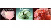
The scanning electron micrographs of phosphate-permanganate, GBA and dichromate coatings showed networks of gel like structure distributed all over the surface, which, after drying, hardened to give microcracked pattern.
The surfaces of the MAO and MAFA coatings exhibited porous morphology with pores distribution all over the coating. SEM observations revealed that the MAO silicate-coated surface had pores of 2.76±1.41µm size, which were irregular, and they are of different sizes. However, the phosphate-based coating mainly had large size circular pores (7.31±3.41 µm diameter). The formation of the MAO coating is based on the sparks passing through the oxide layer and generating the electrical discharge tunnels. MAFA coating clearly showed an irregular porous layer with pores diameters in the range 0.5–5 µm covering the surface.
The elemental composition (wt%) of various chemical conversion coatings studied on magnesium alloy AZ31B by EDX analysis are presented in Table 3.
|
Coating/ |
Phosphate- |
GBA | Dichromate |
MAO- |
MAO- |
MAFA |
| O | 38.00 | 43.07 | 48.30 | 54.19 | 53.68 | 45.96 |
| F | 2.59 | 3.09 | 4.34 | 10.21 | ||
| Na | 0.51 | 2.49 | 4.35 | 3.95 | ||
| Mg | 48.07 | 23.12 | 13.34 | 24.70 | 22.77 | 13.17 |
| Al | 1.70 | 4.21 | 1.22 | 0.81 | 0.48 | |
| Ca | 0.92 | |||||
| Cr | 12.21 | 33.12 | 10.61 | |||
| Si | 14.72 | 1.09 | ||||
| P | 7.08 | 14.38 | 15.01 | |||
| K | 1.74 | |||||
| Zn | 1.29 | |||||
| Mn | 2.12 |
The impedance spectra of the coatings in 5 wt % NaCl solution was recorded as Nyquist and Bode plots. The Nyquist plot showed a single semicircle for all the samples. At the high frequencies, the interception of the real axis in the Nyquist plot is attributed to the solution resistance (Rs), and at the lower frequencies, the interception with the real axis is ascribed to the charge transfer resistance (Rct). Since the diameter of the capacitive semicircle represents the resistance of the coatings, it can be said that the resistance decreases significantly with the decrease in diameter. Higher Rct values represent better corrosion resistance [161]. The MAFA coating exhibited higher Rct values than the other coatings. From this plot, the protective nature of the coatings was found in the following order: modified acid fluoride > MAO phosphate > MAO silicate > dichromate > GBA > phosphate-permanganate > bare magnesium.
The impedance and phase angle maximum in the high frequency region decreases in the order of MAFA > MAO phosphate > MAO silicate > dichromate > GBA > phosphate-permanganate coating. This indicates a decreasing order of the protective properties of the coating. The poor corrosion resistance of phosphate-permanganate, GBA and dichromate coatings can be attributed to electrolyte penetration through cracks and reacting with the underlying magnesium substrate leading to the formation of magnesium hydroxide corrosion products which destabilize the coating by increasing its porosity [73]. MAFA exhibits a higher impedance value compared to other coatings. This may be attributed to the presence of a higher percentage of fluoride (10.21 wt %) in the form of MgF2 in the coating. All other coatings contain only 2–4 wt % of fluoride. The presence of fluoride element increases the anti-corrosion stability of the anodized layer because of incorporation of the insoluble MgF2 in the anodic matrix [162]. The impedance data of different conversion coatings on AZ31B alloy in 5 % NaCl solution are shown in Table 4.
| Conversion coating |
Rs (Ωcm2) |
Rct (Ωcm2) |
| Bare Mg | 5.8364 | 27 |
| Phosphate-permanganate | 19.639 | 2,561 |
| GBA | 40.313 | 4,480 |
| Dichromate | 15.851 | 4,845 |
| MAO-silicate | 29.086 | 87,015 |
| MAO-phosphate | 18.926 | 88,088 |
| MAFA | 288.75 | 242,100 |
The electrochemical linear polarization data, corrosion potential (Ecorr), corrosion current density (Icorr), and polarization resistance (Rp) deduced from the Tafel plot also showed that the MAFA offered higher corrosion resistance than other coatings. The linear polarization results were more or less in accordance with the electrochemical impedance data. From these studies, the corrosion resistance of the coatings was found to be in the following order: MAFA > MAO phosphate > MAO silicate > Dichromate > GBA > Phosphate–permanganate > bare magnesium.
6 Conclusions
Because of their high strength-to-weight ratio and relatively high stiffness, magnesium and its alloys promise great potential as lightweight structural materials for various applications. However, their widespread applications are limited due to their poor corrosion resistance and surface mechanical properties. The present increased confidence of magnesium alloys can largely be traced to the development of more corrosion resistant alloys as well as improved methods of surface protection. In last few decades considerable advances have been reported in the area of chemical immersion and anodizing processes for protection of magnesium alloys. However, still a tremendous scope of research and development exists in this area to provide impetus for the commercial exploitation of this dream material. Though the efforts have been continuing from a long time, but there exists a need for focused accelerated efforts in the development of advanced magnesium alloys with superior mechanical and corrosion resistance properties. Also, there is necessity of detailed studies in surface engineering to establish the robust coating processes that can ensure adequate surface protection along with requisite functional requirements towards various applications of magnesium alloys.
In this article the chemical conversion coating processes available for magnesium alloys are briefly depicted for ready reference of users. Comparative studies on the corrosion behaviour of some of the important chemical conversion coatings on magnesium alloys have also been outlined to enable the user to choose the correct coating for specific functional requirement. In general, the chemical immersion processes provide poor corrosion and abrasion resistance than the electrolytic processes. Micro arc oxidation and modified acid fluoride anodizing processes offer far superior corrosion resistance for long term application. Of late, there has been increasing interest in the development of micro arc oxidation coatings with many additives to improve the surface mechanical properties. The hybrid composite and nanocomposite coatings in addition to superior corrosion protection deliver other requisite functional properties, viz, hydrophobicity, thermo-optical, nanomechanical properties.
Acknowledgement:
The author thankfully acknowledges the support of his former colleagues, A. Rajendra, R. Uma Rani, N. Sridhara, Anju M. Pillai, T. Harikrishna and Arjun Dey, of U. R. Rao Satellite centre, Indian Space Research Organization, Bangalore, India
References
[161] C.N. Cao: Principle of corrosion electrochemistry, Chemistry Industry Press, Beijing, (2004)
[162] S.V. Lamaka; G. Knornschild; D.V. Snihirova; M.G. Taryba; M.L. Zheludkevich; M.G.S. Ferreira: Electrochim. Acta, 55(2009) 131–141