Whether the phrase 'burning on the nails' originates from the monastic world or from the torture chamber will probably never be clarified. Legends and fairy tales are also used to explain its origins. In any case, it must have been unpleasant if you were too eager to pray or inattentive. It also gets hot in the reflow oven: the temperatures have to be brought above the melting point of the alloy to create wetting and a solder joint. On the other hand, you have to be careful that it doesn't get too hot, because then components and circuit boards suffer.
The question of how to control this has often been on the minds of solderers and equipment manufacturers. Not all engineers are able to design a multi-stage convection system in such a way that the various modules actually maintain the set temperatures over longer production times without smearing them across different zones.
Fortunately, someone has discovered temperatures and invented scales for them. So we measure in Celsius [2] or Fahrenheit [3] or, scientifically, in Kelvin [4]. However, in an oven like this, you don't work with the traditional mercury thermometer, of course, but with more modern means.
Before starting such work, however, a few details need to be clarified. First and foremost is the question of what you want to achieve. To do this, you need to study the assembly well and research the key data for thermally sensitive components and for the circuit board. This relates to the temperature and the respective dwell time. The paste, which consists of a metal alloy and the flux, has a significant influence on a desirable temperature curve, whereby flux refers to a considerable number of chemicals.
As with components, the flux also has certain thermal specifications, i.e. temperatures and dwell times at which it reacts and others at which it fails. One is desired, the other feared - and everything is much more critical since lead-free technology.
Armed with this knowledge, the soldering expert now draws a nice curve, which is ideally followed by the assembly in the oven.
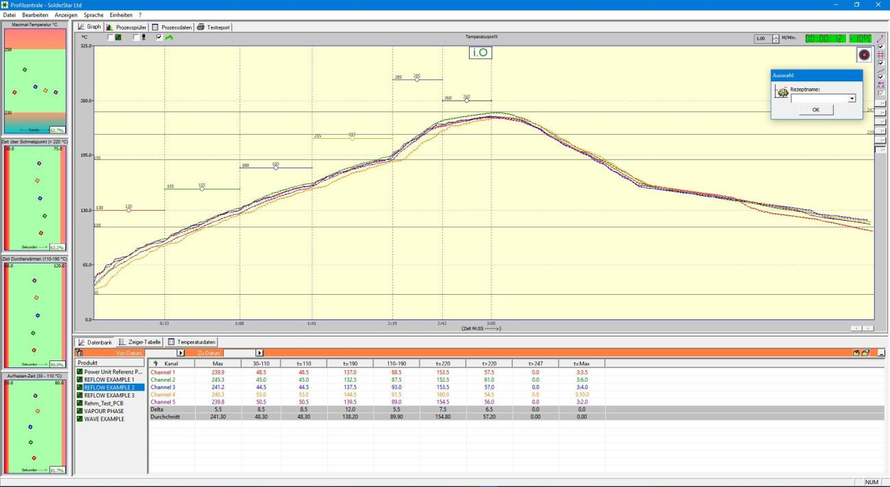 Thermal profile; image: PhoenixTM/SolderstarWhethera profile can be run for more than one assembly needs to be investigated. However, since the 'lead-free' requirement came into force, such 'families' have become smaller and smaller, so that mixing different products on one line is associated with difficulties and/or delays.
Of course, it would be great if the ideal curve could be achieved straight away, as the differences in mass alone, which are normally evident on the assembly, stand in the way of this. It is also clear that there is a heating dependency between the irradiated or heated surface and the internal volume. This is why assemblies heat up faster at the edges than in the middle, which also applies to components.
The profiles are measured when the machine is created and set up, but must then be monitored regularly. Such monitoring is important because products soldered with profiles that have gone out of control represent a real product risk. How often this has to be done has to do with costs, among other things, because every time a profile is measured, no product runs through the system. In addition to labor costs, there are also production losses, which can be considerable. This is offset by the risk of defective products.
If we assume that in mass production, an hour costs €15,000 (in Shenzhen, some companies 'drop' a finished laptop computer worth more than €1,000 from the production line every 15 seconds), then the company loses €250 per minute if no device is produced.
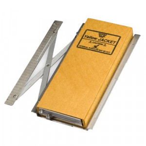
You can measure with tachographs, but the market offers quite a selection of devices that can save a lot of work.
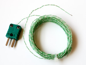
These work with different or specific thermocouples that are supplied with the device or can be purchased elsewhere. With some skill, you can also save money here by buying a roll of these wires and making the elements yourself. It is important to note that there are a number of different wire compositions that are used for different temperature ranges. They also come in different wire thicknesses. Thinner wires have faster reaction times and are easier to attach to an assembly, but are less tensile. You can quickly learn how to do this correctly from the Internet - but then don't forget to calibrate.
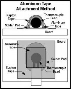
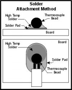
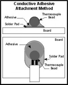
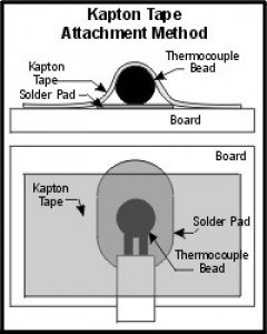
The thermocouples must now be attached to the module. There are a number of options for this, but they differ in terms of reliability and range from soldering to different bonding methods.
The first thing to consider is whether to make a 'golden assembly', which can be used several times but will probably be scrap after a few runs, or to make a new assembly each time.
Most devices have connections for several thermocouples - and now you have to scratch your old head and think about where best to place them on the assembly. Basically, you try to guess where the hottest spot might be and where the coolest spot might be, the one that takes the longest to heat up. Then it's probably the turn of the sensitive components.
Of course, there are also more scientific methods of finding these points, such as thermography or infrared photography.
Do you only measure on the top of the component or also underneath, because with large body surfaces you should know whether the beads underneath reach the required temperature?
X-ray systems help to ensure that the thermocouples have landed where you want them to. In some cases, you will even drill through the circuit board to place the sensor exactly where you want it.
There are a number of tricks you can use to make your life easier, such as routing the wires. All this is explained in free seminars offered by device manufacturers, which are also available in the electronic media.
About the person
Prof. Rahn is a globally active consultant in the field of joining technology. His book on 'Special Reflow Processes' was published by Leuze Verlag. He can be contacted at
References
[1] 1539 - Eberhard Tappe humanist and collector of proverbs
[2] Anders Celsius (1701-1744) Astronomer, physicist and mathematician
[3] Daniel Gabriel Fahrenheit (1686-1736) physicist, inventor and instrument maker
[4] William Thomson, 1st Baron Kelvin (1824-1907) Mathematician, mathematical physicist and engineer
Literature
Easy-to-follow instructions for handling of thermal profiling instruments, www.ecd.com
Ed Briggs; Ronald C. Lasky: Best Practices Reflow Profling for Lead-Free SMT Assembly, SMTA China (Shanghai) 2009
NingCheng Lee: Reflow Soldering Processes and Troubleshooting SMT, BGA, CSP, and Flip Chip Technologies, Newnes Publishing
Tips on att. thermocouples; Malcom Co., Ltd.
Cameron Sinohui (KIC), A Comparison of Methods for Attaching Thermocouples to Printed Circuit Boards for Thermal Profiling, Feb. 23, 1999, Conference Paper presented at Nepcon West 1999, Session TS-19
Image sources
K. I.K. Thermal: www.kicthermal.com
Electronic Controls Design Inc.: www.ecd.com
PhoenixTM/Solderstar: www.solderstar.com


