Miniaturization and the increasing complexity of assemblies make the selection of suitable test procedures increasingly important. A combination of different test procedures - for example JTAG/Boundary Scan and In-Circuit Test - is ideal for optimum test coverage. This also applies to assemblies where the test resources of the ICT test system are insufficient or where the test points are no longer available due to miniaturization. The authors use a practical example to illustrate the possibilities and advantages.
A.T.i. Software has been using the boundary scan equipment from Göpel electronic for many years and with great success. The possibility of interference-free signal transmission (differential) is ideal for the production environment. The ICT tester shows its strengths in analog testing. At the digital level, on the other hand, the full benefits of boundary scan technology can be exploited. This also makes it possible to test digital components where no physical test points are available. This applies to DDR RAM, for example, as EMC specifications or routing on inner layers often prohibit test points.
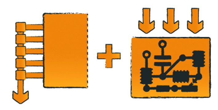
 Fig. 1: Combination of BST and ICT
If the boundary scan equipment and the ICT tester are combined, in this example with a Teradyne LH121LX test system, components can be digitally stimulated via boundary scan and analog measurements can be carried out by the ICT system. This makes it possible to test AD/DA converters, for example, which is not possible with pure boundary scan technology or pure ICT systems without additional hardware.
Programming in the production environment
The in-system or on-board programming of electronics is an important part of production testing today. Göpel electronic provides a large component library for the various programming algorithms of the components. Programming is not limited to the JTAG port. Support for the SWD or the Spy-By-Wire protocol is also offered. This allows testing and programming to be completed in a single step, especially with small amounts of data. If the ICT adapter is designed accordingly, the various emulation technologies from Göpel can also be used to increase test coverage or reduce test and programming time. With VarioTAP, for example, processor functions can be used without having to rely on programming them(Fig. 2).
Application example: Vacuum adapter for the Teradyne ICT tester
In this adapter, an assembly with 3200 circuit nodes but only 1500 test channels was realized. In total, approx. 3400 assembled components had to be tested, of which approx. 3100 were analog and approx. 300 hybrid or digital components. The digital components also included two CPLDs and two processors. Some of the analog components were tested by the tester in a cluster test. The hybrid and digital components are tested by the Göpel electronic hardware with the support of the in-circuit tester.
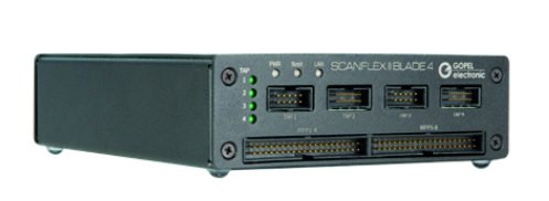
The new boundary scan controller Scanflex II Blade 4 with two SFX II TEM and TIC Type 02/SR is used and connected to the adapter via a cable connection. Göpel also offers plug-in cards for many test systems, eliminating the need to connect external cables(Fig. 3).
 Fig. 3: Scanflex II blade controller
The basis of every boundary scan test sequence is the so-called infrastructure and interconnection tests. In the infrastructure test, the integrity of the boundary scan chain is checked first. The boundary scan ID of the blocks is also read out. This makes it possible to check whether the correct components are fitted. The interconnection test checks the connections between the Boundary Scan-capable devices. It also tests the functionality of pull-up and pull-down resistors. This makes it possible to quickly and reliably determine whether there are soldering and assembly faults (short circuit, stuck-at or soldering faults on resistors) on the circuit board. Further boundary scan test steps check individual ICs or entire clusters at functional level. The processors and CPLDs mentioned above are also programmed in the process. VarioTAP technology is used for the two assembled processors on the module. This allows programming to be carried out quickly and reliably during the production test sequence.
VarioTAP also makes it possible to carry out a functional test of the DDR RAM module in real time or to access internal processor registers. This allows the RAM to be tested by the processor under real operating conditions. Access to the internal registers also makes it possible to access and test the internal AD converters of the processors. Most components do not have boundary scan-capable cells at these inputs; therefore these pins cannot be tested with the classic boundary scan.
The CPLDs can be programmed using a standard SVF file. If only the data set of the CPLD is available, it must be converted using the program released by the manufacturer. These are usually freely available and integrated in most development environments. The Göpel electronic software system Cascon natively supports programming using SVF. Various digital components are also tested. The large library can be used for this. This means that I²C components, parallel ADC and DAC converters and various other types can be tested. In the case of the AD and DA converters on the module, several are also connected in parallel to a data bus. The ICT tester is used to apply suitable test voltages to all AD converters and evaluate them using the System Cascon software. The procedure is reversed for the DA converters.
The DUT also has a wide range of digital inputs and outputs. Like the DA and AD converters, these are connected to a bus system. In addition, the inputs and outputs are electrically isolated from the connectors by optocouplers. The 12V signals are applied or measured with the ICT tester and the levels on the processor are checked or stimulated with the boundary scan test. This makes it possible to test the circuit fully automatically under real conditions in a short space of time. Driver components, usually high-side and low-side drivers, are also part of the test specimen. Switchable loads allow the various switching states and overcurrent conditions to be tested in accordance with the application.
Conclusion
The above examples of a real DUT test sequence show the advantages of combining ICT and BS technologies. Ultimately, it depends on the specific board to select the optimum test strategy for a product and to develop the corresponding test steps. In the example shown, a very good result was achieved: The test coverage of the physically testable components is almost 100%.


