Novel EMC coating systems using multilayer concepts for improved future shielding effectiveness in the frequency range from 2 MHz to 1.4 GHz - simulation and measurement
1. introduction
All technical metal housings, cable shields, connector housings and metal sheets that use conventional metallic copper coatings have a major disadvantage. Although there is good basic shielding attenuation of the end structures in practice, this does not exist over the entire frequency range. According to Schwab/Kürner, in the range of resonance frequencies of practical geometries, even with EMC conductive coatings, we have to deal with 'resonance catastrophes' [1], in which the shielding attenuation collapses significantly. All current EMC coatings applied to practical structures exhibit this effect. This problem is explained below using a metal enclosure with a metallic outer coating.![Abb. 1: Schirmdämpfung S eines Gehäuses in dB in Abhängigkeit der Frequenz, höchste Schirmung bei – 80 dB, geringste Schirmdämpfung bei 0 dB [4]](/images/stories/Abo-2024-05/plus-2024-05-028.jpg) Fig. 1: Shielding attenuation S of an enclosure in dB as a function of frequency, highest shielding at - 80 dB, lowest shielding attenuation at 0 dB [4]
Fig. 1: Shielding attenuation S of an enclosure in dB as a function of frequency, highest shielding at - 80 dB, lowest shielding attenuation at 0 dB [4]
The theoretical resonances of a metal enclosure are shown in Table 1.
|
No. |
Resonant frequencies per waveguide mode |
Exact resonant frequency |
|
1 |
f 101 |
330.6 MHz |
|
2 |
f 201 |
463.3 MHz |
|
3 |
f 301 |
624.6 MHz |
|
4 |
f 110 |
203.2 MHz |
|
5 |
f 102 |
576.3 MHz |
|
6 |
f 011 |
283.6 MHz |
|
7 |
f 111 |
339.9 MHz |
|
8 |
f 010 |
78.8 MHz |
With these real 'resonance disasters', the shielding attenuation drops to 5 dB at around 250 MHz. This effect of decreasing shielding attenuation and resonance minima is a disadvantage of all metal enclosures and this corresponds approximately to a Cu-coated enclosure from all suppliers. This means that all conductive practical lacquer structures have the disadvantage of a drop in shielding attenuation.
This problem is to be remedied. In the task to be solved of improving the shielding attenuation of conductive lacquer structures, such as a metal housing, the following hypothesis is put forward:
By using a new multilayer lacquer shielding variant with a simple product extension, the shielding attenuation values of these new technical structures (housings, cables, connectors, partial sheets) of the future can be significantly improved.
In the following, a solution using a new type of EMC coating system is proposed to the user from a theoretical and practical point of view.
2 Theoretical simulation
The technical problem discussed in Chapter 1 was solved theoretically by means of an analytical simulation.
The following initial values were selected for the simulation of the paint multilayers(Table 2):
|
Layer thickness [mm] t |
Conductivity [S/m] σ |
Permeability [H/m] μ |
|||
|
First absorber |
4 |
10-5 |
7500 |
Two multilayer (2) |
Four multilayer (4) |
|
First conductive polymer |
3 |
50000 |
10-4 |
||
|
Second absorber |
3 |
10-5 |
7500 |
||
|
Second conductive polymer |
4 |
60000 |
10-4 |
 Fig. 2: Shielding attenuation of the two multilayers as a function of the layer thickness at a frequency of 200 MHz
The following applies to the calculation of the shielding attenuation S [0].
![]()
T is the total transmission coefficient and is calculated using :
tn is the thickness of the respective layer and P can be determined as follows:
ηn is the respective internal impedance of the layer. To determine this, it is important to know what type of layer it is.
The following applies to an absorber varnish
and for a conductive coating polymer:
σn is the electrical conductivity, which can be found in the previous Table 2. The permeability μn [2] of all layers can also be found in Table 2. The frequency f was chosen to be 2 MHz. The symbol γn already appears in formula (2) as well as in formula (4a). This stands for the propagation constant of the respective layer and can be calculated as follows:
The last missing value is the reflection coefficient q. Its formula is as follows:
The tool is intended to be used to make predictions for the behavior and indications of the multilayer, which are then validated by subsequent measurements.
According to the simulation results, changing the parameters of the paint absorber layers only has a minor effect on the amount of shielding attenuation. This should be done primarily with the varnish polymer layers. Here, increasing the layer thickness shows a greater improvement in the shielding effectiveness than with the conductivity.
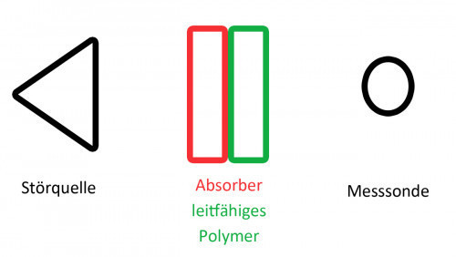
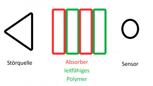
In the case of a two-layer multilayer, the absorber layer should come first, starting from the interference source, followed by the lacquer layer of the conductive polymer (see Fig. 3). Based on this, the arrangement in Figure 4 results for the four-layer multilayer.
However, the effect of the absorbers on the resonance compensation cannot be considered in the simulation. This must be done in practical tests. The absorber effect also plays a role here. The greater this is, the higher the compensation of the resonances should be. The simulation results also show that the shielding attenuation effect increases in proportion to the frequency of the external electromagnetic field.
3 First experimental tests with a new type of EMC multilayer coating
In an initial experimental test, IMG developed its own varnish multilayer system (according to the specifications of the theoretical simulation). This coating system suggests a positive practical effect. A metal connector was used as the basic application. The multilayer coating was applied to this using the simplest of techniques. The aim of the experiments is to compare the interference emission of the old connector to the new connector with the new EMC multilayer coating system. The interference emission measurements were carried out in accordance with standard VG 95373/T15 in the frequency range 1100 MHz - 1400 MHz in the electromagnetic anechoic chamber. Figure 5 shows the emission curve of the field strength of the bare connector without lacquer coating, the antenna without connector and the connector with the new EMC lacquer coating. As a result of the application of the new lacquer system, it can be seen that the emitted electric field strength of the transmitting antenna (blue curve) can be seen. The effect of the connector with the transmitting antenna is shown in orange and the effect of the connector with the multilayer coating is shown in gray. The reduction in field strength by the connector and by the connector plus EMC coating multilayer is at least 5 dB. The positive effect of the new EMC coating has thus been proven experimentally.
 Fig. 5: Field strength emission at a connector with and without innovative lacquer shielding layers and at the transmitting antenna
4. summary
The summary presents design information on the layer configuration of the novel multilayer varnish for improved shielding attenuation.
Rules for the optimum layer configuration
- R1: The shielding effectiveness can be improved mainly by increasing the layer thickness of the conductive polymers.
- R2: Higher shielding effectiveness can be achieved by using a four-layer multilayer in the arrangement absorber - conductive polymer - absorber - conductive polymer.
- R3: An improvement of the two-multilayer compared to the four-multilayer can only be achieved by increasing the layer thicknesses.
- R4: The influence of the absorber material values should always be taken into account due to resonance compensation.
Limitation
All statements made in this report are the result of simulations. Their accuracy still needs to be verified by practical measurements. They are intended as a recommendation for the design of the two- and four-unit multilayers. The shielding effectiveness values in this report are purely theoretical. They can never be achieved in practice or a correction factor must be determined by practical tests. The values selected for the layer absorbers and conductive polymer are taken from the Internet and are intended to reflect reality to some extent. The user is recommended to provide the material values of the materials used by him in order to be able to make statements for these with the simulation program created. The simulation program cannot take into account the occurrence of possible resonances, as the simulation is a field-theoretical analysis of plane plate systems. These resonances should primarily be compensated for by the absorbers. The extent of this effect still has to be verified by practical measurements. Material properties such as microstructural properties are not taken into account in the program. It can therefore be stated at the end of the paper that IMG has developed a basic concept for a new multilayer concept for an EMC coating system, which it has also built itself. In the future, IMG will further optimize the novel EMC multilayer coating system with regard to a larger frequency range and an improved coating structure.
Literature
[0] Leute, U.: Plastics and EMC. Electromagnetic compatibility with conductive plastics. Contact & Stu Volume 678. Renningen: expert verlag (2016)
[1] Schwab; A., Kürner; W.: Electromagnetic compatibility, 6th edition, Springer/ VDI Verlag, (2011), ISBN 978-3-642-16610-5, p. 258.
[2] Aron Tesfalem Berhe, Frank Gräbner: Influences on shielding. hf-praxis (2020), 3, p.34-37.
[3] Bronstein, Semendiajew, Musiol, Mühlig: Taschenbuch der Mathematik, Verlag Europa-Lehrmittel, Haan-Gruiten, (2013)
[4] MATECH Final Report 'Passive Protection - New Materials New materials and technologies for effective passive electromagnetic protection to increase the reliability and environmental compatibility of electrotechnical/ electronic systems and visualization/ visualization of electromagnetic energies', BMBF project of IMG (2001), 1, FZ Jülich.


