Powder coatings are an attractive alternative to solvent-based coating systems, especially in times of increasingly strict VOC emission guidelines. For example, the revision of the BAT data sheet Surface treatment using organic solvents (STS) is associated with adapted binding emission standards. Despite being solvent-free, powder coating is by no means easier to handle than wet coating. Correct pre-treatment, compliance with painting parameters, appropriate storage of powder coatings and much more present challenges that can only be mastered with extensive specialist knowledge.
1.1 The first step towards adhesion: pre-treatment
Adhesion problems with coatings are among the most typical and serious types of damage that occur in industrial surface treatment. The reasons for this can often be found in a lack of understanding of the need for pre-treatment. A lack of technical understanding of the pre-treatment process is also often the cause of poor process quality. The following examples of damage show how errors in pre-treatment can affect the adhesive strength of the coating.
1.2 Chipped - correct pre-treatment of laser cut edges
The order from a regional court to DFO was clearly defined and seemingly easy to answer. The coating on powder-coated steel components had flaked off in the area of laser-cut edges (Fig. 1a). On the underside of the coating, a typical black scale layer was visually recognizable, as it occurs during laser cutting without shielding gas. This layer must be removed before the coating process, as it does not bond sufficiently to the steel. If this scale layer is overcoated, poor adhesive strength and corresponding delamination of the coating must be expected. Analytical tests ultimately confirmed this assumption by detecting the scale layer on the underside of the delaminated coating.
 Fig. 1a: Chipped powder coating
The coater's lawyer confirmed the presence of the scale layer in principle, but not that the coater could see it: "Scale and oxide layers are demonstrably transparent in their raw state and are not recognizable. The oxide coating described by the expert only becomes visible for the first time through discoloration [...] as a result of the coating process and the heating of the coating to 200 degrees for a period of 20 minutes."
The fact that the scale layer is indeed visually recognizable beforehand was demonstrated by means of two sample parts during the oral hearing. One of the comparison components had been cut with shielding gas (prevents the formation of oxidation products of the steel = scale layer) and the other without shielding gas. The black scale layer was clearly visible on the component cut without shielding gas. However, the comparison component was shiny metallic.
1.3 Blasting - but the right way!
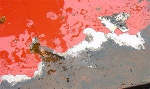 Fig. 1b: Metallic sheen due to protective "oil coating "In the second case study, the coating on steel machine components that had been blasted before painting came off over a large area.
Due to heavy contamination, the affected components were cleaned with a high-pressure cleaner before being inspected. This caused further parts of the coating to become detached. Shiny metallic areas (Fig. 1b) were visible under the flaking coating. The representative of the machine manufacturer explained that this was an indication of good cleaning.
The shiny areas were obviously well protected from corrosion by an oily coating, but naturally prevented sufficient adhesion of the coating.
When inspecting the pre-treatment and painting process, it quickly became clear where the comparatively high quantities of oil on the component surfaces were coming from: The individual components of the machine were exposed to cooling lubricants as part of the mechanical processing.
As the blasting medium did not contain an oil-adsorbing additive at the time, the cooling lubricants were distributed evenly over the component surface. The company now uses an appropriate additive and no further loss of adhesion has occurred since then.
2.1 Errors in powder coating production
The causes of coating defects can be very diverse and can sometimes only be identified by means of a lengthy search or not at all if there is a lack of knowledge about the general coating technology and individual processes. The causes can lie well before the coating process, so that measures relating to the coating periphery remain ineffective.
Narrowing down or eliminating possible causes is therefore an important tool for saving time and money in troubleshooting. Detective work, experience and logical thinking are the basic prerequisites for this. The following case studies illustrate how efficient such an approach can be, in which a narrowing down to the manufacturing process of the powder coating used led to a quick identification of the cause and ultimately to the fault solution.
Case study 1 - Cooker in the coating
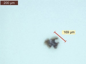 Fig. 2a: Defect inspection by light microscopy: brownish, translucent inclusions in the coating At a manufacturer of aluminum panels, localized defects were found on the entire component surface after powder coating. During initial discussions with the powder coating manufacturer, they described the defects mainly as "boilers" and "dirt inclusions".
"dirt inclusions". It was assumed that the application process must be the source of the defect. However, the defect pattern only occurred in one powder coating batch, which motivated the manufacturer of the panels to take an analytical look at the defect pattern. The light microscopic examination directly ruled out stoves as the cause of the defect, as brownish, translucent inclusions were visible in the coating in all defect areas (Fig. 2a).
An IR spectroscopy of the inclusions showed a mixed spectrum of powder coating (polyester-based) and polyvinyl chloride (PVC). An SEM image of one of the defects confirmed a marbling of the PVC particle with powder coating. It was therefore suspected that the PVC particles had got into the powder coating during production. One possible source of error was in the extrusion area: PVC is often fed through the extruder to clean extruders, as it is a low-cost plastic. If PVC residues remain in the extruder after cleaning, they are picked up and discharged by the subsequent paint batch. The subsequent grinding process crushes the PVC together with the remaining powder coating so that it is finely ground in the powder coating and is also filled.
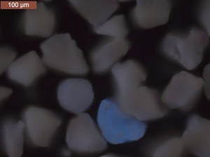
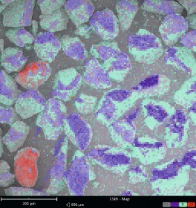
In order to prove that the faulty powder coating batch really contained PVC particles, the PVC particles, which visually corresponded to the powder coating particles in size and shape, first had to be localized and marked using fluorescence microscopy (Fig. 2b). Large amounts of chlorine were detected in the fluorescent particles by energy dispersive X-ray spectroscopy (EDX), which indicated the PVC particles in question (Fig. 2c).
The source of the defect pattern could therefore be clearly assigned to the powder coating manufacturing process. A search for the cause in the application process would therefore have been unsuccessful.
Case study 2 - Dirt inclusions in the coating
At a manufacturer of high-quality office furniture, coating inclusions could also be traced back to an error in powder coating production. Various powder coating batches were affected, but the problem did not occur in all colors. There were significantly more inclusions on black and red components, while white shades of the same powder coating base remained almost free of defects. The initial assumption that these were dirt inclusions due to inadequate cleanliness of the painting system was therefore very unlikely, as otherwise all colors would have been affected equally.
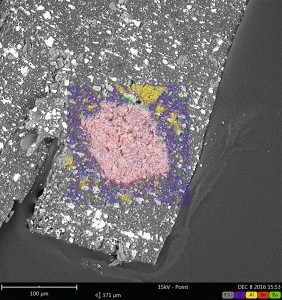
The defects could be cut open using a scalpel and the exposed defect area examined. Light microscopy revealed white, crystalline-looking particles on the one hand and transparent particles on the other. An examination by EDX showed large amounts of tin in the crystalline areas (Fig. 2d).
Tin can be used in organotin compounds as a reaction accelerator in polyurethane powder coatings. This additive is added to the powder coating in the form of additive granules (masterbatch) before extrusion.
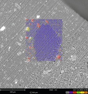
In the transparent areas, however, it was noticeable that neither inorganic fillers nor pigments could be detected, although they were present in the OK range (Fig. 2e).
The transparent inclusions exhibited almost the same spectrum in IR spectroscopy as the powder coating itself. Since IR spectroscopy is only used to characterize the organic structure of a coating, it can be concluded that these are unpigmented film-forming particles of the powder coating. Here too, therefore, it was not a question of foreign inclusions, but of insufficiently extruded and ground powder coating batches. The question of why white shades were not affected was easy to answer: While black shades achieve sufficient hiding power with a relatively small amount of pigment, white shades in particular, which are usually tinted with titanium dioxide, require a much higher pigment content. The reason for this is the poor hiding power of the pigment. However, a relatively high pigment content ultimately results in higher shear forces during extrusion, which improves homogenization in the extruder.
In this case too, the source of the defect was in the powder coating production process. Without an analytical view of the defect patterns, the logical linking of all facts relating to the defect pattern and cross-process expertise, the focus here would also initially have been incorrectly on the application process alone.
3.1 Process errors in powder coating
Time and again, errors occur in the powder coating process that cannot be assigned at first: The powder guns do not feed properly even though they are regularly serviced, clouds of powder escape from the storage container, the powder coating can no longer be fed properly, etc. Such faults can often be traced back to a change in the powder coating properties due to powder recovery, for example. One way of measuring the powder coating properties is to measure the flowability and fluidizability of the powder coatings. In the case of powder coating systems that are charged with the aid of tribo guns, a test method for measuring the tribological properties of powder coatings is also used.
The DIN EN ISO 8130-1 to 8130-14 series of standards for testing the properties of powder coatings is currently being revised. However, defects that are initially attributed to the powder coating can often be attributed to defects in the coating process. The most typical and most frequent process-related defects are described below.
3.2 The powder coating: correct storage
The following can be read on every powder container: "Store in a cool and dry place!". Anyone who has ever been annoyed by flour that has become damp can easily understand the second part of this recommendation. However, an analogy to baking can also be drawn with regard to cool storage: As soon as a cake batter is placed in the oven, various reactions begin that turn the batter components, which were previously only held together by moisture, into a chemically cross-linked mass. In the case of powder coatings, this corresponds to chemical curing in a powder oven. However, chemical cross-linking begins at significantly lower temperatures than the recommended curing temperatures, albeit much more slowly. The result is ultimately a lumpy powder coating that can no longer be processed.
As a rule, cool storage means a temperature below 25 °C. Many coaters want to store the powder coating properly and determine the driest place in the paint shop to be right next to the curing oven. However, temperatures here are usually well above 25 °C. If a powder coating stored in this way is mixed with fresh powder coating, in the best case only a poor flow is achieved. However, it can also happen that the coating becomes matt or even loses its adhesion. Powder coatings should therefore always be stored in air-conditioned storage rooms.
3.3 The powder coating process
A powder coating system has an application efficiency of 98 % - at least that is the widespread assumption. Theoretically, these values can easily be achieved, but in practice they are usually significantly lower. If, for example, a cyclone is used for powder recovery, the application efficiency is reduced to a maximum of approx. 92 %. Despite this very high deposition efficiency compared to coating with liquid paints, often only the overall efficiency, i.e. the deposition efficiency when recovering the powder coating, is considered.
However, the initial application efficiency is of greater importance. This refers to the quantity of powder coating that is deposited on the workpiece during initial application. In practice, this first application efficiency is often only 20-30% due to excessively large powder coating clouds, for example. This means that the majority of the powder coating has to be recovered.
The negative consequence of this practice is a shift in the particle size distribution. During powder application, the powder coating particles separate differently depending on their particle size. This results in a shift in the particle size distribution in the recovered powder coating towards smaller powder coating particles. This recovered powder coating therefore has different properties than a powder coating without recovery. This can result in coating problems or, in the worst case, the powder coating becoming unprocessable.
This segregation has a particularly critical effect on dry-blend metallic powder coatings. This can lead to major color shifts, as the metallic pigments are not bonded to the powder coating particles.
The theoretical application efficiencies can be achieved with as little effort as possible while maintaining high coating quality:
- Minimizing the size of the powder cloud - i.e. the powder cloud should be adapted to the size of the workpiece. In practice, however, the largest possible powder cloud is often set so that as much powder coating as possible is deposited when the workpiece passes through this powder cloud.
- The number and arrangement of atomizers is optimized - i.e. more atomizers, each with a small application rate, which are adapted to the workpiece geometry, are more efficient than a few atomizers with a large application rate, where a lot of powder passes by the workpiece.
- The powder atomizers should only be switched on when workpieces are in position for painting. This should be self-evident, but in practice you still come across powder spray guns with permanent coating. The argument is often that powder recovery is loss-free.
3.4 The powder coating booth
Powder coating booths with powder recovery often do not have their own air supply, i.e. the booths draw in the air and thus also contaminants from the booth environment. Although the powder recovery systems are equipped with sieving devices, these sieves have mesh sizes of at least 100 µm so that sieving is possible at all. Contaminants smaller than 100 µm can therefore pass through the sieve. With typical coating thicknesses of 80 µm, such contaminants are therefore visible as inclusions in the coating. A separate air supply with controllable and constant air quality can therefore drastically reduce foreign inclusions.
4.1 The correct curing of powder coatings
As a rule, powder coating systems stand for robust and solid coatings. However, two things in particular must be taken into account when curing the powder coating: Firstly, the correct temperature and secondly, the correct curing time. If one of these factors is not optimally designed for the respective coating system, this can lead to serious defects. The case of damage described below is intended to underline the importance of adhering to these parameters.
In a paint store, metal pipes were powder-coated and then mechanically processed. It was noticed that the coating delaminated on exactly 50% of the pipes during this process. There are usually two most likely causes for such defects: inadequate pre-treatment or insufficient curing of the powder coating. In this case, a solvent test very quickly revealed that the powder coating had not cured properly. To do this, the surface of the coating was rubbed with a cloth soaked in solvent. The coating was found to be dissolving and the powder coating was clearly matt. In such a solvent test, a solvent should be used to which the sufficiently cross-linked powder coating is resistant (e.g. isopropanol). Consequently, the coating should not be soluble or matted in the wiping area. In addition, the degree of cross-linking can be determined for a more precise analysis using differential scanning calorimetry (DSC). This is recommended, for example, for powder coating systems that are not solvent-resistant even when fully cured.
There were now two possible causes for the coating delamination on the metal pipes. Either the temperature in the curing oven was not reached or the object temperature was not maintained long enough. To check this, a furnace curve was recorded using a furnace measuring device. It is important to ensure that the measuring sensors are positioned so that all areas of the product carrier can be adequately measured (e.g. top, middle and bottom). Different material thicknesses of the component to be coated must also be taken into account and measured individually. Furthermore, an oven curve should not be recorded in a relatively empty oven, as the heating rates can be falsified due to the mass in the oven, which would otherwise deviate from normal operation.
In this case, it turned out that the oven was too cold in the lower section. The reason was carelessness after cleaning the oven. During cleaning, the ventilation flaps were adjusted and as a result, there was a drop in temperature in this area. This was also the reason for the 50 % failure parts, as the pipes were hanging in two rows on top of each other.
5.1 Test methods - first understand, then test!
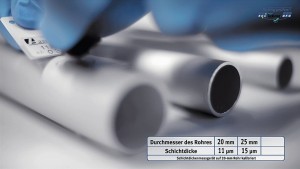 Fig. 5a: Deviations in the measured coating thicknesses when changing the radius of aluminum tubes without intermediate zeroingBusinessesand companies must regularly check the surface quality of their products. For this purpose, test methods are used for both the coating materials and the coatings, such as the cross-cut test, the flow time, the coating thickness measurement or the gloss level measurement. However, these test methods, which are supposedly quick and easy to carry out, carry the risk that the user may make mistakes when performing them. The regular and routine performance of such test methods is no guarantee of correct application. A lack of knowledge about how test devices work and about the physical and chemical processes that take place during the measurement often leads to supposedly inexplicable fluctuations in the measurement results or simply to incorrect measurements.
The simplest example of this is the coating thickness measurement of non-conductive coatings on metallic substrates using the magnetic induction or eddy current method: Here, for example, the effects on the measurement result can be serious if the measuring device was not adequately zeroed before the measurement.
Zeroing the coating thickness gauge on an uncoated substrate serves to provide the gauge with an initial value (zero value). Unfortunately, there is a widespread misunderstanding that calibration and zeroing of a coating thickness gauge are the same thing. For example, it often happens that the calibration plate supplied by the device manufacturer is incorrectly used for zeroing, which leads to incorrect measurements. The reason for this is that a substrate or component is required for zeroing that has the same material composition, material thickness, roughness and component geometry as the substrate on which the coating thickness is subsequently to be measured. All these properties influence the measured zero value, which results in a correspondingly falsified measurement result when zeroing on a different substrate. Deviations in the two-digit micrometer range can easily occur here. In various companies and businesses, it has been established during DFO Service GmbH company training courses, in which the topic of coating thickness measurement was also discussed, that very few users carry out zeroing at all before the measurement. In order to understand why zeroing is so essential for a sufficiently accurate measured value, it is therefore essential to familiarize yourself with how the measuring device works.
Another test method with an underestimated susceptibility to errors is the cross-cut test. According to DIN EN ISO 2409:2013, the cross-cut test is used to estimate the resistance of a coating to separation from the substrate when a continuous grid is cut into the coating up to the substrate. The degree of separation of the coating is the result of the cross-cut test.
However, cutting through the coating to the substrate is only approximately possible in practice and difficult to check.
For this reason, too deep a cut is often made to ensure that the coating has been severed in the cut groove. However, if the cut is too deep into the substrate, the substrate is partially displaced to such an extent that the coating flakes off, which would not have occurred if the test had been carried out correctly.
 Fig. 5b: Cross-cut using a multi-cutting device - tilting of the cutting edges and cutting grooves that are too deep lead to fraying of the substrate materialIn addition,DIN EN ISO 2409:2013 recommends the use of an adhesive tape to remove any coating particles that are still loosely adhering after the cross-cut test has been carried out, in addition to blowing and brushing the surface. This recommendation was often misinterpreted in the past and has evolved in many in-house standards to such an extent that certain fabric adhesive tapes with very high adhesive forces are used for a literal "adhesive tape tear-off". Such adhesive tapes can cause the intact coating to separate during removal and thus potentially falsify the result of the cross-cut. This adhesive tape tear is therefore basically another test that is not compatible with DIN EN ISO 2409:2013. It is no longer possible to compare different coatings that have been tested in this way.
The next example concerns the measurement of the flow time: To assess the viscosity of a coating system, the flow time is often measured in a flow cup, as this test method is quick and easy to use. There are usually two different flow cups in circulation: One is the flow cup according to DIN 53211 and the other is the flow cup according to DIN EN ISO 2431. The latter is characterized by an extended and therefore less turbulence-prone outlet nozzle and can therefore be seen as a further development in terms of measuring accuracy and repeatability of the flow cup according to DIN 532111. DIN 53211 was therefore withdrawn in 1996 and has therefore been invalid for over 20 years. Nevertheless, there are still far more run-out cups according to DIN 53211 in use today than run-out cups according to the valid DIN EN ISO 2431. In addition, most users are not aware of the physical limits and influencing factors (e.g. temperature, paint density, shear stress, etc.) that need to be taken into account when measuring the run-out time.
Only Newtonian liquids are suitable for measuring the flow time, as rheological effects of non-Newtonian liquids can lead to non-reproducible and misleading results.
However, for technological reasons, water-based paints usually have a pronounced structural viscosity and thixotropy. These are rheological properties that make the viscosity of the paint dependent on time and shear stress.
This makes the measurement of the flow time - regardless of the flow cup - an unsuitable test for water-based paints. In order to be able to make useful and comparable statements about the viscosity of water-based coatings in terms of application technology, the dynamic viscosity can be measured as a function of time at different shear rates, e.g. using a rotational viscometer.
For better process reliability, it is therefore worthwhile to understand how the test equipment works and to know the factors influencing the measurement results.


