Politically, resistance is described as a refusal to obey the authorities. Although it is carefully enshrined in the Basic Law, many politicians do not like it, as it undermines their power and reputation. It is therefore in the nature of things how resistance is seen and judged. Those who offer resistance in any form will see and evaluate it differently to those who are exposed to it. It is therefore usually a question of power as to who is the winner and loser. However, it is not unlikely that both sides will end up as losers. It is not for nothing that mathematical game theory shows that cooperation is 'better' than confrontation. Electrically, the whole story looks completely different ...
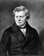
In electrics, the quotient of voltage to current defines the electrical resistance, a physical law that every high school student is probably familiar with under Ohm's [1] name. However, a slightly different relationship is of interest to soldering students, because if the current in the resistor (e.g. wire) causes a voltage drop, electrical energy is converted into thermal energy. The wire heats up or even gets hot - in the case of fuses, it eventually burns out. Where sufficient heat is generated, it may also be possible to solder, the engineers say to themselves, and they have already set their sights on resistance soldering.
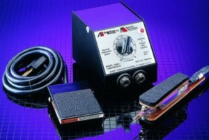
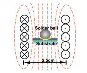 Fig. 5: Schematic diagram of reflow with alternating electromagnetic radiationAnelectric current is passed directly through the two metal parts to be connected. As the amount of current can be regulated, it is also possible to regulate the heat generated. Modern devices achieve sufficiently high temperatures to melt most solder alloys and make them flow. The overall quality and repeatability of these soldering processes has now been improved to such an extent that the solder joints are almost completely reproducible and at the same time the heat is localized in such a way that potential thermal damage to heat-sensitive components hardly ever occurs.
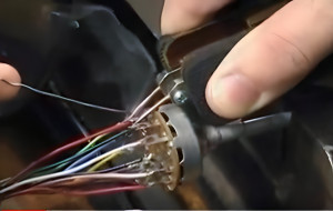
Solders in the form of paste or preforms are placed in the joint gaps first and as they almost always have the highest electrical resistance, they melt first making the heat easy to localize. Although occasionally some connectors or posts are soldered to assemblies with resistance, this technology is more suitable for cables, connections and similar geometric arrangements that are manufactured separately, i.e. far away from the sensitive assembly. Here, speed and quality are usually far superior to other processes such as flames or soldering irons.
In addition, the machine developers and suppliers have paid a great deal of attention to the safety of potential users, so that the commercially available devices can be handed over to workers largely without risk. However, since many hobbyists also use this technology - e.g. for electric toys and trains - and make their own devices, the possibility of electric shock must always be kept in mind.
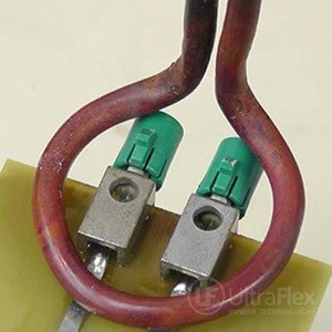
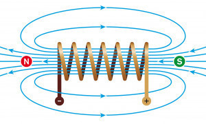
A related soldering method is induction soldering. It is related because the resistance in the soldered connection is also used here. In simple terms, the process can be explained by the fact that a magnetic field builds up around a conductor through which current flows (Ampère's law) [2]. If another conductor is moved through this magnetic field, eddy currents are created in it. However, you can also change the current so that magnetic fields constantly build up and collapse again. If the other conductor is then still in the constantly changing magnetic field, eddy currents are also generated in it. This is where the alternating current comes in handy, as it quickly changes its direction (polarity) and ensures that the surrounding magnetic field remains in motion. Correctly selected, the desired eddy currents are created and, in combination with the resistance in the metals and especially the solder, the heat required for melting is generated.
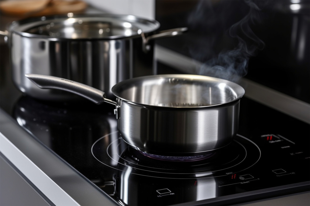 Fig. 6: Familiar from the kitchen - induction hotplates
In the application, the frequencies are roughly divided into medium frequency (1000-10,000 Hz) and high frequency (0.1-5 MHz), which are of course far removed from the 50 Hz that you get from a European socket. The lower the frequency, the deeper it penetrates into the metal. High frequencies mainly only heat the surface. As the heating process takes place directly in the workpiece, the energy density achieved with induction is remarkably high: 104 W/cm2. If you compare this with the widely used convection: 0.5 W/cm2 or radiation (electric muffle furnace): 8 W/cm2 or a soldering iron: 103 W/cm2, it is hardly surprising that the time required to create the solder joint is greatly reduced. Much of the success of induction soldering depends on the induction coil. The more precisely it is adapted to the problem at hand, the more likely the soldering will succeed without causing any other damage. To do this, you need to understand how the magnetic field is shaped around the coil so that you can direct it to where you want it to be.
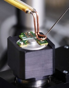
Induction coils are made from highly conductive copper wires, tubes or plates depending on the application, the selected frequency, the power density and the desired heating time. The induction coil is used to create a magnetic flux pattern so that eddy currents are generated in the workpiece and thus selectively heat the area of the assembly to be soldered.
The induction coil must be positioned precisely and reproducibly on the assembly so that the desired heating can be achieved. The air or coupling space between the workpiece and the inside of the coil should be minimized for efficiency reasons. Typical design gaps of 3.2 mm to 6.3 mm are appropriate for soldering with a spiral coil.
Although the vast majority of induction soldering has little or nothing to do with the assembly or electronics, there are still some examples, in addition to solar panels, that have successfully utilized the properties of induction soldering. One highly interesting new area of application is an innovative solder bumping process with local induction heating called ISHR (Induction Self Heat Reflow). This makes it possible to produce solder bumps for the eutectic SnPb, SnAg and SnAgCu solder balls on the Au/Ni/Cu pad without thermally stressing the components as with other methods.

To the person
Prof. Rahn is a globally active consultant in connection technology. His book on 'Special Reflow Processes' was published by Leuze Verlag. He can be contacted at
References
[1] Georg Simon Ohm (1789-1854) German physicist. He proved that in a current-carrying metallic conductor, the resulting electric current I corresponds to the quotient of the applied electric voltage U and the respective electric resistance R. This physical relationship is known as Ohm's law in his honor.
[2] André-Marie Ampère (1775-1836) French mathematician, physicist, chemist and philosopher.
Literature
D. Marvin: How Induction Soldering Improves the Process and Quality of Coax and Interconnect Assembly, iTherm Technologies, 2014.
H.A. Chan; M.A. Oien: Localized Soldering By Inductive Heating, U.S. Patent US 4,983,804, December 21, 1989.
V. Nemkov; V. Vologdin: Inductors with Magnetic Flux Controllers for New Induction Brazing Installations'; Centre for Induction Technology, USA.
An Rong et al: A New Solder Bumping Technology with Local Induction Heating, IEEE. 2005 6th International Conference on Electronic Packaging Technology.


