In Vietnam, the soup 'Pho' is eaten with chopsticks. One naturally wonders whether the Chinese-Vietnamese noodles can be 'broken in', as a good German would do, because the art of eating with chopsticks is not widespread in this country. In electronic production, it is less about chopsticks or spooning out and more about scooping. This is one of the problems with paste printing in the production line for surface-mounted PCBs.
According to various authors, paste printing (and pastes) is responsible for around 50-70% of all 'soldering defects' that are ultimately observed on such lines. The reason for this is actually easy to discover, because the many parameters involved in the printing process are almost frightening and few setters have mastered this variety. In addition to the very different pastes, you have to deal with the stencil and its production, the squeegee and the many possible settings on the machine itself.
Scooping is undesirable because it reduces the supply of solder on many critical surfaces. As pastes only consist of around 50 % metal by volume anyway - paste manufacturers like to state weight percentages that are actually irrelevant, but are an impressive 90 % - there is even less left for a durable soldering process.
Factors that influence scooping, i.e. the removal of paste from the inside of the surface, range from the squeegee to the direction in which the paste is spread over the stencil. Rubber or plastic squeegees are much softer than metal squeegees and are therefore easier to press into the openings. The result is a smear that is no longer truly horizontal. Sharp and thin edges are also less suitable than thick and rounded ones. But this is probably why the majority of companies have now turned to metal squeegees, which are much stiffer and more difficult to shape. Basically, this is a slight deformation of the squeegee in the area of the opening or occasionally a dragging along of adhering paste.
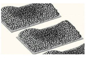
 Exhausted print images; Image: OptimaTechButeven among these metal doctor blades there are now so many variants - an Olympic competition, so to speak, of what can be patented - that they each have to be assessed separately.
A comparison is easier said than done, because even the IPC members have not yet presented a method that could make such a procedure halfway scientifically interpretable. All technical articles therefore deal with individual cases from which certain indications can be derived, but which do not provide an overall useful procedure.
So it's time to take a look at some of the factors that can have an influence on this state of emergency.
This starts with the design of the PCB, which determines how and where the components are mounted. Here it can already be ensured that the squeegee does not necessarily have to run over the greatest distance at the cut-outs during stencil printing. But what designer thinks about the production process?
The often propagated subdivision of larger cut-outs needs to be considered, as the additional bars require space and thus reduce the amount of paste applied. This may be more than is lost during scooping.
When buying a printer, you can put the Euros at the top of the list of criteria or make sure that the many possible parameters can be met as precisely as possible. In addition to the coating speed and the pressure on the squeegee, the coating direction should perhaps also be selectable.
A decision is required when printing: does the stencil lie directly on the PCB or do you choose a 'snap-off'? Snap-off is a holdover from the days of printing through screens and is used for two main reasons: to prevent the release of solder paste from the stencil apertures and to leave a thicker layer of paste on the substrate.
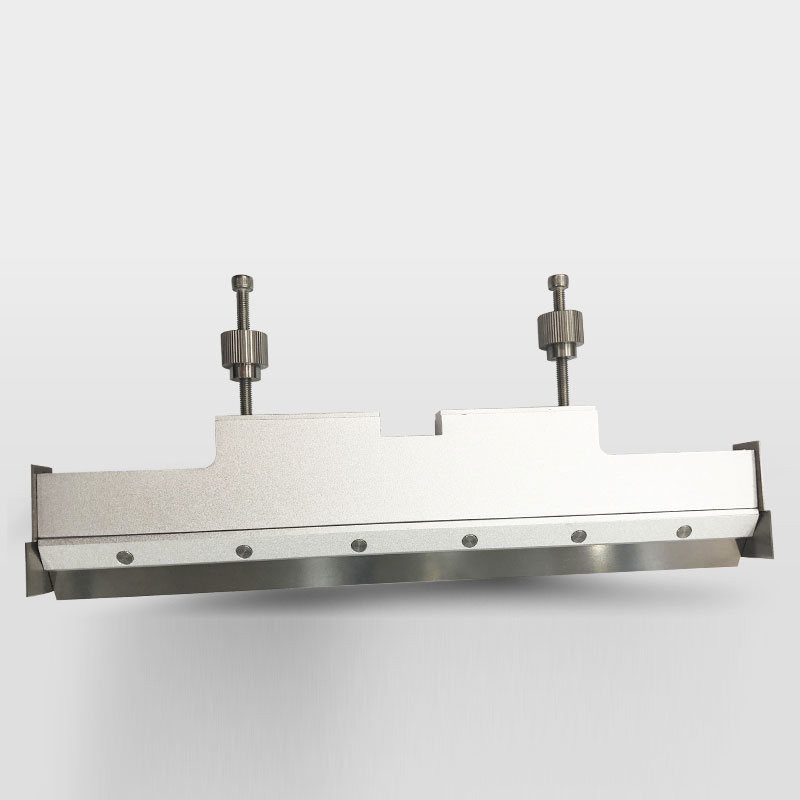
 Squeegee with metal blade (Yamaha squeegee); Image: YamahaHowever,'snap-off' is not a repeatable process and will not work in every case. It may still be permissible when using a poorly cut stencil, but this setting has significant disadvantages, especially with fine screens, because the sealing of the printable pad area by the stencil is completely lost.
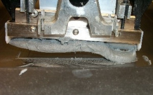
 Here it went wrong: Squeegee blade too long and badly adjusted; picture: IndiumSnap-offnaturally also has to do with the squeegee speed. This is usually selected differently, from approx. 1 cm to 30 cm per second, although even higher values are also possible. It is a known fact that the exhaustion occurs more often at low values than at high ones. Nevertheless, caution should be exercised, as a squeegee feed that is too fast regularly leads to poor prints, which results from the properties of the pastes. Pastes have rheological properties, which means that they become thinner under shear stress. This loss of viscosity is sometimes desirable, but if it is too high, it affects the print image.
The squeegee pressure, which is typically selected at around 450 to 600 g per 2 or 3 cm of blade length, also has an influence - and perhaps an even more critical one for this printing error - because during the cycle, an evenly distributed pressure must be exerted over the entire length of the squeegee blade so that all openings in the stencil are filled correctly, with the emphasis on 'correctly'.
Yes, and here a wide field opens up (following Petrowski [1] - but he formulated this for mathematicians) for the ladies and gentlemen at the printers, because the list of doctor blades is long and full of pitfalls. In addition, the choice depends on the paste, the stencil and, last but not least, the machine dictated by the management.
But let's give you a little help and a recipe that should be used with caution. With a 'correct squeegee pressure', you also achieve a more even paste height with application control. As a side effect, squeegee blade and stencil wear is reduced, which you should take into account in the long term!
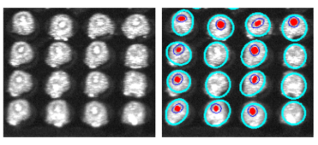
 Optical control indicates 'scooping' (Benedek)
Let's optimistically assume that your squeegee blades are correctly installed and adjusted and then you're ready to go:
- Select one of your flat PCBs
- Position it under the corresponding stencil
- First set the squeegee pressure so that excess solder remains on the stencil surface after one print cycle
- Now gradually increase the pressure and run through another cycle
- Repeat these steps until only a very thin layer of solder paste or almost no paste is visible on the stencil surface
If you have been working with poly doctor blades, remember that some machine manufacturers offer retrofit kits that can be used to convert poly doctor blades to metal, which usually contributes to better results.
About the person
Prof. Rahn is a global consultant on bonding technology. His book on 'Special Reflow Processes' was published by Leuze Verlag. He can be contacted at
References
[1] I.G. Petrowski: Lectures on the Theory of Ordinary Differential Equations, Leipzig, 1954, B.G. Teubner Verlagsgesellschaft
Literature:
[1] S.H.Mannan; N.N. Ekere; E.K. Lo; I. Ismail: Predicting Scooping and Skipping in Solder Paste Printing for Reflow Soldering of SMT Devices, Soldering & Surface Mount Technology, Volume 5, Issue 3
[2] C. Benedek et al: Solder Paste Scooping Detection by Multi-Level Visual Inspection of Printed Circuit Boards, IEEE Transactions on Industrial Electronics 60(6), June 2013
[3] C. Benedek: Analysis of Solder Paste scooping with hierarchical point processes, 18th IEEE International Conference on Image Processing, ICIP 2011, Brussels, September 11-14, 2011
[4] G. Briceno: Optimization of Stencil Apertures to Compensate for Scooping During Printing, Qual-Pro Corporation, https://www.circuitinsight.com/pdf/optimization_stencil_apertures_scooping_printing_ipc.pdf (Retrieved: 14.08.2023)
[5] R. Mohanty et al: Effect of Squeegee Blade on Solder Paste Print Quality, smtnet.com/library/files/upload/EffectOfSqueegeeBlade.pdf (Retrieved: 14.08.2023)


