It's a familiar story: teacher Lämpel had to deal with the bad pupils. The fact that there are good and bad pupils is partly down to the parents and partly down to the teachers. So there are also good and bad teachers. Everything would be quite simple, because B. F. Skinner[2] has clearly demonstrated and explained the psychological basis of how animals and humans can be motivated to learn and behave well.
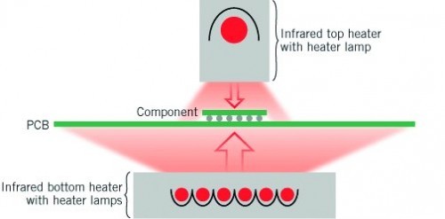
 Fig. 2: Schematic representation of a repair processThisknowledge canalsobe used to achieve success in electronic production. On the one hand, at least in large-scale production, attempts are being made to achieve an (almost) error-free method, because the clever manager knows that repairs are far more expensive than the actual production. A long time ago, American military officers postulated that a soldered joint in production cost just $ 0.48, while a repair of such a joint cost between $ 7.00 and $ 15.00. This discrepancy has long since disappeared. This discrepancy has long since shifted, not only because we have to factor in inflation, but also because products have changed a lot.
Even the accounting downtime costs of several 1000 €/h when a line is at a standstill are now antiquated and probably only apply to a few very slow lines. In large-scale production - such as for cell phones - a finished soldered circuit board is expected every ten to twenty seconds. Particularly small and particularly large components present the dear workers with ever greater problems and this is where studying Skinner's teachings pays off.
Instructions on how to do everything 'correctly' when reworking can be found in abundance on the Internet and you have to look closely to separate the valuable from the advertising. This is where the teacher comes into the picture, either pursuing their own interests and wanting to sell something or offering genuine help.
The teacher can now pursue a strategy that explains the process step by step or assume that a certain amount of prior knowledge is available and then warn of possible mistakes.
First of all, the error must be found and located. To do this, you need a definition of the defect, because simply embellishing a solder joint that the inspection does not like is not only expensive but also usually impairs its quality and durability. In the event of a functional failure, there are two alternatives: disposal or repair.
Assuming quality control has acted well and intelligently, the PCB ends up in the repair loop. Now it depends on how this is organized. In smaller companies, someone pulls the hot soldering iron out of the holder or starts up the repair station. In larger companies, it is hoped that the entire process is now organized down to the smallest detail.
Nevertheless, errors can still occur. Let's assume that a large BGA has to be replaced without the same component being reused immediately. Experts know that a certain frequency of errors made here can be tabulated. Let's take a look at some of them:
Discarding or bending the component
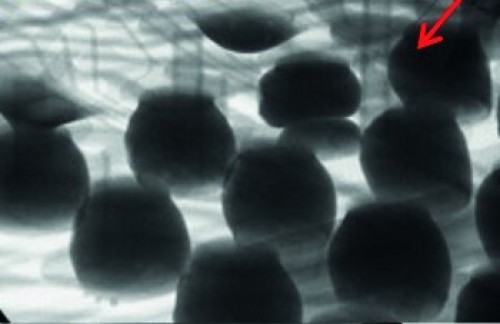
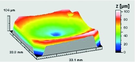
 Fig. 3: Pillow defect in the X-ray imageThethinner the component body, the more often this occurrence is noticed. Sometimes the corners and edges bend upwards, other times downwards. In the former case, so-called 'pillow defects' often occur, which then represent very insecure connections. Otherwise, bridges or crushed paste deposits are the result. Both are probably not welcome results, as a repeat repair is usually out of the question because the number of thermal excursions is pushed to the limit anyway.
When bending, you look at both the PCB and the component. The PCB should be well supported and heated to approx. 100 to 120 °C from below (difficult with assemblies assembled on both sides). If possible, the area where the component is positioned on the other side should receive a further 20 to 40 K, i.e. be heated to 120 °C.
The component is then brought to the required reflow temperature using convection (nitrogen) if possible. Infrared lamps are also used, occasionally in addition to convection. The heat increase should be quite slow in order to keep the temperature the same over the entire component. The aim is to achieve a maximum of around 10 K as ΔT over the entire surface of the BGA. Reflow then takes place at around 20 to 30 K above the liquidus of the solder alloy used. The time should be kept short. The aim here is around 60 seconds.
One of the reasons for such reflow profiles and specifications has to do with the flux and wetting. At higher temperatures, the active part of the flux evaporates or decomposes or reacts with metal oxides so that ultimately no more acids are present. However, as the pillow fault, for example, indicates a lack of wetting, the consumption of the flux would be one of the indicators.
The use of nitrogen is an aid here. But choosing the right flux is a tricky business. On the one hand, you want active behavior, but this usually comes at the price of disgusting and dangerous residues that are very difficult to remove under large BGAs.
A larger paste depot would be a good idea, but here too you have to consider that it is a balance game between crushed paste, bridges and short circuits and a proper solder joint instead of the pillow phenomenon.
Before applying paste, you must ensure that the landing surfaces are planar, otherwise you will not achieve an even depot. Whether you use mini stencils, dispensers or jetting methods to apply the paste depends on your skills, the constellation on the PCB and the possibilities in your company.
 Fig. 4: Warping and deviation in the z-direction of a BGA
Damage to neighboring components due to the effect of heat
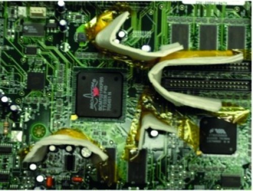
 Fig. 5: Protection against overheatingModernassemblies are exceptionally densely populated with many large and thermally sensitive components. As it is almost impossible to limit the heat to the component being worked on, care must be taken to ensure that no collateral damage occurs during the repair, which would then negate all the effort involved.
You immediately notice that certain aspects of the repair are contradictory. On the one hand, you want to protect the components and their solder joints against thermal stress, on the other hand, you heat the (entire) assembly to 100-120 °C so that only minor distortions are experienced. Ageing of the solder joints reduces their reliability and some components can be damaged both on the plastic body and internally. Information and test methods can be found at the IPC or the ZVEI.
As a countermeasure and to keep the air or nitrogen flow away from neighboring components, covers are fitted. These are often special sheet metal parts that are well adapted. Sometimes heat-resistant Kapton adhesive tape is used, but this requires a certain amount of dexterity on the part of the personnel.
Electrostatic charge
A few more comments on an issue that is often overlooked. Electrostatic discharge often causes unnoticed damage to sensitive components. It is therefore worth considering how the product is protected during the repair cycle. It's not just about the worker, but about the entire process. Convection with dry gases leads to a charge, which can then cause damage when the product is lifted off the appliance. As the distances in the components become smaller and smaller and the voltage used during operation has steadily decreased, even small and very brief current discharges are dangerous.
What helps against this is earthing, but this must be routed via high resistances and must be maintained without interruption, because the electrical devil strikes exactly where there would be an interruption in such a chain.
Literature and notes:
IPC J-STD-075
B. Wettermann: Top 5 BGA Rework Challenges to Overcome (2016), Proceedings of SMTA International, 2016, Rosemont, IL, USA
Rework of Electronic Assemblies, ZVEI - Zentralverband Elektrotechnik und Elektronikindustrie e. V., German Electrical and Electronic Manufacturers' Association, PCB and Electronic Systems Division, Lyoner Strasse 9, 60528 Frankfurt am Main, Germany
B. Wettermann: Multiple Methods for Applying Paste Flux or Solder Paste for BGA Rework
References:
[1] Max und Moritz, eine Bubengeschichte in sieben Streichen, by Wilhelm Busch; Fifty-third edition; 1906, Munich, Verlag von Braun und Schneider
[2] Burrhus Frederic Skinner (1904 to 1990) www.biography.com/scientist/bf-skinner

![For those who play evil tricks do not pay attention to the teacher [1]](/images/k2/f54f5eacd0a6f73edff93d6d704e627a.jpg)
