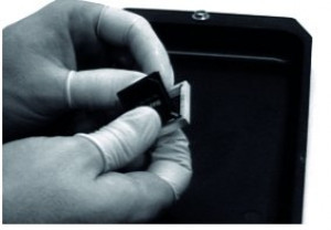
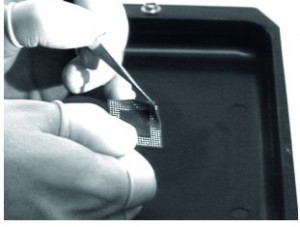
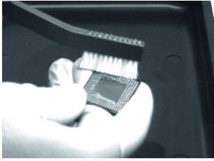
Once again, your carefully trained repair person has left a few balls of the large BGA on the circuit board when lifting it off - or was it someone quickly trained because you had an acute shortage of personnel? But you were lucky: the expensive component still works.
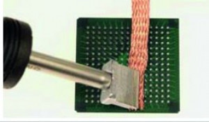
So the component has to be saved so that production costs don't rise too much. What's more, new ones are hard to come by. If the thing was also underfilled, which is usually the case with mobile applications, your specialist will first use a heated tool to score and remove the epoxy resin. To ensure that the circuit board remains undamaged during this process, however, this procedure requires a high level of expertise and very careful training.
Only when the resin has been successfully removed can the actual reflow process begin. Components with a high pad density on the bottom and multiple patterns on the top cannot be lifted off with traditional vacuum tools. Instead, tweezers (some of which are already integrated into the reflow nozzle), multiple suction cups or even mechanical levering are used.
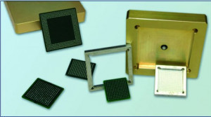
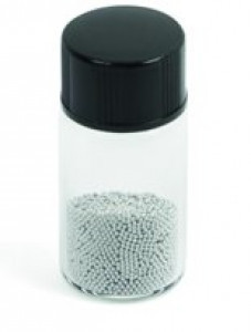 Fig. 4: BGA balls with 0.6 mm Ø - different alloys/materials, large selection of diameters (l.)But how do you re-ball correctly? Putting on individual balls with a shaky hand makes no sense, if only because of the subsequent soldering. You browse through the documentation and find references to such valuable documents as IPC-7711-[GA Reballing Procedure (Polyimide Solder Ball Stencil Carrier)] - or you look for help on the Internet and come across a tangle of contradictory advice spread by more or less talented experts.
The simplest and most straightforward solution to your trusty problem is to choose a service you trust and let them get your BGA back up and running. This may seem expensive at first glance, but if you only need to repair a few BGAs, it may be cheaper than buying the necessary machines, accessories and materials and having someone trained on top of that. There are plenty of services out there and some are well established.
The other option, of course, is to keep everything in-house. This gives you total control, but also responsibility for the outcome.
So how do you pull your head out of the noose? The decision is not an easy one, as it depends on several factors. There are a number of different BGAs, each of which needs to be treated differently.
- Ceramic BGA (CBGA)
- Plastic laminate BGA (PBGA)
- Dry-Clad: A proprietary epoxy-based laminate from IBM
- Polyimide: A type of plastic laminate
- Bismaleimide triazine epoxy glass: Also known as BT epoxy glass
- Tape BGA
- Metal BGA (MBGA) as a related class
- PoP Package Types
- LGA Package Types
- QFN Package Type
- Flip chip
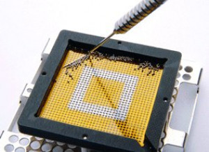 Fig. 6: Inserting the balls into a stencilAllhave slightly different conditions with regard to the type and size of the solder balls to be used, the solder alloy, the arrangement grid and the temperature conditions imposed by the material and the design of the component and the assembly. It should not be forgotten that the balls have to be soldered on, which is why either flux or paste is used.
The procedures also vary depending on how many repairs need to be carried out. Smaller volumes - let's say less than a few hundred pieces - obviously present a different set of problems than mass production as used in the original manufacture of BGAs.
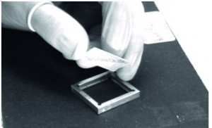
On 'youtube' you can probably admire the best-known method and watch how someone arranges the small beads in a template. This is usually started with a pouring process and then all the beads that have not fallen into one of the holes in the template are removed using some kind of procedure, such as a brush. With this saturation, you hope to have caught them all. However, it is absolutely essential to check this carefully, preferably under a stereo microscope, because as luck would have it, the method does not always work.
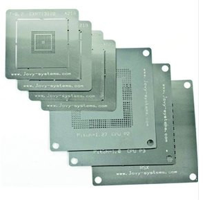
As far as the small stencils are concerned, there is of course a wide range of variation as the components have very different 'balls' and even vary greatly in their dimensions.
As a special feature, some stencils are made of non-conductive material. In one case, it consisted of a semi-elastomeric material and was made from a 1-component cold-curing latex binder using synthetic rubber or a 1-component work-hardening styrene acrylic emulsion binder. A thermally conductive fine powder was used as a filler. The crumb rubber powder (produced by an environmental grinding process) came from car tires (synthetic rubber) with a particle size of up to 0.2 mm. These stencils are then simply left between the component and the PCB after reflow. According to the announcements in the relevant patents, they also serve as spacers or, if they stick, as a kind of 'underfill'.
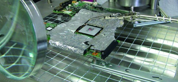 Fig. 7: BGA prepared for reflow - thermal cover and thermocouple (Toolboom)
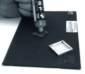
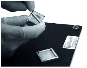
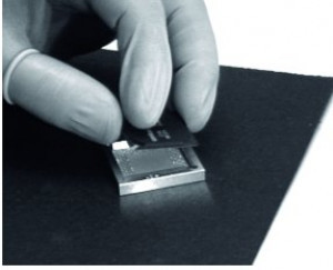
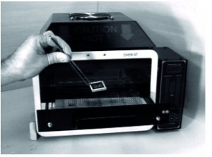
Prepared templates filled with balls can also be found on the market. Also known as 'preforms', these tools are perhaps the simplest and clearest way to understand the various steps required. Patented by Raychem Corporation, it is offered by Winslow Automation, Inc.
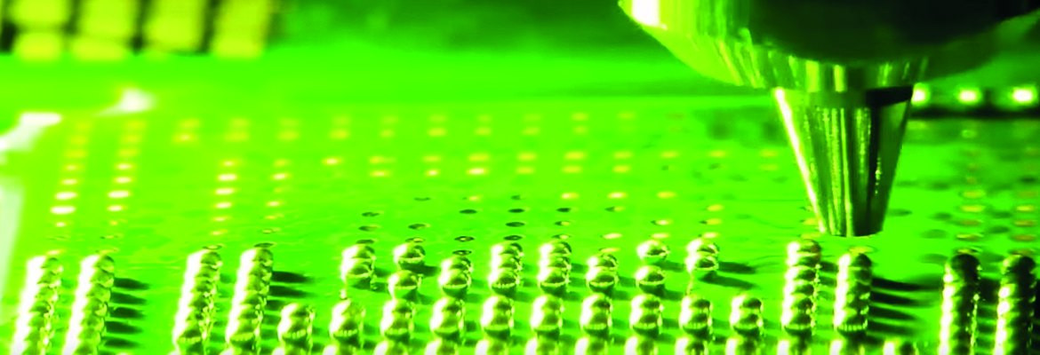 Fig. 8: Reballing with jet printing and laser reflow
A completely different method does not use balls, but produces them directly on the component by melting paste deposits that have been set using 'jets'. The melting is done by a laser. Obviously this is not the cheapest version and depends heavily on the power of the jet device. Perhaps it is worth adding another consideration. The number of thermal excursions for the component should not be neglected. There is 1. the original soldering, 2. the soldering onto the assembly, 3. the desoldering, 4. the cleaning of the soldering surfaces, 5. the re-soldering of the balls, 6. the re-soldering onto the assembly ... No wonder the mountains of electronic scrap are getting higher and higher.
Literature and notes:
IPC 7711 Rework, Revision: Date: 10/11, BGA Reballing Procedure, Polyimide Solder Ball Stencil Carrier
L.L. Shu et al: Board Level Failure Analysis and Demount Challenges for Package-on-Package, Proceedings of SMTA International, Sep. 25-29, 2016, Rosemont, IL, USA
P. Karydopoulos et al: Structure of Ball Grid Array/Permanent Semi- Elastomeric Thermally Conductive Crumb Rubber Reinforced Bituminous Stencil/Printed Circuit Board Interconnects, Conference Paper - November 2014
Ross Dillman, BGA Reballing, ACI Technologies, Inc.
http://www.solderquik.com
References:
[1] Ironic remark by a German carpenter in Canada - well known to the author personally and to regular, attentive readers of his column.

![No one has ever fooled us when it comes to tinkering [1]](/images/k2/f07d5047bdfa0c2580b3276fb0b042f4.jpg)
