One of the longest used final layer systems in the PCB industry is ENIG (electroless nickel/immersion gold). Particular attention should be paid to avoiding surface corrosion.
It is in the nature of the deposition reaction that the dissolution of nickel is required for the gold layer to provide the necessary electrons. Under normal conditions, this does not lead to problems with the solderability or bondability of the ENIG final layer. However, special attention should be paid to avoiding surface corrosion, as this can have a particularly critical effect on the soldering and bonding behavior of the layer.
One aim of the development of immersion gold electrolytes was to reduce the dissolution reaction as far as possible and thus minimize local attacks on the nickel layer. Various working groups have investigated the dissolution reaction during gold deposition and the various influencing factors. The aim of this article is to show
- how ENIG corrosion can be evaluated and determined during development
- which types of corrosion are actually critical for the application and
- how the problem of ENIG corrosion can be avoided by selecting the right electrolyte.
Introduction
The ENIG end layer system still covers a major part of the volume of the overall end layer market as it provides a reliable end layer that is both solderable and Al-wire bondable. Over the years of market presence, it has proven to be a robust process that allows for reliable solder joints. However, as an immersion step is used in the gold deposition process, the dissolution of nickel is unavoidable. This poses a potential risk of soldering defects if the process is not operated in a controlled manner. This nickel dissolution is typically referred to as ENIG corrosion, or in special cases as 'black pad'. The term is particularly applicable when the corrosion attack of the gold bath attacks the nickel layer homogeneously on the surface. In this case, the nickel layer appears dark or black after the gold layer has been removed.
In some cases it has been observed that the formation of the intermetallic phase (IMP) can be disturbed at these points, which in turn can lead to a weakening of the solder joints. For this reason, the assessment of ENIG corrosion is a control parameter to assess the quality of the final layer.
Depending on which types of nickel and gold electrolytes are used, the type and intensity of corrosion attack can vary. For example, there are small, individual attacks that do not necessarily interfere with the formation of the IMP due to their small size and are therefore not considered critical(Fig. 1, top right).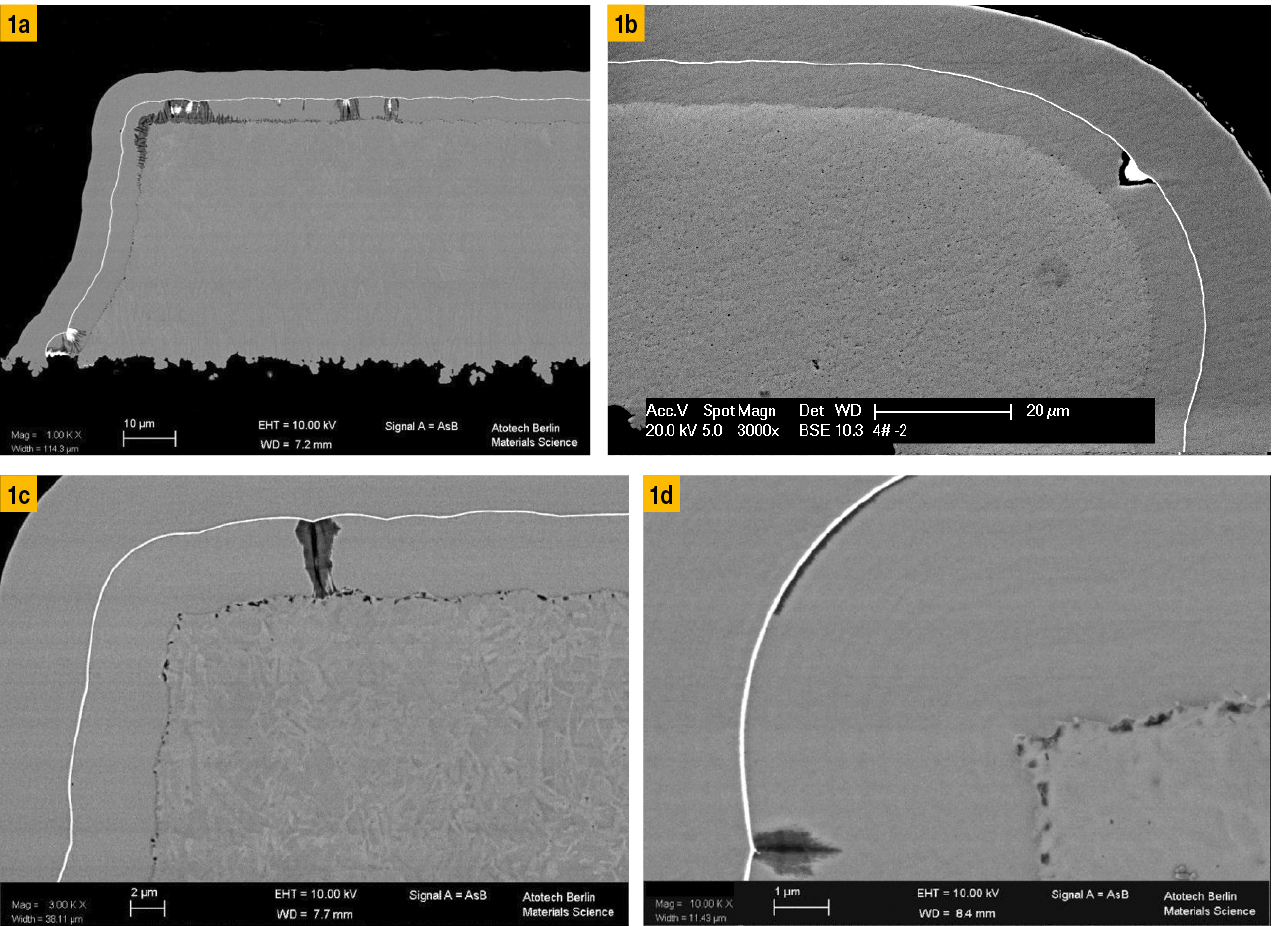 Fig. 1: Example images of typical corrosion events on ENIG layers, a) Large-area corrosion through the entire nickel layer (SEM image with protective layer), b) Individual corrosion events (SEM image with protective layer), c) Corrosion through the entire nickel layer (SEM image with protective layer), d) Surface corrosion (SEM image with protective layer)
When comparing the different types of corrosion, it becomes clear that the goal for the development of new gold electrolytes can only be to minimize the attack of the gold bath on the nickel layer as far as possible.
Corrosion evaluation in product development
One of the main requirements during the development of new plating electrolytes, apart from the selection of the bath composition, is to introduce an objective and statistically reliable evaluation method in order to assess the performance of the final layer and to be able to recognize positive or negative trends. During development at Atotech, a broad catalog of requirements was therefore implemented that must be fulfilled before a process is ready for the market. These criteria include requirements for the bath properties, the process control and also the properties of the deposited final layer.
The requirements for the final layer, such as optical appearance, etch resistance in the SIT process, layer thickness distribution and soldering and bonding behavior, are assessed on the basis of internal criteria and international standards such as the IPC. In the development of ENIG processes, the evaluation of corrosion is of particular importance. Here, a balance must be struck between time expenditure, statistical significance and objectivity of the evaluation. In order to introduce an evaluation system that allows corrosion to be evaluated objectively and independently of the processor, an evaluation table was created in which the number and depth of corrosion events can be recorded simultaneously. To ensure that the results are statically relevant, it is recommended that at least 2 different areas on the PCB and at least 2 drill holes in each area are examined.
Another point to consider is the decision as to whether the examination should be carried out using an optical microscope or an SEM. There are a number of advantages and disadvantages of the individual methods.
|
Light microscope |
SEM |
|
|
Examination effort |
Low |
High |
|
Size of the examined area |
Can be large due to the simplicity of the method |
Acquisition of individual images necessary |
|
Examination time |
Fast |
Slow |
|
Resolution |
Low |
High |
|
Detection of small defects |
Requires a lot of experience due to the contrast |
Simple |
If you compare the two methods, it becomes clear that compromises are unavoidable. Examination with a light microscope allows large areas to be examined comparatively easily and quickly and a light microscope is available almost everywhere.
In contrast, the effort required to take images with the SEM is significantly higher and, as the device is considerably more expensive, availability may be lower. On the other hand, the higher resolution of the SEM allows even small defects to be detected that cannot be captured with an optical microscope.
The current version of IPC 4552A contains a description of the corrosion examination, which leaves some room for interpretation as to how the examination should be carried out. The aim of the current revision is therefore, among other things, to define more clearly the number and location of the areas to be examined and thus enable an assessment of whether a printed circuit board is acceptable with regard to ENIG corrosion.
For the development of coating processes, on the other hand, it has been shown that a systematic and more comprehensive method is required in order to be able to recognize gradations. Therefore, typically at least 2 locations on the PCB are examined with at least four drill holes each. In order to enable as objective an evaluation as possible and to minimize the influence of the operator, an evaluation table was created in which the corrosion is documented in terms of number and depth.
Various corrosion categories are defined and subdivided according to depth in the nickel layer from 0 to 20 %, 21 to 40 %, 41 to 100 %, > 100 % and surface corrosion. This method allows the corrosion events to be quantitatively recorded and evaluated in order to compare and assess different process conditions.
Corrosion in the 0 to 20 % range includes all corrosion events that penetrate the nickel layer at a depth of 0 to 20 % of the layer thickness. Such corrosion events are typically not particularly critical, as the attack on the nickel layer is low and the influence on solder wetting and the formation of the intermetallic phase (IMP) is low. In the 21 to 40 % range, the corrosion sites that penetrate 21 to 40 % of the nickel layer thickness are recorded. This type of corrosion is also rather uncritical as long as the number of events is low and sufficient nickel layer remains for the formation of the intermetallic phase. More critical are the corrosion events that penetrate the nickel layer in the range of 41 to 100 %, as these may penetrate through to the underlying copper and thus impair the barrier function of the nickel layer. In this case, there is a risk of copper migrating to the surface and weakening the solder or bond connection.
In addition to this classification, there is another form of corrosion that is recorded: surface corrosion. This typically consists of a sponge-like structure on the surface of the nickel layer and does not go into depth. Due to the sponge-like structure of the nickel surface, the nickel layer appears black after removal of the gold layer, which has led to the frequently used term 'black pad'. As this type of corrosion can be distributed over larger areas with a diameter of several µm, it carries an increased risk of leading to solder separation and wire bonding defects. As a larger area along the nickel/gold interface may be affected, the formation of the intermetallic phase may be disturbed or, in the case of bonding applications, the bond between the nickel and gold layers may be weakened. This creates a kind of 'predetermined breaking point' at which the gold layer can detach from the nickel layer [1].
When is an optical microscope no longer sufficient?
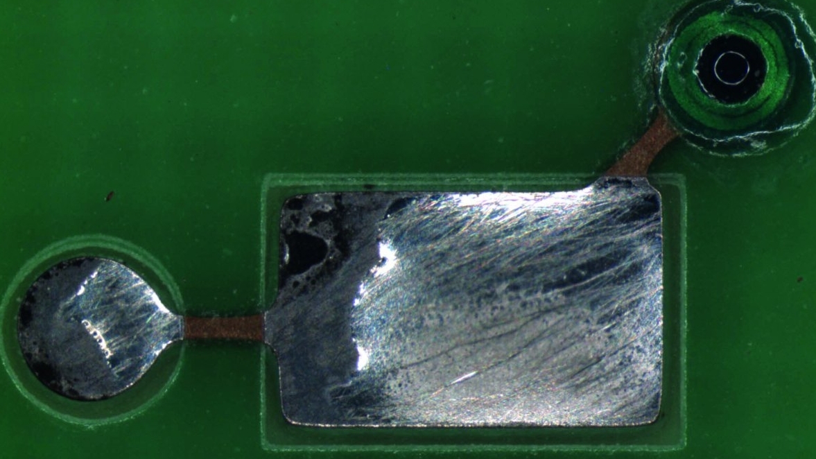
In order to enable a reliable and representative evaluation of the corrosion, which allows a statistical assessment of test results, the evaluation method described above is used in internal product development. Typically, a combination of light microscope and scanning electron microscope (SEM) is used, in which the light microscope is used for the overview examination and the SEM for detailed examinations with higher resolution. This method allows a much more detailed assessment of the coating properties than the procedure described in IPC 4552A. If the evaluation is carried out exclusively with the light microscope, there is a risk that the critical surface corrosion can be overlooked due to the low resolution of the method and the low penetration depth of the corrosion in the cross-section. This can even happen during examination using SEM if the contrast is too low and no nickel protective layer has been applied for the cross-section preparation. In such cases, it is possible that a final layer that has been assessed as 'corrosion-free' can lead to soldering defects or adhesion problems in the bond joint. Some typical defect patterns are summarized in Figure 2. Entnetzte Oberfläche, b) Bond-Abheber auf der ENIG-Schicht, c) Vollständig benetzte Oberfläche, d) Detail-Bild der Oberfläche nach Abheben der Goldschicht durch den Bond-Draht") Fig. 2: Exemplary images of solder and bond defects on ENIG layers, a) Dewetted surface, b) Bond lifter on the ENIG layer, c) Fully wetted surface, d) Detail image of the surface after lifting of the gold layer by the bond wire
Fig. 2: Exemplary images of solder and bond defects on ENIG layers, a) Dewetted surface, b) Bond lifter on the ENIG layer, c) Fully wetted surface, d) Detail image of the surface after lifting of the gold layer by the bond wire
In the areas of the bond lifter, it can be seen that the gold layer has been completely removed although there is no obvious damage to the underlying nickel layer in this area. If you compare the two soldered surfaces, the defect area where the solder has been removed shows a dark discoloration of the underlying nickel layer. For a better understanding of the defect, high-resolution SEM images of the defect areas were taken in cross-section (see Figs. 3, 4 and 5).
Comparing the images in Figures 3, 4 and 5, it is clear that the corrosion expands over wide areas, but does not penetrate into the depth of the nickel layer. On the contrary, the average depth is often no more than 100 nm. Such defects are very difficult to detect under a light microscope and require examination with a high-resolution SEM. The application of a nickel protective layer can also help to obtain a better contrast and thus avoid the misinterpretation of artifacts from the cross-section preparation. This type of surface corrosion poses a high risk and can lead to defects in solder wetting and bond adhesion.
 Fig. 3: Cross-section of defect structures on an unsoldered surface
 Fig. 4: Cross-section of wetted areas at the defects with intermetallic phase
 Fig. 5: Cross-section of wetting areas at the defects without intermetallic phase
Solution for avoiding ENIG corrosion
In order to avoid ENIG corrosion and to minimize the corrosive attack of the gold electrolyte, various types of gold electrolytes have been developed in recent years. From the first generation, in which deposition took place entirely via the exchange reaction between nickel and gold, to the second generation, which already contained additives with slight reductive properties, to today's third generation. Third-generation gold electrolytes contain reducing agents and work with a mixed reaction of immersion and autocatalytic deposition. Such baths have already been used in the past for nickel-palladium-gold deposition and have now been further developed for use in ENIG. Aurotech G-Bond 2 is such an electrolyte - it offers a consistent result with excellent corrosion behavior for both ENIG and ENEPIG. Extensive tests were carried out in order to be able to make a reliable statement about the corrosion behavior. The corrosion was recorded and categorized according to the following criteria based on the evaluation carried out in Table 2:
- Level 0: no corrosion events
- Level 1: less than 10 events that are no deeper than 20% - or a single event with a depth of less than 40%
- Level 2: all other observations
- Level 3: 10 or more events and more than 5 deeper than 40 % - or surface corrosion with an extent of more than 30 % of the image
With this type of classification, it is possible to assess the corrosion representatively and quantitatively. In order to make statistically relevant statements, typically seven areas per drill hole are examined at six different points on the PCB. In order to be able to make an overall statement for the PCB, the classification carried out previously is further classified on the basis of the respective percentages. The following criteria are used for this:
- Class 0: no corrosion
- Class 1: more than 60% of the areas examined have a classification of 0 or 1
- Class 3: more than 40 % of the areas examined have a classification of 3
- Class 2: all other observations
This assessment also records the fact that surface corrosion is particularly critical for an ENIG final layer. Using this method, a study was carried out to assess the current situation at PCB manufacturers in the USA, Europe and Asia. First and second generation gold baths in mass production were compared with the results of the third generation Aurotech G-Bond 2. For this evaluation, 7 areas of 10 drill holes per PCB were examined. For Aurotech G-Bond 2, only a classification of 0 is observed, which correlates with a classification in class 0.
|
Number of corrosion events |
|||||||
|
Sample number |
Pad/PTH number |
0-20 % |
21-40 % |
41-100 % |
100 % |
>100 % |
Surface corrosion |
|
1 |
1 |
3 |
5 |
1 |
0 |
0 |
0 |
|
1 |
2 |
2 |
3 |
4 |
0 |
0 |
0 |
|
... |
... |
||||||
A comparison of the data from such an evaluation of the various gold electrolytes used in production worldwide shows that there is a clear trend towards improved corrosion behavior across the different generations of gold baths. Figures 6 and 7 show the proportions of corrosion levels and classes for a first-generation gold bath (A), second-generation gold baths (B, C, D) and third-generation gold baths (E). Even though very good results can already be achieved with the second-generation baths, the best and flawless results are achieved with the latest third-generation gold bath.
Summary
ENIG corrosion is one of the most discussed topics for ENIG final layers in the PCB industry and there are ongoing efforts to define and establish clear acceptance criteria. Therefore, one of the main goals in electrolyte development is to reduce the corrosion attack of the gold bath as much as possible. The evaluation method presented in this article allows a statistical evaluation of the data and a quantitative comparison of different final layers.
 Fig. 6: Overview of the proportional distribution of the different corrosion classes across the gold bath types
 Fig. 7: Overview of the proportional distribution of the different corrosion levels across the gold bath types
 Tab. 3: Corrosion evaluation for Aurotech G-Bond 2
If the corrosion results are compared with the solder and bond reliability of a final layer, it becomes clear that surface corrosion is the most critical type of corrosion for the connection of component to PCB. On the one hand, because it can disrupt or completely inhibit the formation of the intermetallic phase, and on the other hand, because it is easy to overlook, especially when examined with an optical microscope. For this reason, it is recommended to use a combination of optical microscope and SEM for corrosion analysis. The evaluation method shown here was also used to compare the corrosion result of a new third-generation gold bath with conventional gold baths in mass production. It can be seen that no corrosion is recognizable in the cross-section of the latest gold bath. As the investigation focused in particular on the evaluation of the nickel-gold interface, surface corrosion can also be completely ruled out.
References
R. Schmidt; M. Zwanzig; M. Schneider-Ramelow: Causes and avoidance of the black pad defect when soldering SMDs (PLUS 5/2013, 1080-1087)
