
Dispersion coatings have become an integral part of the electroplating landscape. Speakers Prof. Timo Sörgel from the Center for Electrochemical Surface Technology at Aalen University of Applied Sciences and Jürgen Meyer, De Martin AG, CH-Wängi, explained the basics of the process and presented the opportunities for future applications in a ZOG seminar on October 26, 2021.
 Fig. 1: Definition of dispersion depositionInthe new rooms of Aalen University of Applied Sciences, participants were able to gain an overview of the extensive topic from a broad program of theory and practical laboratory examples and learn about the latest developments.
Dispersion layers are galvanically deposited on a substrate. Non-soluble solids (dispersoids) are evenly distributed in the electrolyte and incorporated into the electrically conductive matrix (binding phase) (see Fig. 1).
The applications of dispersion layers are diverse and are mainly found in technical and medical applications, e.g. in dental tools or bone cutters, in components of textile or plastic injection molding machines, on cylinder head surfaces or saw wires. The interaction between matrix and dispersoids is ultimately responsible for the properties of the dispersion layers. The synergetic interaction of matrix and dispersoids leads, for example, to
- Increased coating hardness as protection against abrasive wear
- Influencing the surface structure, e.g. increasing the coefficient of friction, matting the surface
- abrasive, machined surfaces through the installation of abrasive media
- dry lubrication for applications requiring freedom from oil or grease, emergency running properties, optimization of mixed friction conditions
- anti-adhesive surfaces such as hydrophobic or oleophobic surfaces, anti-fouling layers, demolding layers, etc.
- self-healing surfaces with e.g. improved corrosion protection
- modified matrix structure
The first patent for dispersion deposition dates back to 1905 and was published in New York. It describes a process in which the substrate is positioned horizontally in the electrolyte and the solid particles trickle from above during deposition as if from a salt shaker and are thus also deposited (Fig. 2). Today's applications place high demands on the surfaces, so that the deposition techniques have been improved accordingly.
 Fig. 2: From the first patent on dispersion deposition
Suitable matrix systems can be produced from common electrolytes as pure metals or alloys.
- Electroless and galvanic nickel
- Iron, (cobalt)
- Copper, silver, gold
- Zinc, (cadmium)
- Tin, (lead)
There are several solids for dispersoids for a wide range of applications.
Typical particles are for example
- Hard materials: Diamond, SiC, B4C, Si3N4, TiN (galvanic layers)
- Inorganic solid lubricants: MoS2, WS2, h-BN, graphite, CFx
- Organic solid lubricants: PTFE, other fluorinated polymers (particle sizes generally < 1 µm)
|
Application/ coating properties |
Ni-P low Phosphorus |
Ni-P medium phosphorus |
Ni-P high phosphorus |
Ni-P-PTFE NiP-hBN |
Ni.P-SiC Ni-P-diamond Ni-P-boron carbide |
|
Wear resistance moderate attack |
• |
- |
- |
- |
|
|
Wear resistance severe attack |
- |
||||
|
Corrosion resistance ASTMB 117 |
- |
||||
|
Solderability |
- |
||||
|
Friction coefficient reduction/anti-adhesive |
- |
||||
|
Increase in friction coefficient |
- |
||||
|
Resistance alkaline media |
- |
- |
|||
|
Resistance to acidic media |
- |
||||
|
Optics/gloss |
- |
- |
|||
|
Machinability Turning |
- |
||||
|
Non-magnetic |
- |
 Fig. 3: Strategies for homogeneous particle incorporation Diamond, a very hard and chemically harmless material that is available in a wide range of grain sizes, is suitable for many technical applications. Boron nitrite (h-BN) is also known as white graphite, which, unlike graphite, is not conductive. An interaction of chem. Nickel as a matrix with dispersoids has a wide range of applications due to its properties and the simultaneous use of conformal deposition. Table 1 shows some coating systems and their properties. Depending on the requirements placed on the dispersion layer, the particles are used in different sizes and intercalation volumes and the deposition processes are adapted accordingly. While the sedimentation of the particles was utilized in the first patent, in today's processes it is important to keep the particles suspended in the electrolyte in order to ensure uniform deposition. The technical possibilities of electrolyte circulation for the dispersion of solid particles are shown schematically in Figure 3. To prevent sedimentation, electrolyte circulation pumps are used, supported by additional air injection. The larger the electrolyte volume, the more difficult the homogenization.
Following the law of nature that the energy of a closed system is always the same, but can be distributed differently by spontaneous processes, particles in a solution tend to agglomerate. This behavior is more pronounced with very small particles, as the ratio of large surface area to small volume is energetically unfavorable. The particles are held together in the agglomerates by so-called van der Waals forces. The inclusion of agglomerates in the dispersion layer is undesirable because they have a negative effect on the layer properties. Strategies for deagglomeration have therefore been developed.
| Electroless nickel | Galvan. Nickel | Chromium III | |
| Deposition rate | 0.17 - 0.35 j.Jm/min | 3-5 j.Jm/min up to 10 IJm/min | 1 j.Jm/min |
| Layer | Alloy layer with 3-12 % P | Ni alloy layer with P | Cr |
| Layer thicknesses | up to 30 IJm [up to 100 IJm] | 50-200 IJm [up to 1000 IJm] | |
| Solids | Diamond; SiC; B4C PTFE; hBN | Diamond; SiC | Diamond; Al2O3 |
| Particle sizes | 1-25 1-1m [up to 50 1-1m] | up to 500 1-1m | < 21-1m |
| Component geometry | complex | simple | simple |
| component size | small | large | small |
| Contour accuracy | high | low | low |
Mechanical methods for deagglomeration (shearing by agitators, application of ultrasound, high-pressure homogenization) lead to an equilibrium setting in the electrolyte, but the formation of agglomerates is not prevented. Steric or electrosteric stabilizers, which lead to a reduction in van der Waals interactions, are more suitable. Here, dispersant molecules are introduced into the solution, which form a hydrate shell of approx. 20 µm around the particles so that the particles no longer "see" each other and thus do not form agglomerates. During deposition, the stabilizer must be stripped off again. As this process is dependent on the pH value, this is achieved using a sophisticated buffer system. Alternatively, the particles can be encapsulated by surrounding them with sol-gel layers.
There are many possible applications for dispersion coatings, with a particular focus on corrosion and wear protection or the targeted adjustment of friction coefficients. From the many examples shown in the seminar, only the possible replacement of hard chrome by dispersion coatings will be shown here. Alternatives to hard chrome are desirable from different perspectives. The REACh requirement to replace chromium VI has long been known. There are other arguments against the use of hard chrome.
In the case of electroless nickel in particular, the possibility of increasing the hardness after heat treatment is used, so that hardnesses reach 950-1050 HV depending on the phosphorus content (see Table 2). Despite the high hardness of heat-treated electroless nickel coatings, their wear values are 4-10 times higher than those of hard chrome. If suitable particles are also incorporated into the electroless nickel coating, hardness and wear can be further increased so that the properties of the coatings are comparable to hard chrome and can serve as a hard chrome substitute. Example in Table 3.
 Fig. 4: Plant technology for electroless nickel dispersion coatings
The schematic representation of a system for the deposition of electroless nickel dispersion coatings shown in Figure 4 is taken from the US patent (US6123989A, Schlafhorst). Stainless steel is the preferred container material and the container is heated indirectly via a water jacket. The container tapers towards the bottom so that the dispersoids are pumped in a circle together with the electrolyte; in addition, the electrolyte and dispersoid are continuously mixed. The product is fed into the electrolyte on a rotating rack. The system design together with an optimally dimensioned bath volume ensures trouble-free dispersion separation.
| layer | Hardness *) | Wear **) | Coefficient of friction |
| Hard chrome | 1000-1050 | 4-10 | 0,2 |
| Electroless nickel ***) | 500-750 | 6-12 | 0,35 |
| Electroless nickel n. Heat treat. ***) | 950-1050 | 6-21 | |
| Electroless nickel - PTFE | 0,12 |
As part of the seminar, the world's first pilot plant for the continuous production of composite electroformed metal foils for battery technology was presented at Aalen University. The composite electroforming process combines the classic methods of electroforming and dispersion deposition. The resulting foil takes over the mechanical and electrical contacting as well as the current collecting function of the metal. This eliminates the problems of previous films, namely the compromise between the non-conductive binder and the limited mechanical stability, thanks to the carbon used. The resulting films are structured and porous, as shown in Figure 5.
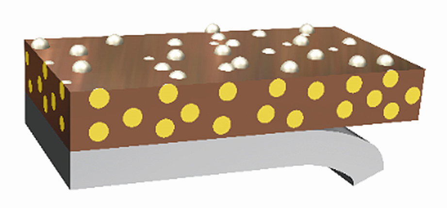
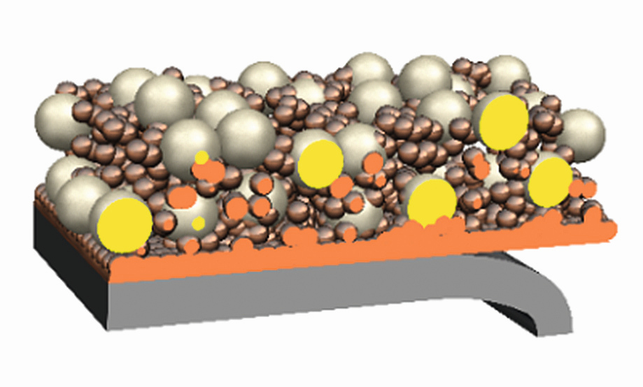
Fig. 5: Comparison of compact films (left) according to the state of the art to structured composite galvanoformed film (right)
Figure 6 shows a schematic diagram of the developed and patented process. Water, electrolyte salts and active materials are dissolved and mixed. The substrate is applied to a rotating cylinder, on which the particles are deposited into the metal matrix during rotation. The resulting film is then separated from the substrate. The film is rinsed and dried and can then be further processed.
 Fig. 6: Schematic representation of the film production system
 Fig. 7: Prototype system, photo: Oliver Kesten
The prototype system shown in Fig. 7 is used to produce films and profitability calculations are carried out using the parameters obtained. There are already collaborations with companies that will implement the process industrially. This is an example of how research results do not end after basic research, but how development is continued right through to application in industry.
