... and the quality of the coating
The importance of controlling the current flow
When electricity is converted from alternating current to direct current, the current flows in waves. Just as a light powered by such a current would flicker, electrochemical processes are also affected, either slowing down or stopping, even if only for milliseconds - and imperceptible to the human eye. This article shows how the fluctuation range of these waves - high or low - has a significant impact on homogeneity and throwing power, coating quality and the resources required for metal finishing.
Numerical measured values show average voltage
The voltage reading on a rectifier panel is only an average value. What really counts is the percentage of the nominal voltage that is actually used. For example, 7.3 V of an 18 V rectifier corresponds to 40.4 %. The graph in Figure 1 shows the reality behind this average and what actually happens. Here we see the current output through a silicon controlled rectifier (SCR) or thyristor at 100% (in blue) and 40.4% (in dark blue). Each wave, or ripple, lasts about 3 milliseconds. If the output voltage is 100 % of the nominal voltage, the ripples are low. But such high voltages would produce currents too high for hard chrome plating - over 1000 to 1200 ASF (amperes per square foot). However, at a value below 100%, the peaks and troughs of the power supply become more pronounced. So at an average value of 40.4%, the current ripple fluctuates between 0 and about 840 ASF approximately every 3 milliseconds - a huge variation that affects plating performance.
 Fig. 1: SCR rectifier waveforms at different output voltages
 Fig. 2: Theoretical waveforms of SCR and switched-mode rectifiers at different nominal output voltages
Silicon-controlled rectifiers (SCR) reduce ripple somewhat by using expensive filters that promise, at best, a ripple of 5% at 100% of the device's nominal voltage (which deteriorates as the output voltage decreases). A switching rectifier from KraftPowercon in Surte, Sweden, delivers only ~1% ripple, regardless of the output voltage, which is much lower than conventional rectifiers. In the diagram in Figure 2, the green line shows the ripple of a switching rectifier. Both rectifiers show an average voltage of about 44% of the nominal value (e.g. about 5 V from a 12 V rectifier), but there is a big difference between the dark blue (SCR) and the green (switch mode). The use of the switch mode rectifier has significantly reduced ripple, and it never drops below 400 ASF (amps per square foot).
The effects of ripple on the quality of the coating
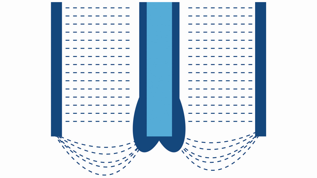
 Fig. 4: High current density zones vs. low current density zones vs. planting current thresholdAchievinga uniform surface can be a challenge, especially when coating complex shapes. For example, sharp edges attract more debris and can create the "dog bone" effect, where the thickness of the coating increases at these edges and ends. Similarly, areas closer to the anode are more likely to produce higher depositions, while areas further away (e.g. recessed areas) are more difficult to coat. The higher the fluctuation within the current ripple, the more pronounced this effect becomes (Fig. 3). The diagram in Figure 4 shows how the ripple effect affects the finishing of high current density zones (HCDZ) and low current density zones (LCDZ) when using an SCR - bearing in mind that even simple shaped parts have higher current density zones. If the variations in waviness are high, the deposition is not uniform, resulting in an inhomogeneous surface and low quality.
 Fig. 3: The higher the fluctuation within the current ripple, the more pronounced the dog-bone effect becomes
At current densities of less than 288 ASF (for hard chrome plating solutions at 130 °F or 54 °C , shown in purple), the chrome deposit becomes milky and dull. Each time the ripple falls below the minimum threshold, nothing is deposited. The average density is the current read on the ammeter divided by the total surface area of the part to be coated (shown in blue). The current flowing into the high current density zones (HCDZ) is shown by the blue line, and the lower current density zones (LCDZ) are shown in green. Within each phase of the ripple, both fall to zero so that the minimum threshold for the coating is not reached.
Ripple fluctuations influence processing quality
The diagram in Figure 5 now compares the unfiltered ripple of a 6-pulse SCR with the output of a switched-mode rectifier.
 Fig. 5: Failure time of power supply units with high ripple compared to those with low ripple
As we have already seen, the SCR power supply drops to zero at any ripple of 950+ ASF for both LCDZ and LHDZ. This shows that the coating process is constantly interrupted, the peaks consume too much material and energy and the troughs fall below the minimum threshold. In contrast, the switching rectifier achieves a constant value of 314-460 ASF. And unlike SCRs, the power supply never drops to zero.
Impact of better power supply and coating quality on production
By improving the power supply - reducing the ripple through a switching rectifier - the spreading capability is improved. The coating of zones with low current density will be around 15% thicker, which will speed up processes and reduce energy consumption accordingly. The time and labor required to grind high current density zones will be reduced as approximately 12.7% less material will need to be removed - a significant reduction in material waste while reducing labor costs and production time. This is particularly valuable when hard chrome plating on expensive automotive and aerospace components. Difficult and complex shapes can be coated more successfully and efficiently.
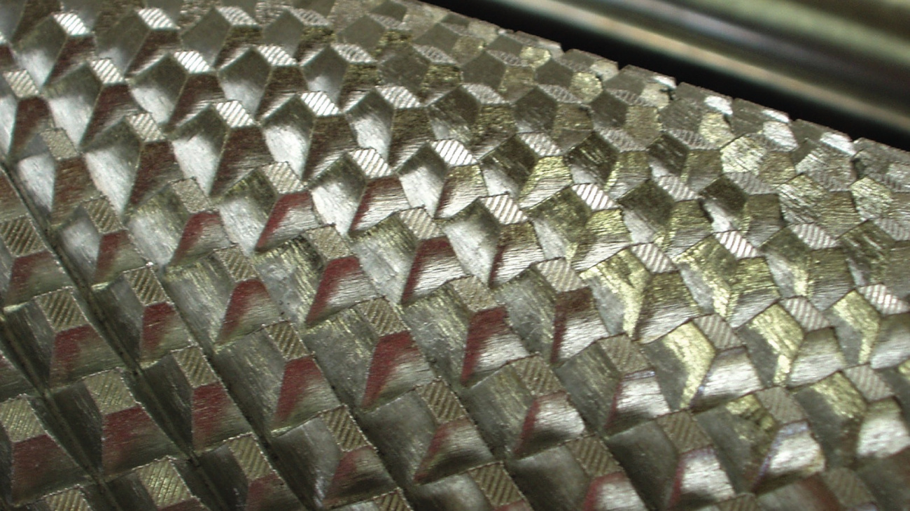
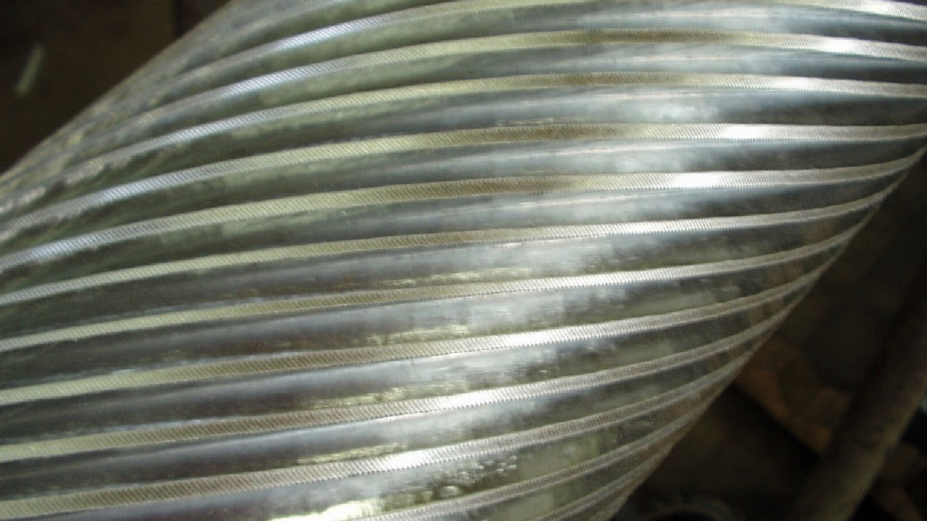
Fig. 6: Here the coating was applied using a Kraftpowercon switching rectifier. Only minimal rework was required
In the example in Figure 6, the use of a silicon-controlled rectifier meant that the central core area of the helix was not coated. After replacing this with a KraftPowercon switching rectifier, the entire component was successfully coated - only minimal rework was required to remove the burns on the outer areas.
If a batch can be coated with higher quality in less time with a switching rectifier than with a conventional rectifier, this inevitably leads to a reduction in working hours, energy costs and chemical consumption and optimizes your added value sustainably and reproducibly.
INFO
Kraftpowercon
Online energy-saving calculator for switching KraftPowercon FlexKraft rectifiers from thristor to switch-mode technology: calculator.kraftpowercon.com
