In the production of sensor elements, the necessary encapsulation can be carried out using a pressurized glass feedthrough. This process is currently carried out in a time-consuming oven process in which the entire component is heated to the melting temperature (> 400 °C) of the glass. If temperature-sensitive components are integrated in the sensor, the furnace process is not an option. For this reason, the Fraunhofer Institute for Laser Technology and IL Metronic Sensortechnik are investigating a laser-based process as part of a BMWi funding program.
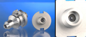 Fig. 1: Application example of a pressure glass feedthrough for a metallic conductor. The detailed view (right) shows the melted glass body that encloses the conductor helium-tightInthe manufacture of sensor elements, the necessary encapsulation can be achieved by a pressure glass feedthrough. This process is currently carried out in a time-consuming furnace process in which the entire component is heated to the melting temperature (> 400 °C) of the glass. If temperature-sensitive components are integrated in the sensor, the furnace process is not an option. For this reason, Fraunhofer Institute for Laser Technology and IL Metronic Sensortechnik are investigating a laser-based process as part of a BMWi funding program.
The demand for system-integrated sensors in various application areas has been growing steadily for years. This development is accompanied by an increasing complexity of electronic circuits and components. Assembly and connection technology is therefore facing new challenges, as encapsulation processes that are both efficient and gentle on the complex electronic systems are becoming necessary. For the technical realization of different sensor applications or sensor types, glass feedthroughs and, in particular, pressure glass feedthroughs are often used as an interface between the sensor unit and the sensor electronics.
This type of contact feedthrough can withstand high temperatures, pressures and aggressive media. Accordingly, pressure glass feedthroughs are often used for humidity, temperature, pressure, flow and vacuum sensors in order to ensure hermetic plating from the measuring medium to the evaluation electronics. For example, glass feedthroughs are used in pacemakers in medical technology. They enable electrical conduction from the battery to the residual electronics. In cooling technology, the glass feedthrough serves as an electrical bridge between the control unit and the cooling unit. In aviation, it enables the electrical control of kerosene injection in airplanes. Another application here is high-temperature sensors that can be used in engines to monitor combustion.
These pressure glass feedthroughs are currently manufactured in a time-consuming furnace process in which the glass body, including the socket and the electronic contacts, is heated to the melting temperature of the glass (see Fig. 1). The melting temperature of melt-in glass is typically above 400 °C. The hermetic connection is based on the one hand on the wetting capacity of the molten glass and on the other hand on the mechanism of thermal compression that occurs during the furnace cooling process due to the different coefficients of thermal expansion of the metallic frame and the glass. The furnace process is problematic as soon as electronic components are integrated whose temperature load must remain well below 400 °C. The connection for such sensors cannot be realized with an oven process. A process in which the temperature load on the electronic components remains below a destruction threshold is therefore required.
For this reason, the Fraunhofer Institute for Laser Technology and IL Metronic Sensortechnik have applied for an R&D cooperation project as part of the BMWi ZIM funding program. The aim of the cooperation project is to develop a laser-based process for the production of pressure glass feedthroughs for temperature-sensitive multilayer ceramics that would be destroyed by the thermal stress of a furnace process. In the first part of the project, which is presented here, the feasibility in principle was investigated using a given component and compared with results from a furnace-based process.
Laser radiation as a focusable heat source
In the laser-based process, the laser radiation from a diode laser (wavelength: 808 nm) is set in a rotational motion at a speed of 1000 mm/s with the aid of a scanner. The laser radiation moving on a circular path falls onto a copper funnel, whose highly reflective surface reflects the radiation towards the metallic holder.
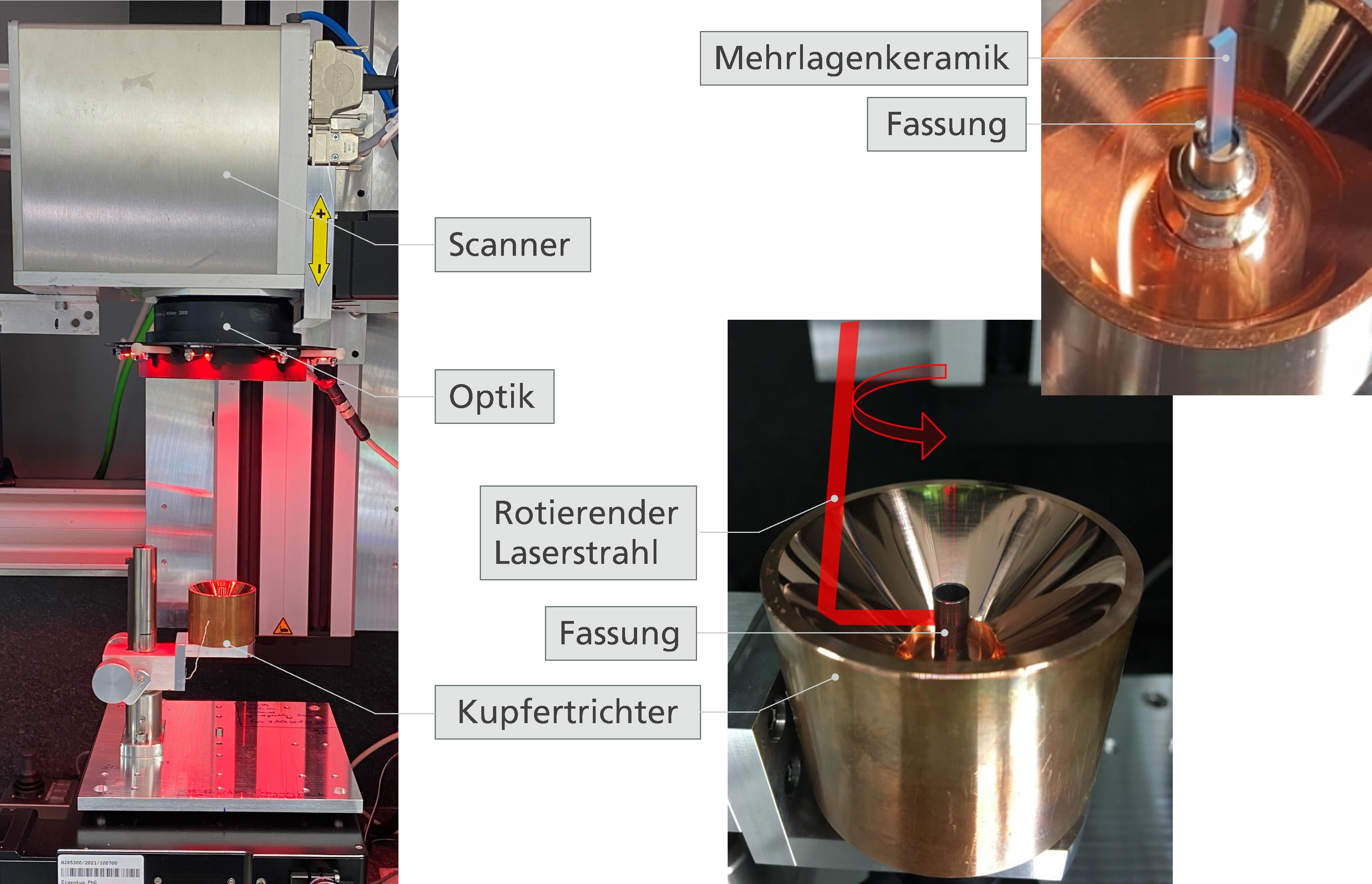 Fig. 2: Experimental setup for the laser-based production of pressure glass feedthroughs (general view on the left; detailed view on the right)
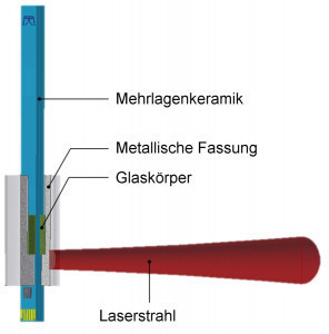 Fig. 3: Schematic representation of a metallic frame exposed to focused laser radiation, which encloses the glass body and the multilayer ceramic. The socket is heated locally by the focused laser beamThesocket is placed in the center of the copper funnel so that it is irradiated homogeneously all around. The multilayer ceramic is located inside the frame next to the glass body, which was previously pressed into shape and sintered (see Figs. 2 and 3). The radiation energy absorbed by the frame is converted into heat energy. This leads to a rapid rise in temperature in the setting. Part of the heat supplied flows into the glass body via heat conduction, causing it to melt and wet both the frame wall and the multilayer ceramic. A ceramic aperture with an opening the same size as the cross-section of the multilayer ceramic ensures that the molten sintered glass body remains in the frame and does not escape from the frame due to gravity. When the laser is switched off, the cooling of the component and thus the mechanism of thermal compression starts. With uniform wetting, a hermetic connection can then be created.
A key material property that determines the absorption of the laser radiation and therefore the heating is the reflectivity of the frame. The rule is: the lower the reflectivity values, the higher the absorption values. As studies have shown, the reflectivity of the frame can be influenced by an upstream furnace process. The reflection of the laser radiation is reduced by more than 20 % from 60.7 % to 39.3 % if the frame is kept in the oven for just 1 hour at a temperature of 500 °C. Figure 4 shows the influence of the reflectivity as a function of the dwell time of the mount in an oven process at 500 °C. The reflectance values recorded by the spectrometer fall with increasing dwell time in the measured wavelength range from 500 to 2000 nm.
With a 120-hour dwell time of the frame in the furnace, the reflection of the laser radiation is only reduced by a factor of 2.5 in absolute terms. As the radiation reflection could already be significantly reduced in the relevant wavelength range after a one-hour furnace process, the furnace process for the frames was placed upstream of the laser process in the test routine.
Thermal simulations for the laser process
The test series are supported by thermal simulations in order to determine the laser parameters at which the glass body melts. The parameters considered here are laser power and irradiation duration as well as the irradiation position of the laser beam on the metallic frame (see Fig. 3). The simulations were carried out using Comsol Multiphysics® simulation software. The simulations are based on a simplified model component, which includes the component(Fig. 3), the brackets and a copper block instead of the copper funnel(Fig. 2, right). For further simplification, it is assumed that the laser beam illuminates the entire surface it passes over during processing at the same time. This corresponds to a high circulation speed. The influence of the irradiation position on the temperature distribution is shown as an example. Figure 5 shows the distribution of the maximum temperature in a false color representation and the melting temperature isotherm.
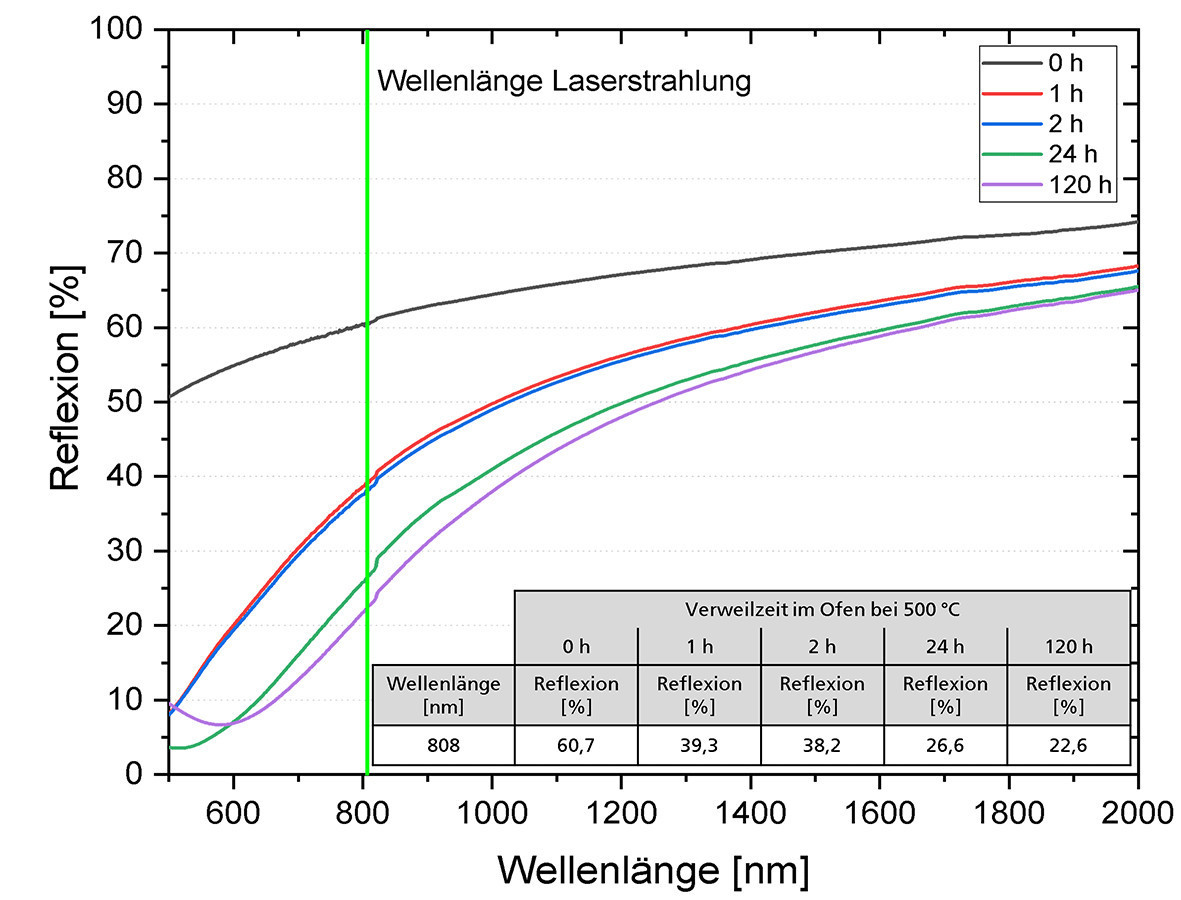 Fig. 4: Influence of the dwell time of Inconel flat samples in a furnace at 500 °C on the reflection of laser radiation for the wavelength range from 500 to 2000 nm
If the laser beam strikes well below the glass body(Fig. 5, left), the heat flow into the glass body is no longer sufficient to heat it to melting temperature (400 °C). If the beam strikes at the height of the glass body or above(Fig. 5, center, right), the glass body is heated to melting temperature. However, the temperature load of the frame also increases significantly with temperatures above 700 °C(Fig. 5, right).
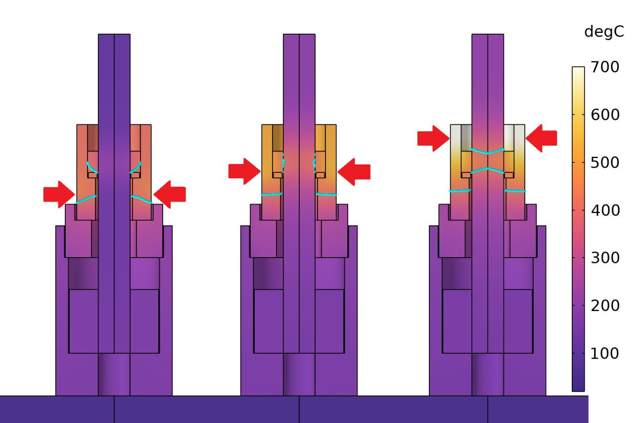 Fig. 5: Temperature distribution and melting isotherm (cyan) for different irradiation positions (arrows) in the cross-section, laser power = 85 W, irradiation time = 33 s, only a section of the copper block below is shown
Helium-tight joint
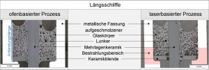 Fig. 6: Longitudinal sections of two pressure glass feedthroughs that were produced using furnace-based (left) and laser-based (right) methods. In the right-hand section, the area of the frame that was exposed to laser radiation is marked in colorFirstinvestigations have shown that helium-tight pressure glass feedthroughs can be produced using laser radiation. The leakage rates of the laser-based feedthroughs determined with a leakage tester are similar to the furnace-based feedthroughs in the range of 5x10⁻¹⁰ to 3x10⁻⁹ mbar*l/s. This leakage rate, as well as the proven helium tightness, meets the high demands of many applications, for example in the field of sensor technology.
A comparison of longitudinal sections of furnace- and laser-produced pressure glass feedthroughs shows slight differences in the appearance of the melted glass body, as shown in Figure 6. In both cases, the glass body wets the frame wall and the multilayer ceramic in the center of the frame. To produce these connections, two stacked glass bodies were fused together to increase the connection length.
To produce the furnace-based pressure glass feedthrough in Figure 6, the frame including the multilayer ceramic, the aperture and the glass body was subjected to a furnace process at a temperature of 480 °C for 50 minutes. Including the furnace heating and cooling time, the furnace-based process, which enables batch operation, takes around 3.5 hours. In contrast, the laser-based process required 105 seconds to produce the joint shown in Figure 6. Regardless of the heat source, the molten glass body is riddled with blowholes. While the number and size of the blowholes in the furnace-based compound are homogeneously distributed, the size distribution of the blowholes in the laser-melted glass body depends on the location. In the edge zone, in which the glass body is adjacent to the area covered by the laser radiation, the melted glass body has a collection of larger blowholes, as this is where the highest temperatures are achieved during the process.
Irrespective of the blowholes, a leakage rate in the range of 10-10 mbar*l/s is determined for the laser-produced joint by means of a leakage test. This is comparable to the leak rate determined for the oven-based version.
The number and size of blowholes have no influence on the tightness of the laser-based joint, as Figure 7 shows. This is the result of initial test series in which the influence of the selected laser power or energy input on the process was investigated. An energy input of 2923 J at a maximum laser power of 79 W (see Fig. 7 No. 1) does not ensure complete wetting of the frame wall and thus no "tight" joint, as the top view of the glass body and the longitudinal section show. Only when the energy input increases (see Fig. 7 No. 2 to 4) by increasing the laser power is complete wetting of the frame wall achieved. The longitudinal sections show a visible enlargement of the blowholes with increasing energy input. However, the determined leakage rates of the joints remain unaffected by the blowhole size in the range of 10-9 mbar*l/s. In comparison to Figure 6, only one glass body was melted in these tests. Accordingly, the bonding length between the melted glass body and the frame wall or multilayer ceramic is almost halved.
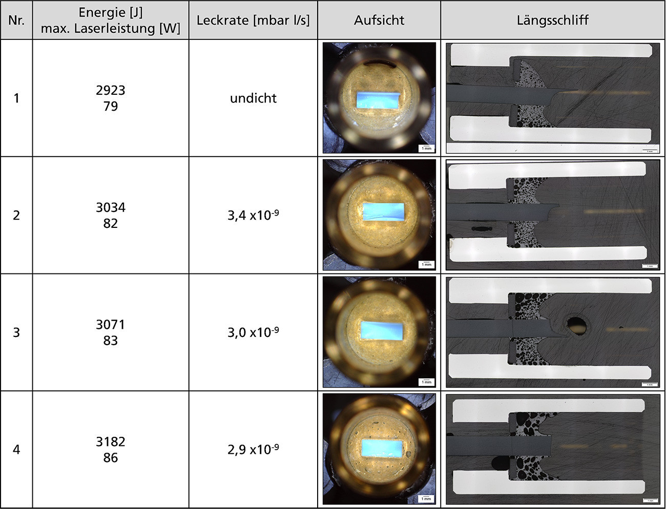 Fig. 7: Influence of the radiation energy by varying the maximum laser power on the melting behavior of the glass body and the leakage rate of the bond achieved
Note: The multilayer ceramic was removed on one side for an unrestricted view of the molten sintered glass body. Any cracks, visible in the longitudinal section, were caused by the mechanical stress during sample preparation.
The influence of the size of the blowholes on the strength of the connection, for example, and whether the connection length of the melted glass body to the frame wall and to the multilayer ceramic influences the determined leakage rate will be investigated in the further course of the cooperation project and, if necessary, described at a later date.
The cooperation project described is funded by the Federal Ministry for Economic Affairs and Energy on the basis of a resolution of the German Bundestag.


