In addition to the use of artificial intelligence (AI), the use of digital twins is no less important when it comes to efficiency - especially when it comes to AOI inspection systems.
In combination with the use of AOI systems, the technology of the 'digital twin' can be used in different ways. For example, a virtual offline programming station can be used to create a digital image of the AOI system used, which contains all the parameters from the real world.
Another very interesting area of application for the digital twin is the mapping of the electronic assembly, which is not yet physically present but is to be produced and tested shortly(Fig. 1). Well-prepared CAD data already provides a great deal of helpful information for creating an AOI test program; however, there are still a number of gaps for comprehensive parameterization.
The following article takes up these two use cases for the digital twin and explains their advantages and possibilities in more detail.
Digital image of the assembly as a first step
Particularly in the case of electronic assemblies that are only produced in small quantities, rapid test program creation and minimal debugging effort are extremely important. The information available for this is generally based on production data. Commonly used here are center point coordinates of the components and Gerber data for the layout of the PCB. It is often somewhat more difficult when manufacturing service providers want to access ODB++ data, which typically contains further information for AOI program creation. However, crucial specifications for AOI test functions are not available with this format either. This applies, for example, to information on the geometry of the component connections and their contact surfaces on the pads. Unfortunately, dimensional data on the component height or the expansion of the body is also not available with this database.
This means that extensive design libraries must be used for the parameterization of AOI test programs. The result is the often very time-consuming creation and maintenance of an AOI library including an article number reference. However, there are two ways around this: The first way is to create a library and the associated reference table for article numbers fully automatically using the data mentioned at the beginning, including an existing sample assembly. All parameters required in addition to the imported data are determined directly from the assembly in a first run and an AOI library based on article numbers is created fully automatically. This option is provided by the 'PILOT AOI' system software from GOEPEL electronic with the powerful 'MagicClick' function. The digital image of the assembly is thus generated from the real object in the first step and the AOI test program including library is then created fully automatically(Fig. 2).
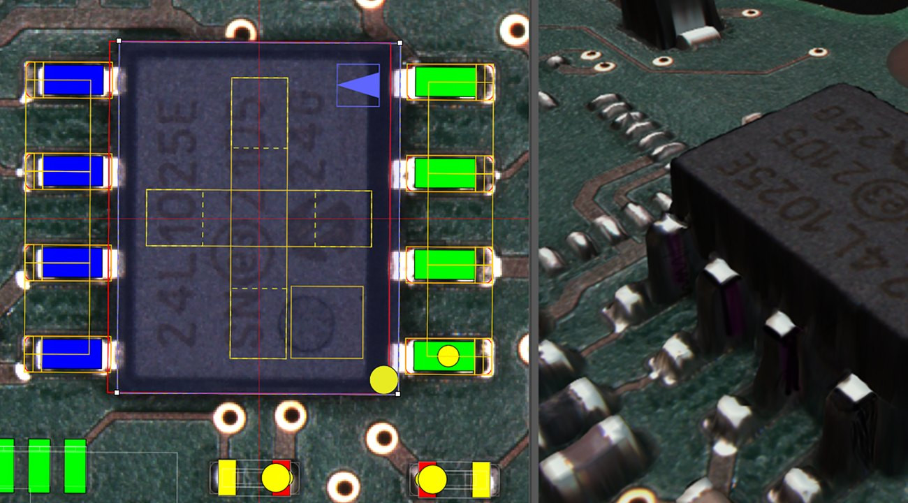 Fig. 2: 'PILOT AOI' in use; Image: GOEPEL electronicIn order tobe able to take this step before the first assembly is manufactured, it is essential to provide detailed geometry data of the PCB and components. The ODB++Process data format offers one possibility for this. All AOI-relevant data (e.g. the pin shape and its contact surfaces on the pad) are generated using the manufacturer's design data with reference to the part number of the respective component and are available for creating the test program. PILOT AOI' offers such a data import and thus enables a much faster and more precise parameter specification for the respective AOI program.
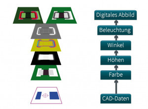
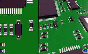
However, the characteristics of the solder joints, taking into account the production parameters as well as the camera configuration and the lighting arrangement in the AOI system, are still not taken into account. In order to reproduce these, a simulation process in several steps is necessary. The sequence of this process is shown in Figure 3, the result of which is the digital image of the assembly(Fig. 4).
Digital twin of the AOI system
However, the technology of the digital twin offers a further, very efficient application option with regard to the manufacturing process: the AOI system itself. It typically has a long life in the production line and is supplied by the manufacturer with updates and upgrades in both the hardware and software areas. Training, support and further development of the software generally accompany the real AOI system throughout its entire life cycle.
A digital twin of the complete AOI system is the ideal concept for supporting these requirements, implementing them to a high standard and, above all, accelerating them. For this reason, various familiar and new tools are combined to create a digital image of the system and its behavior. This digital twin is intended to virtualize and simulate as many requirements, processes and behaviours as possible, both for the user and for GOEPEL electronic. The basic aim of this virtual representation of the AOI system is to improve the efficiency, performance and reliability of its physical counterpart.
This is realized by a single exchangeable file that contains as much detailed information as possible about an AOI system: Axis parameters, camera configuration, measuring head type and its parameters, lighting situations and many other software and hardware parameters. The hardware environment, i.e. the real AOI system itself, is abstracted and simulated based on concepts familiar from information and computer technology such as 'virtual machine', 'image' and 'sandbox'. The resulting image can be distributed and reloaded as required. In conjunction with a virtual assembly including simulated solder joints, a flexibly usable virtual data space is created.
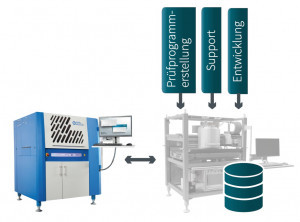 Fig. 5: Digital image of the AOI system Image: GOEPEL electronicTheuser can thus carry out the test program creation cost-efficiently without having to rely on an actual system or a real assembly. This can be done away from the production line on a desktop PC or notebook. Potential challenges with the PCB layout or test depth can be overcome at an early stage. Training, further training or special tests can be carried out at an early stage without putting a strain on the real system in terms of time. All system types available to the user from the SPI and AOI portfolio can be loaded within 'PILOT AOI' with a single click in order to test the test program under various conditions(Fig. 5).
At GOEPEL electronic's headquarters, the actual digital twin of the customer system offers an immense advantage in terms of service and support. The virtual system including measurement data of an inspected assembly can be made available in-house for programming support and troubleshooting in the shortest possible time. This enables a more precise and faster analysis and investigation. The user's request, including the digital image of the system and the assembly, can be passed on to 2nd level support and development. The real system in the production line, decoupled from this process, is already available for processing the next orders. This quickly eliminates the need for remote support or service work on the AOI system, which is time-consuming for the user in terms of planning.
The digital twin - an adaptive system
The advantages of the virtual AOI system have also become apparent in the development process of the 'PILOT AOI' system software. New features are developed and tested in the virtual environment of its real counterpart right from the start. This means that development is as close as possible to the physically real world right from the start. During software testing on the real system, nasty surprises are reduced to a minimum, resulting in further cost and time savings during development.
It turns out that the digital twin offers an adaptive model that can be used for a wide variety of perspectives and viewing areas; on the one hand for the manufacturer in the development, production and maintenance of partial or complete systems that influence their product or represent their product itself, and on the other hand for the user, who can in turn integrate the digital twin of the product into their virtual overall system. Overall, this technology results in a high efficiency gain, especially for AOI use, in an extremely resource-efficient manner.
About the authors
Dipl.-Ing. Jens Kokott studied instrument and precision engineering at the Friedrich Schiller University in Jena and business administration at the University of Hagen. From 1991 to 1992, he was a research assistant at the University of Jena. Jens Kokott joined GOEPEL electronic in 1992 to set up the automatic inspection division. He has been Product Manager for AOI systems since 2016.
Dipl.-Ing. (FH) Frank Hauswald studied communication and media technology at the University of Applied Sciences in Jena and completed his studies with his diploma thesis on character recognition on electronic components at GOEPEL electronic. He has been working there since 2010 as a software developer for the 'PILOT AOI' system software in the field of automatic inspection.


