
The technical article is based on an article by Elisa Pouyanne, Market Development Manager at Siemens Digital Industries Software IES. The development of modern vehicles is confronted with increasingly complex electrical and electronic systems. The growing scope of data networking significantly increases costs, primarily due to the additional components and their arrangement in the vehicle and their wiring (harness).
This growing complexity also causes considerable problems during revisions and redesigns. This is because new routings and circuit layouts have to be taken into account, which increases the likelihood of errors.
Errors in electrical systems or wiring harnesses can lead to incorrect functionality or even danger for customers when they are later used in the vehicle. The closest possible integration of design software in the form of ECAD (Electronic CAD) and MCAD (Mechanical CAD) is therefore becoming increasingly critical, as modern vehicles are both electronic and electromechanical products. As technology advances, so do the requirements for their increasingly complex electrical and mechanical design. This complexity is a growing challenge for the design teams involved. When electromechanical aspects are involved, as is the case with a wiring harness, the mechanical and electrical developers must consider the respective requirements and challenges across departments and solve them together.
For example, the mechanical developers must verify the spatial restrictions for wiring harnesses imposed by the vehicle layout, which are given by the diameter of the cable bundles and thus determine their final content(Fig. 1). Accordingly, electrical designers must take into account conductor lengths to analyze voltage drops and fuse sizing to ensure the correct behavior of their circuits. And the harness designer must reproduce the 3D harness topology as a 2D equivalent and relate this to the associated electrical data. If the 2D harness is a derivative of the 3D harness, why develop it from scratch?
Modern tools for current challenges
To solve these challenges, new E/E systems and wiring tools are constantly emerging to facilitate collaboration, reduce design costs and risks, and shorten development cycles. A design flow with modern tools, such as VeSys from Siemens Digital Industries Software, supports collaboration with parallel development of the electrical and mechanical domains(Fig. 2). The mechanical developer defines the geometry of the wiring harness and its accessories, taking into account the space available in the vehicle or machine. On the other hand, the electrical designer deals with the electronic content of the system, creates the required circuit diagrams and carries out the corresponding analyses. Although the mechanical and electrical areas work independently of each other, they exchange all available data in a simple manner. The wire harness designer then combines the MCAD and electrical data to define the electromechanical product wire harness.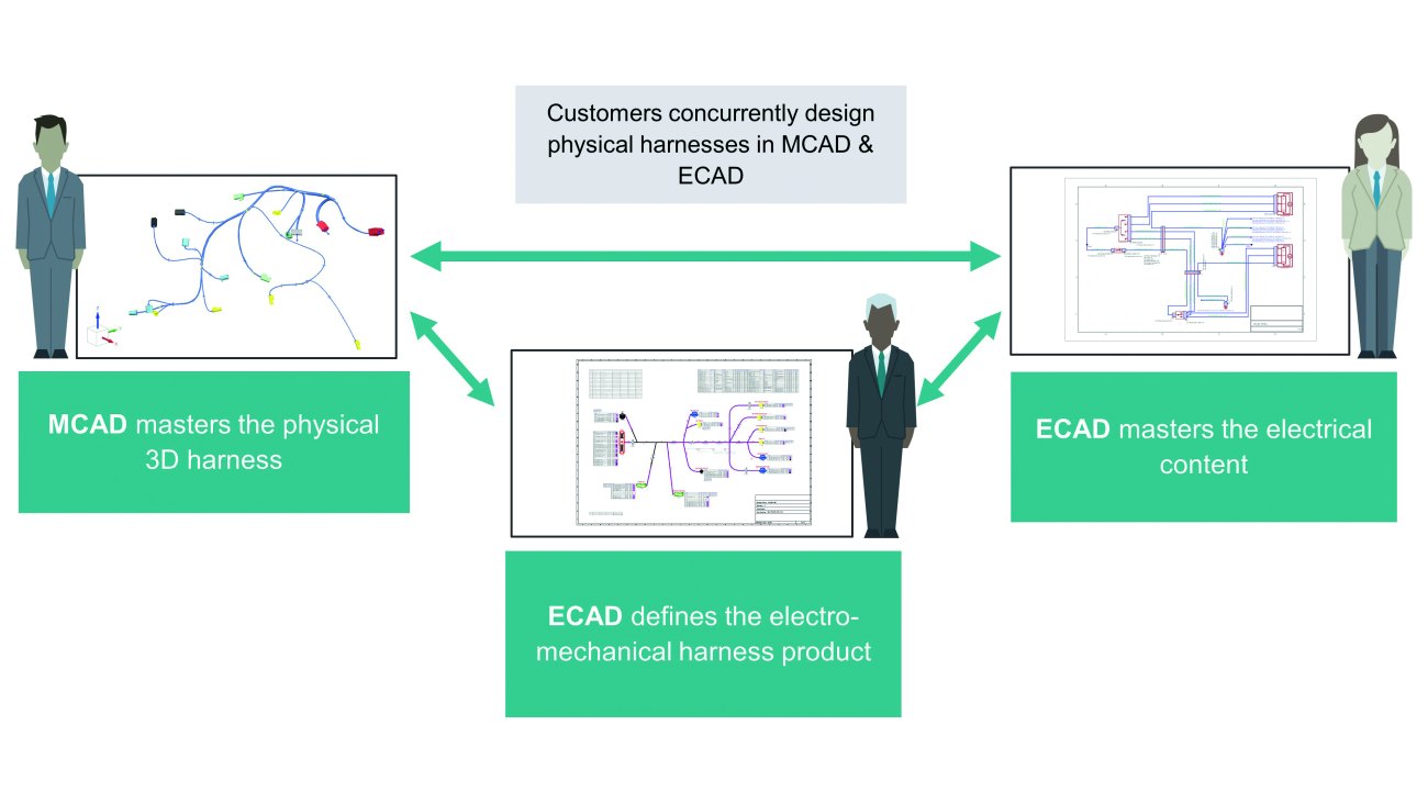 Fig. 2: Digitalization enables the close integration of the electrical and mechanical domains for a better overview of the development process
These interactions increase the visibility between the ECAD and MCAD domains. This supports the co-design of mechatronic or electromechanical products. Ultimately, this interaction promotes a better understanding of the specific electrical and mechanical decisions in the other domain - and this improves the overall design quality. In addition, data exchange through modern tools eliminates the need for manual data transfers between the two environments. This saves development time and reduces the potential for manually induced errors.
Direct connections avoid domain silos
This robust ability to integrate domains is achieved through two key features. Firstly, a framework of cross-domain bridges and adapters handles the exchange of information between the MCAD tools and the electrical development environment. Secondly, APIs from each MCAD application are used to develop plug-ins that are used in the MCAD-optimized products. Plug-ins ensure the seamless integration of data between the tools. For example, VeSys supports integration with PTC-CREO, Siemens NX and Solid Edge software as well as SolidWorks and CATIA V5 from Dassault Systémes.
The NX and Solid Edge software enables intensive data exchange with real-time import and export, as well as cross-highlighting for simplified analysis when developing the system wiring and cable harness. This functionality automatically switches between wiring and harness mode as required within an application. This means that all selected objects in the MCAD solution are also marked in the electrical circuit diagram, and vice versa. Thus, the selection of a wire in the electrical solution also marks its shortest possible routing and the components to which the wire connects in the mechanical environment.
A detailed example
In this example, we focus on the exchange of data between electrical and mechanical developers. The wiring information for the electrical system and the wiring harness appears in the mechanical domain in the form of a Wiring PLM XML file. Once the data has been exported to the MCAD tool, the appropriate connectors are automatically assigned. The routing of the wiring is also carried out automatically.
Initially, the MCAD design does not contain any electrical information, only the cable bundles and connectors added by the mechanical designer. A direct connection between the tools can be established at the touch of a button. This allows data to be imported and exported in real time. In this case, the mechanical design receives the electrical data as a PLM XML file of the wiring. A built-in filter mechanism allows the user to select and exchange specific harness designs. For example, the electrical developer selects the design of the driver's side door and exports the electrical data to the mechanical tool. An overview lists the number of connectors, splices and wires that have been taken into account.
The MCAD tool is then populated with the electrical data(Fig. 3). This allows the mechanical designer to automatically assign the required connectors and all other remaining components and elements, such as the splices. The connectors can be arranged automatically by component number or any other feature of the component. The mechanical designer can then carry out the automatic routing of the wires at component level(Fig. 4). The automated data transport between the design tools has provided the mechanical designer with all the data to assign part numbers for connectors and determine the routing of the wires. As a result, the mechanical designer was able to quickly and accurately recreate the connectivity from the schematic diagram. This saves considerable time compared to manual, error-prone processes.
 Fig. 3: The electrical developer exports the wiring data to the MCAD environment
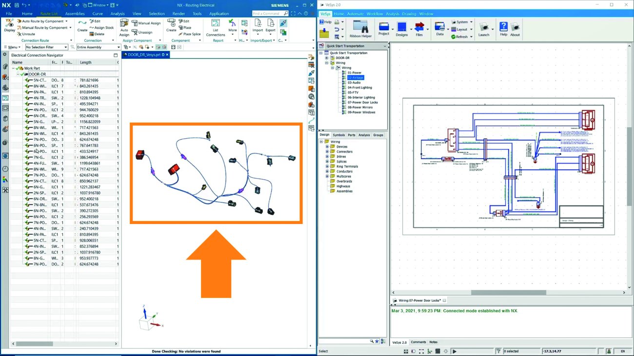 Fig. 4: The mechanical developer uses the electrical data to carry out the automatic routing of the wiring at component level
After the mechanical designer has completed the routing of the wiring in the wiring harness of the driver's door, it is updated with the exact length according to the space conditions in the three-dimensional physical design space. This is important information that the electrical developer can use to perform further circuit analysis and verify the behavior of the electrical system. In this case, we transfer the data from the mechanical solution back to the electrical domain.
With the ECAD and MCAD tools already networked, the electrical developer only has to import the required data from the mechanical environment. As with the previous export, an overview report is provided that describes the data transferred back to the electrical domain. All wires in the ECAD solution are now updated with their correct length from the mechanical design. This allows the electrical designer to more accurately analyze the voltage drops and dimension the fuses.
The power of electrical-mechanical integration
The transformation of companies towards end-to-end digitalization is increasingly proving to be a critical factor as products and processes in all industrial sectors become more complex. Connected digital tools, such as VeSys from the Xcelerator portfolio, are enabling manufacturers to develop next-generation products in increasingly demanding environments. ECAD/MCAD integration in particular supports the development of mechatronic products with increasing demand and complexity. Improved visibility between domains is particularly important for cross-functional design teams to maximize efficiency. Similarly, increasing automation in design and data exchange allows developers more time to focus on design validation and innovation. Both improve design quality. As the electrical and mechanical areas of design are of equal importance, this ultimately results in much better products.
