The model presented can be used to calculate rinsing cascades, whereby immersion and spray rinsing can also be represented for non-ideal rinsing. The flexible model can also be used to calculate circuit rinsing, recirculation rinsing and spray chamber rinsing.
1 Introduction
A model for calculating the steady-state conditions in rinsing cascades is presented. It can be used to calculate important effects in rinsing practice such as incomplete mixing and spray rinsing. By extending the previously developed matrix model, additional variants of water feed and spray rinsing can be represented. Furthermore, it is shown how ion exchange circuit rinsing, recirculation rinsing and spray chamber rinsing can be calculated by selecting suitable parameters. The final examples demonstrate the flexibility of calculating very different rinsing processes.
1.1 Importance of rinsing
The aim of electroplating is to specifically change certain surface properties of the treated product. The main processes, in which the surface is coated with metal, material is removed from the surface or chemical transformation processes take place on the surface, serve this purpose. The main processes are preceded by pre-treatment steps to degrease, remove dirt, oxide and hydroxide layers and activate the surface. All these process steps are carried out in process solutions containing specific substances. These substances cause chemical, electrochemical and physicochemical processes at the interface between the product and the process solution.
In the vast majority of cases, the individual treatment steps must be decoupled from each other, as the substances in one step usually have negative effects in the following step. Decoupling is achieved by rinsing the product. Rinsing takes place with water and is based on the dilution of the liquid film on the surface of the fabric. After rinsing, the fabric reaches the next treatment step with a liquid film that only contains the process solution from the last treatment step in a highly diluted form. Rinsing only takes place in the final rinse with the aim of ensuring that the product leaves the treatment line free of residue. The final rinse makes a direct contribution to quality by ensuring that no residues are left behind. The intermediate rinses contribute indirectly to quality, as insufficient decoupling of the individual process stages leads to quality problems during surface treatment.
Rinsing processes can be found in large numbers in electroplating and wet-chemical surface treatment lines and consume different resources. Rinsing processes mean investments in plant engineering. In particular, they require production space. For example, production lines for surface treatment often consist of more than 50 % rinsing. During operation, water and energy (circulation, pumps) are required for rinsing. Rinsing also generates waste water and is therefore also relevant for chemical and energy consumption in waste water treatment.
1.2 Design of flushing systems
The design of flushing processes is multifaceted. Different rinsing technologies are available. The product can be immersed in rinsing solution or sprayed with rinsing solution. Immersion and spray rinsing are often combined. Rinsing systems usually consist of a sequence of rinsing steps, known as rinsing cascades. There are also various options for operating rinsing processes. In continuous mode, the rinsing water flows continuously. In contrast, in discontinuous operation (batch mode), the rinsing water is exchanged at intervals. It is not uncommon for mixed regimes to be implemented.
In systems for treating rack or drum goods, rinsing systems are usually designed as a sequence of several rinsing stages (rinsing cascade). In each of the rinsing steps, the liquid film carried over on the surface is diluted. To save water, the rinsing cascade is operated in counterflow. The fabric runs from the first to the last rinsing stage, while the rinsing water flows from the last to the first stage in counterflow. Special structures are created when concentrators (ion exchangers, evaporators, reverse osmosis systems) are included in the rinsing system.
Rinsing systems are specified as follows:
1. structure of the rinsing system
- Number of rinsing stages
- Per rinsing stage - Form of rinsing
- Immersion rinsing
- Spray rinsing
- Immersion and spray rinsing combined
- Water supply
- Feed
- Connection between the stages
- Start-up sequence: If necessary, a different start-up sequence is defined for the rinsing stages, e.g. when implementing pre-dipping steps.
2. operating parameters of the flushing system
- Quantity of water supply
- Direct feed
- If necessary, supply via spray rinsing
- Times of the flushing step
- Rinsing time (dwell time)
- Draining time
- transport times
- Further parameters
- Set temperature for heated rinsing
- Form and intensity of mixing (circulation, air injection)
1.3 Calculation of rinsing systems
Rinsing systems must be designed in such a way that rinsing takes place with good quality. This means that the entrained solution must be sufficiently diluted. This quality requirement should be achieved while conserving resources. A mathematical calculation of the flushing processes is essential in order to be able to carry out a qualified design.
At first glance, the calculation of rinsing systems seems straightforward, as rinsing is purely a dilution process and chemical reactions hardly take place. Nevertheless, the calculation of practically used rinsing systems is often complex. For example, there is a structural diversity of rinsing processes. In addition, certain operating parameters are often not precisely known in practice. The parameters for spray rinsing processes and for non-ideal rinsing are usually not available at all or only inaccurately. Once all the necessary parameters have been compiled and the model equations formulated, it often becomes apparent that a simple arithmetic calculation of the required variables is not possible.
If changes over time are to be represented, dynamic models are required. These are based on differential equations (DGL). To represent time processes in flushing systems, the corresponding differential equation systems must be solved. In flushing systems, the time processes are relevant if, for example, it is necessary to answer the question of how quickly a concentration limit is reached. The service life of the rinse results accordingly.
Purely stationary calculations (i.e. without representing changes over time) are often sufficient for the design of flushing systems. This applies in particular to continuous operation of the flushing system. This also includes goods-cycled operation, in which rinsing water is fed or transported in the cycle of each goods carrier. If the operating parameters of a warewashing system do not fluctuate too much, stationary calculations provide good mean values for the calculated variables.
Another distinguishing feature of flushing models is the representation of the local distribution of process variables. This allows the spatial distribution of substance concentrations within the sink or on the fabric to be described. For the corresponding models, the mass transport in the washing cell must be represented with partial differential equations. The resulting system of partial differential equations can be resolved with numerical tools according to the local dimensions and time. The formation and solution of these models are extremely complex. Therefore-and since the local distribution is usually not essential for answering practical questions in the design and layout of flushing processes-local distributions of flushing processes are rarely calculated. Instead, a uniform concentration is assumed within a flushing tank. In systems theory, this is referred to as models with "concentrated parameters".
The specialist literature is dominated by highly simplified models of flushing processes. Models for stationary states of flushing systems are the most common. Practically relevant effects such as non-ideal rinsing or spray rinsing are usually not taken into account. In some cases, additional simplifications of model equations are carried out to make them easier to solve. A collection of corresponding calculation equations can be found in [1], for example. In earlier years, there were extensive publications on the subject of flushing, for example [2-6]. In recent years, less has been published, although the topic has not lost its topicality. Many existing flushing systems have potential for optimization. In addition, a qualified design of rinsing systems is necessary when designing any new electroplating system. An example of a more recent publication is [7]. Although the necessity of calculating purging systems is emphasized there, hardly any calculation approaches are provided.
If flushing systems are to be calculated, suitable calculation tools are required. In the simplest case, a pocket calculator will do. Spreadsheets (e.g. Microsoft Excel), mathematics software and specially developed calculation programs are also used. Only a few specially tailored software programs exist for calculating flushing processes. For the MATLAB/Simulink mathematics and simulation software, the "ECE Toolbox" [8] has been developed as a tool that can also be used flexibly to simulate flushing systems. Calculation tools on the Internet can be helpful for users who only need to carry out calculations of flushing systems occasionally. As part of a research project [9], a tool was developed for the web-based calculation of flushing processes [10], which was available on the Internet for around 10 years. Currently available is a tool from the US Surface Technology Environmental Resource Center (STERC), namely the "Rinse Systems Calculator" [11]. This tool, which is freely available on the Internet, can be used to calculate simple rinsing cascades (up to 4-stage) with and without a recirculation rinse.
1.4 Classification of the presented flushing model
In this paper, an extended model for calculating flushing systems is presented and it is shown how an extended application is possible. The basis of the extended model is a matrix model for calculating stationary conditions in flushing cascades, which was first presented in [12] and further developed in [13]. The model allows the effects of incomplete mixing, spray rinsing and, if necessary, pre-dipping steps to be taken into account.
The model presented here overcomes various limitations of the previous model. So far, only a water feed into the last sink could be calculated. It is not possible to feed water into the front steps in any other way. Furthermore, the representation of spray sinks previously only took into account a feed from the following flushing stage. Up to now, it was not possible to calculate spray rinsing with fresh water via the front stages. The model now presented makes this possible.
In addition to the structural extension, this publication shows possibilities for extended use of the model. For example, it describes how ion exchange circuit rinsing can be calculated simply by selecting suitable parameters. It is also shown how recirculation rinses with different water feed variants can be represented. The third additional application is spray chamber rinsing, i.e. empty rinsing tanks in which the product is sprayed.
Sections 2 and 3 of this paper derive the extended matrix model. Section 4 shows in general how the model can be used to calculate rinse concentrations and water requirements. Section 5 presents the extended uses of the model. The application of the matrix model is explained in section 6 using a series of practical examples.
2 General model 2.1 Flushing stage
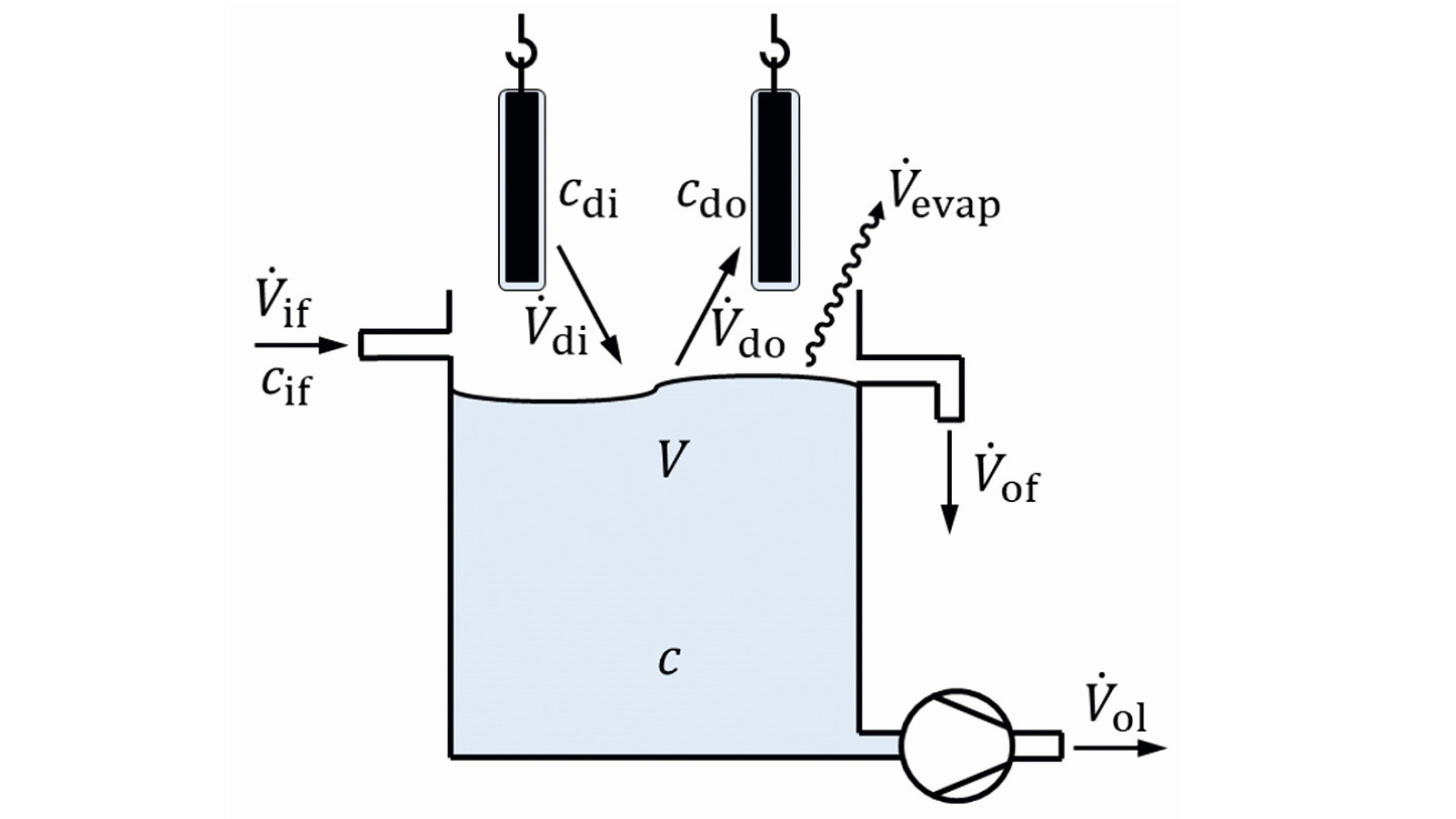
To form the model of a multi-stage flushing cascade, a single flushing stage is assumed. As shown in Figure 1, this is a container filled with rinsing water. Goods are immersed in this. Liquid from the previous step is carried away on the surface of the product. When the product leaves the sink, it carries liquid away again. Liquid can also be fed into the rinsing step or flow out of the step. A distinction must be made between overflow and drainage. Excess rinsing solution flows out automatically via the overflow when the corresponding fill level is reached. The same behavior occurs with continuous fill level control. The drain, on the other hand, describes a controlled volume removal, e.g. by a pump or a drain valve. Evaporation from the flushing stage can also occur. As a rule, this is purely the evaporation of water, i.e. substances contained in the rinsing solution do not evaporate.
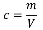
For mathematical modeling, the volume of the rinsing solution and the substances contained in the liquid are represented. If the mass of a substance contained in the volume of the rinsing liquid is considered, the corresponding substance concentration is obtained:
<1>
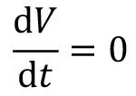
If no chemical reactions take place in the sink, but only dilution processes, it is sufficient to consider a single substance to describe the rinsing processes. If this representative substance changes its concentration, the concentrations of all other substances change proportionally. As the stationary flow behavior of a flushing cascade is to be modelled here, it is assumed that the flushing stage is always completely filled. There is no change in volume in the flushing tank:
<2>
The volume flows in Figure 1 can therefore be balanced using a simple algebraic equation:
<3>
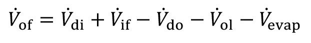
The overflow volume flow V.of, results here from the entrainment V.di, the entrainment V.do, the inflow V.if, the outflow V.o1,and the evaporation V.evap.
The basis for the description of the material changes in the "flushing stage" balance area is a mass balance of the dissolved substance:
<4>
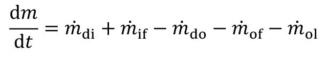
The above-mentioned volume flows (with the exception of evaporation) lead to a change in the mass of the substance under consideration and thus to a change in concentration.
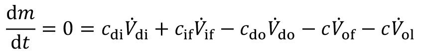
The stationary operating case is now to be described. This means that when operating with constant parameters, a constant concentration is achieved after a certain time. This means that the mass change on the left-hand side of equation <4> is zero. The individual mass flows result from the respective concentration and the associated volume flow:
<5>
2.2 Flushing cascade
The model of a single flushing stage described above now serves as the basis for the representation of a flushing cascade. Figure 2 shows the diagram of a general n-stage cascade flush. It can be seen that there is a carryover from the treatment process to the first rinsing stage, from there to the second stage and so on to the last rinsing stage. In the counterflow, rinse water flows from the last rinse stage to the penultimate stage and so on to the first rinse stage. In addition, as described above, there can be outflowing volume flows and evaporation in all flushing stages.
 Fig. 2: Counterflow flushing cascade
For this flushing structure, the volume flow equation <3> can be used for each individual stage. The coupling via carryover and counterflow is taken into account accordingly:
<6>
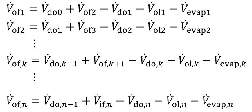
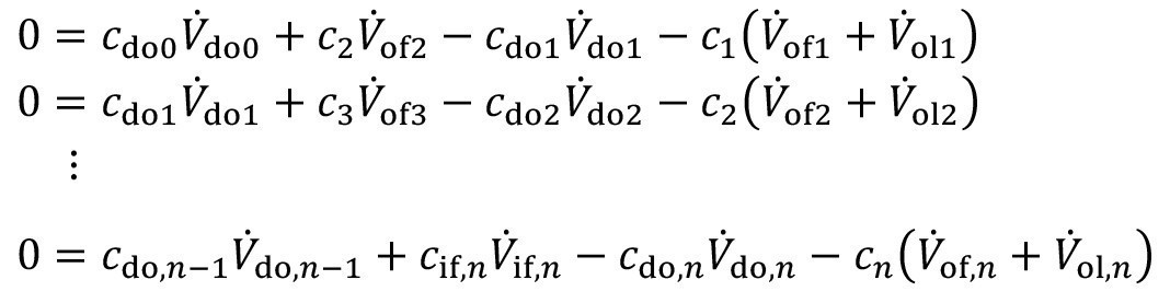
Similarly, the mass flow equation <5> can also be applied for each individual stage. Here too, the coupling via entrainment and countercurrent is taken into account accordingly:
<7>
2.3 Special flushing effects Pre-immersion
The model can be extended to represent special structures and effects. For example, a pre-dipping step can be easily mapped. In this case, the product is first transported from an upstream sink to the first rinsing stage and from there to the treatment process, see Fig. 3. After treatment, the usual rinsing sequence from the treatment process to sink 1, from there to sink 2 and so on.
 Fig. 3: Rinsing cascade with pre-soaking
The stationary rinsing model is adapted by modifying the volume flow equation and the mass flow equation for the first stage:
<8>

<9>

Here, V.do-1 describes the volume flow of the carryover from the upstream flushing stage. If the substance under consideration is already contained there, this is quantified with the concentration c-1. After pre-dipping, there is the additional carryover Vdo10, with the concentration cdo10.
Incomplete mixing
A practically significant effect in cascade rinsing is the fact that the liquid film on the product after removal from the rinsing stage generally does not have the concentration of the rinsing stage. Many simple models in the literature, however, assume that the concentration of the carryover is equal to the concentration in the rinsing stage (ideal mixing). However, this assumption does not apply for short flushing times, especially at low concentrations. A description of the effects of incomplete mixing proposed by Buczko [14] uses a factor of incomplete mixing α:
<10>
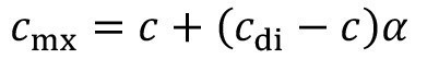
The incomplete mixing factor ranges from zero to one. For ideal mixing, it has the value zero; the concentration after immersion rinsingcmx is then equal to the concentration in rinsing stage c. If, however, the incomplete mixing factor is greater than zero, the concentration on the productcmx assumes a value between the entrainment concentration cdi and the rinsing concentration c.
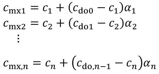
Equation (10) can be applied to the cascade accordingly:
<11>
Incomplete mixing rarely occurs in the treatment process, as the product usually remains there for much longer. If the effect must also be taken into account there in individual cases, this is done by analogy:
<12>
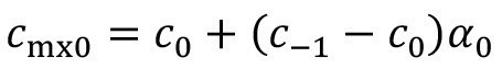
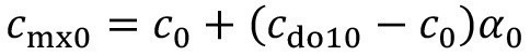
In the case of pre-dipping, the carryover concentration after the pre-dipping step with incomplete mixing is calculated using
<13>

Then, instead of equation <12>, the carryover from the process solution applies:
<14>
Equations <12> and <14> can be combined for generally valid modeling:
<15>

where the structural parameter ε is used to differentiate between the two cases:
<16>
Spray rinsing
 Fig. 4: Rinsing stage with combined immersion and spray rinsing
A frequently used technique to improve the rinsing quality is to spray the fabric as it leaves the rinsing stage. An immersion rinsing step is therefore combined with subsequent spray rinsing. Figure 4 shows the diagram of such a rinsing stage with combined immersion and spray rinsing.
The carryover concentration after spray rinsing cdo is set between the spray rinsing concentration csr and the concentration during excavationcmx. A corresponding factor ß was proposed in [15] to describe the effectiveness of pre-dipping:
<17>
The spray rinsing factor lies between the two limiting cases of ineffective spray rinsing (ß = 0) and ideal spray rinsing (ß = 1).
If each rinsing stage in a rinsing cascade is sprayed with rinsing water from the following stage, the corresponding equation can be applied to all stages as follows:
<18>
Figure 5 shows a corresponding cascade structure in which the spray rinsing is always carried out with rinsing water from the following rinsing stage. In the practical implementation of a corresponding spray rinsing cascade, the excess volume (or at least part of it) from the subsequent stage is used to spray the product. If not all of the surplus is required for spraying, the remaining part is fed directly into the corresponding stage parallel to spraying.
Literature
[1] Unruh, J.: Capable rinsing processes - rinsing quality according to ISO 9000. mo 50 (1996) 6, 462-469
[2] Clarke, M.: Rinsing: Part I - Theory of Recirculation and Chemical Rinsing. Transactions of the Institute of Metal Finishing 46 (1968) 201-208
[3] Kushner, J.; Kushner, A.: Water and Waste Control for the Plating Shop. Cincinnati, Gardner 2nd ed. 1981 [4] Winkler, L.: Rinsing - Quality Assurance and Environmental Protection - Parts 1 to 10. Galvanotechnik 85 (1994) 9 to 86 (1995) 12
[5] Kubík, C.: Rinsing - Theoretical principles and calculations of rinsing systems - Parts I to X. Electroplating 88 (1997) 11 to 92 (2001) 4
[6] Fischwasser, K.; Schwarz, R.; Süß, M.: Stoffverlustminimierte Prozesstechnik - Wann lohnen sich Regeneratoren und Konzentratoren? Chemie Ingenieur Technik 75 (2003) 6, 781-786
[7] Erlacher, N.; Hauser, H.: Rinsing is calculable and controllable - Parts 1-3. Galvanotechnik 104 (2013) 2-4, 333-336 / 554-557 / 777-778
[8] Giebler, E.: Simulation von Verfahrensprozessen - Bibliothek von Simulationsmodellen für galvano- und oberflächentechnische Verfahrensprozesse. Metal Surface 57 (2003) 1/2, 21-26
[9] AiF project no. 14189 N "Modeling and simulation of processes in electroplating and surface technology", Dresden University of Technology 2005-2007
[10] Reich, A.; Giebler, E.: Internet platform for the simulation of electroplating and surface technology processes. Oberflächentage 2006, Bonn
[11] Surface Technology Environmental Resource Center (STERC): Rinse Systems Calculator. www.sterc.org/subs/rinsecal.php (accessed August 2021)
[12] Giebler, E.: A General Steady State Model of Cascade Rinsing Systems. Transactions of the Institute of Metal Finishing 82 (2004) 3/4, 75-82
[13] Giebler, E.; Röbenack, K.: Flexible design calculations for rinsing cascades - Part 1/2. Galvanotechnik 98 (2007) 2/3, 474-480 / 753-759
[14] Buczko, Z.: Multistage Rinsing Systems in Electroplating Lines - New Method of Calculating Based on Imperfect Mixing Model. Transactions of the Institute of Metal Finishing 71 (1993) 1, 26-29
[15] Giebler, E.; Hauser, S.; Neumann, K.-H.; Reich, A.: Effective method for the investigation of spray rinsing processes. Electroplating 95 (2004) 1, 214-221
