between (Cr,Al,W,Cu)N layers and additive-free polyalphaolefin (PAO) - Part 2 - continued from "Galvanotechnik" 7/2025
3 Results and discussion
The chemical compositions of the coatings determined by EDX are summarized in Table 4. In order to favor a tribocatalytic interaction between the lubricant PAO and the (Cr,Al,W,Cu)N coating, a copper content of xcu = 15 at.% was set in the functional layer.
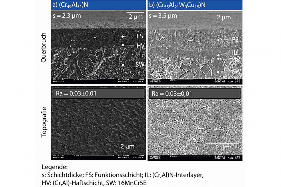
The topography and morphology of the investigated (Cr,Al)N reference coating and the (Cr,Al,W,Cu)N coating are shown in Figure 2. The surfaces of both coatings are finely structured, which can be attributed to the fine columnar growth of the coatings in the coating process, as confirmed by the morphology in the transverse fracture images (Fig. 2). However, differences can be identified in both the surface structure and the morphology depending on the respective coating process. In the reference coating, the influence of the cathodes operated in HPPMS mode predominates, as can be seen from the very dense morphology and the very finely structured surface, whereby individual columns on the surface cannot be distinguished from one another. In contrast, the columns on the surface of the (Cr55Al21W9Cu15)N layer are clearly recognizable. This is due to the use of four cathodes in dc mode during the synthesis of the top layer, while only one cathode is used in dc mode for the (Cr,Al)N reference coating (Table 1).
When comparing the line roughness of both coating systems, the described difference cannot be detected (Fig. 2). Even in comparison to the polished substrate, Ra ≤ 0.02 µm, the measurements show no significant deviations. This illustrates that the coatings have a very smooth surface and that the coating process has no detrimental effect on the surface topography. This is confirmed by the homogeneous structure without significant coating defects on the respective coating surface. At s = 3.5 µm, the thickness of the (Cr55Al21W9Cu15)N coating produced is approximately ∆s = 1 µm more than the reference coating. This can be explained by the additional coating layer and the higher number of dc cathodes in the deposition of the top layer.
 Eindringhärte HIT und b) Eindringmodul EIT der (Cr49Al51)N- und (Cr55Al21W9Cu15)N-Beschichtungen") Fig. 3: a) Indentation hardness HIT and b) Indentation modulus EIT of the (Cr49Al51)N and (Cr55Al21W9Cu15)N coatings
Fig. 3: a) Indentation hardness HIT and b) Indentation modulus EIT of the (Cr49Al51)N and (Cr55Al21W9Cu15)N coatings
|
Coating |
Cr [At.%] |
Al [At.%] |
W [At.%] |
Cu [At.%] |
|
(Cr,Al)N |
49 |
51 |
- |
- |
|
(Cr,Al,W,Cu)N |
55 |
21 |
9 |
15 |
Figure 3 shows the indentation hardness HIT and indentation modulus EIT for the (Cr55Al21W9Cu15)N coating system and the (Cr49Al51)N reference coating determined by nanoindentation. For the (Cr,Al)N reference, a high indentation hardness of HIT = (39.1±3.6) GPa and a high indentation modulus of EIT = (388.5.9±30.3) GPa can be determined using nanoindentation on the basis of 60 measurements. The modification of the (Cr,Al)N matrix with W and Cu leads to a reduction in the indentation hardness HIT and the indentation modulus EIT compared to the reference coating. The nanoindentation measurements show both a moderate indentation hardness of HIT = (22.2±3.3) GPa and a moderate indentation modulus EIT = (285.9±27.1) GPa for the developed (Cr55Al21W9Cu15)N coating. It is expected that, on the one hand, Cu influences the characteristic values. On the other hand, the morphology has a significant influence on the characteristic values determined, so that the operating mode at the cathodes also influences the characteristic values, which is clearly visible from the results. The very dense morphology of the reference coating, which was mainly deposited in HPPMS mode, results in a significantly higher indentation hardness HIT and a higher indentation modulus EIT compared to the modified (Cr55Al21W9Cu15)N coating.
3.1 Bond strength
Finally, to quantify the bond strength, scratch tests were performed on the composite systems (Cr49Al51)N and 16MnCr5E as well as (Cr55Al21W9Cu15)N and 16MnCr5E, the results of which are summarized in Figure 4. At a scratch speed of vR = 10 mm/min and under constant load during the scratch, the first significant plastic deformation of the composite (Cr49Al51)N/16MnCr5E occurred at a critical scratch load of Lc1 = 10 N, while the composite (Cr55Al21W9Cu15)N/16MnCr5E showed the first signs of plastic deformation at Lc1 = 20 N. The first flaking at the edge of the scratch track is visible in the CLSM images in the system with the (Cr49Al51)N coating at Lc2 = 15 N and in the system with the tribocatalytic coating (Cr55Al21W9Cu15)N at Lc2 = 30 N.
N/16MnCr5E, A) und (Cr55Al21W9Cu15)N/16MnCr5E, B)") Fig. 4: Optically determined critical scratch loads Lc1, Lc2 and Lc3 after the scratch tests on the composite systems (Cr49Al51)N/16MnCr5E, A) and (Cr55Al21W9Cu15)N/16MnCr5E, B)
Fig. 4: Optically determined critical scratch loads Lc1, Lc2 and Lc3 after the scratch tests on the composite systems (Cr49Al51)N/16MnCr5E, A) and (Cr55Al21W9Cu15)N/16MnCr5E, B)
At a critical load of Lc3 = 50 N, both coatings are completely penetrated by the scratch diamond down to the substrate. The quantification of the composite adhesion by means of a scratch test thus shows comparable behavior under corresponding load for both composite systems, so that the modification with Cu and W does not adversely affect the composite adhesion of the coating system (Cr55Al21W9Cu15)N on 16MnCr5E. The findings obtained by means of scratch tests thus demonstrate promising adhesion in the respective bond, particularly against the background of deposition of the coating systems in low-temperature processes. Promising composite adhesion between the substrate material and the coating is a necessary prerequisite for using the composites in highly stressed tribological systems.
3.2 Tribological analysis in the (Cr,Al,W,Cu)N/PAO system using a PoD tribometer
Table 5 summarizes the parameters of the PoD tests carried out. The tests carried out with the ceramic counterpart Si3N4 are labeled below with the letter K and the temperature used in the respective test, RK23, RK90, K23, K90. The tests with the steel counterpart 100Cr6 are designated analogously using the letter S, RS23, RS90, S23, S90. In all tests marked with an R, a (Cr49Al51)N-coated (reference) specimen and in all other tests a (Cr55Al21W9Cu15)N-coated specimen made of 16MnCr5E were used.
|
Tests |
Counter body |
Lubricant |
Lubricant Temperature |
|
RK23, K23 |
Si3N4 |
PAO |
23 °C |
|
RK90, K90 |
Si3N4 |
PAO |
90 °C |
|
RS23, S23 |
100Cr6 |
PAO |
23 °C |
|
RS90, S90 |
100Cr6 |
PAO |
90 °C |
 Fig. 5: Variation of the coefficients of friction μ as a function of temperature and mating body for the tribological systems tested
Figure 5 shows the coefficients of friction µ determined in the respective PoD tests plotted over the running distance s. Figure 5a shows all tests with the Si3N4 counter body and Figure 5b with the 100Cr6 counter body. The evaluation of the tests for the Si3N4 counter body shows the lowest coefficients of friction µ for the tests with the tribocatalytic coating system (Cr55Al21W9Cu15)N, (Fig. 5a). While a very short running-in phase is recorded for the test at T = 23 °C, K23, this is significantly longer at a higher temperature, K90, s ≈ 400 m (Fig. 5a). Ultimately, the coefficient of friction µ at the end of the K90 test is slightly below the coefficient of friction µ of the K23 test. The coefficients of friction for the tribological tests with the reference coating (Cr49Al51)N and the Si3N4 counterbody, RK23 and RK90, are around ∆µ ≈ 0.02 higher compared to the tests with the tribocatalytic coating system and are at a similar level for both tested temperatures (Fig. 5a). While the lowest coefficient of friction µ is detected for the tribocatalytic coating system and the Si3N4 counterpart at T = 90 °C, the coefficient of friction µ is lowest for the tribological tests with the reference and Si3N4 at T = 23 °C (Fig. 5a). A higher coefficient of friction at T = 90 °C can be attributed to a reduced viscosity of the lubricant, as this decreases with increasing temperature. As a result, the proportion of solid contact increases in the area of boundary friction. For the tests with the tribocatalytic coating system, this effect does not appear to have a significant influence on the friction behavior (Fig. 5a).
The evaluation of the tribological tests with the 100Cr6 counter body shows a continuously decreasing coefficient of friction µ over the running distance s for the tests with the reference system, whereby comparable coefficients of friction µ are detected at the end of the running distance, RS23 and RS90 (Fig. 5b). Only the running-in behavior varies for the tests carried out. There are clear differences with regard to the curves of the friction coefficients µ of the tests with the tribocatalytic coating system (Cr55Al21W9Cu15)N and the counter body 100Cr6. The very low coefficient of friction µ at a temperature of T = 23 °C, which differs significantly from the tests at T = 90 °C, S23 and S90 (Fig. 5b), is striking. An influence of the Cu modification of the nitride layer on the friction in the form of possible tribocatalytic interactions cannot be clearly proven on the basis of the very different results. While a more promising friction behavior can be observed for the K23, K90 and S23 tests compared to the reference, the coefficient of friction is highest for the S90 system, see Figure 5.
 Fig. 6: Wear marks on coated base bodies as a function of temperature and mating body for the tribological systems investigated at a running distance of s = 1,000 m
Figure 6 shows the wear marks on the coated surfaces recorded following the tribological tests. To quantify the wear volume, the wear area in the profile of the wear track orthogonal to the direction of rotation was determined using CLSM and multiplied by the circumference of the initial sliding path of the ball 2- π -r, with r = 5 mm. The calculated values WVB are shown in Table 6. In addition, the wear on the ball mating body was determined in the form of a wear area WVK (Table 6).
|
Si3N4 counter body |
100Cr6 counter body |
|||||||
|
System |
RK23 |
RK90 |
K23 |
K90 |
RS23 |
RS90 |
S23 |
S90 |
|
Coating wear volume WVB [106 µm3] |
0,92 |
0,37 |
0,34 |
1,06 |
1,18 |
1,63 |
0,13 |
0,44 |
|
Wear surface ball WVK [106 µm2] |
1,7 |
1,1 |
1,1 |
1,9 |
4,3 |
8,8 |
2,4 |
2,9 |
Both the surface of the reference coating and that of the tribocatalytic coating system show only slight wear following the tribological tests. For the reference system, both the wear track images and the calculated wear volume for the tests with the ceramic mating body RK23 and RK90 indicate low wear. For the tests with the 100Cr6 counter body, the determined wear volume WVB is higher than that of the tests with Si3N4 counter bodies. The strips shown in Figures 6c and 6d confirm abrasive wear on the coating. In analogy, abrasive wear was detected for all tests on the counter bodies. Differences are also evident here in relation to the material used for the counter body. The wear on the Si3N4 counter-bodies for the tests with the reference coating is lower than on the 100Cr6 counter-bodies (Table 6). This means that the wear on the coating and on the mating body correlate with the reference coating in all tests. For the tribological tests with the coating system (Cr55Al21W9Cu15)N, the differences in terms of wear on the mating body are less significant. However, abrasive wear can also be detected in this respect after all tests, which is higher for the 100Cr6 counter bodies than on the respective Si3N4 balls.
Comparable findings can be taken from the images of the wear tracks of the tests carried out with the tribocatalytic coating system (Cr55Al21W9Cu15)N. Following the tests with the ceramic counter body, a clear, narrow wear track can be identified in each case, the width of which is dependent on the temperature. This is again due to the temperature dependence of the lubricant viscosity. While the wear at T = 23 °C is higher for the reference coating in relation to the tests with Si3N4 (RK23 and RK90), higher wear at higher temperatures can be seen for the system with (Cr55Al21W9Cu15)N (K23 and K90). The use of a tribological contact partner made of steel leads to very low wear in the tests with the coating system (Cr55Al21W9Cu15)N (S23 and S90), which is lowest at T = 23 °C (S23). When analyzing the wear tracks of the system (Cr55Al21W9Cu15)N, a dark coloration of the tracks becomes visible, which were carried out with the counter body 100Cr6. The examination of the base and counter body shows both abrasive and adhesive wear, so that the coloration can be explained by the partial material transfer.
Figure 7 shows the Raman spectra for the tribological systems in order to investigate the tribocatalytic interactions between the (Cr49Al51)N or (Cr55Al21W9Cu15)N layer and the additive-free lubricant PAO. The results of two measurements per system are shown, all of which were carried out in the wear track.
N- und (Cr55Al21W9Cu15)N-Beschichtungen und additivfreiem PAO in Abhängigkeit der Temperatur und des Gegenkörpers mittels zweier Raman-Spektren je System") Fig. 7: Evaluation of the tribocatalytic interactions between the (Cr49Al51)N and (Cr55Al21W9Cu15)N coatings and additive-free PAO as a function of temperature and the mating body using two Raman spectra per system
Fig. 7: Evaluation of the tribocatalytic interactions between the (Cr49Al51)N and (Cr55Al21W9Cu15)N coatings and additive-free PAO as a function of temperature and the mating body using two Raman spectra per system
All Raman spectra show the (Cr,Al)N matrix independent of the PoD test parameters. Corresponding peak positions for the (Cr,Al)N matrix have already been confirmed by Sánchez-López et al [5]. Regardless of the counter body and the test temperature, comparable Raman spectra are determined for the reference layer system (Cr49Al51)N, which also detect amorphous carbon in addition to the (Cr,Al)N matrix. The position of the determined peak agrees with the peak position for amorphous carbon bonds detected in work by Korepanov et al [6]. The C-bonds can be attributed to residues of the lubricant PAO.
In contrast, clear differences can be observed between the spectra for the experiments with the layer system (Cr55Al21W9Cu15)N depending on the counter body used and the temperature. The Raman analyses following the experiments confirm the formation of the copper-sulphur compound Cu7S4 by comparison with data from Lafuente et al. in [7], whereby the low peak intensities suggest only low proportions of Cu7S4. Sulphur, with a content of xs = 1.39 wt.%, is contained in the lubricant PAO for stabilization despite the classification "additive-free", so that a reaction of the sulphur from the lubricant with the Cu from the coating is possible. As already observed with the reference system, amorphous carbon in the form of PAO residues can be detected in the wear track of system K23. The formation of tribochemical reaction layers cannot be proven in system K23. The spectra following the PoD tests of systems K90 and S23 also show no evidence of tribocatalytic interactions between lubricant and coating. In contrast, the results of the Raman spectroscopy clearly stand out with regard to the S90 system. In addition to the (Cr,Al)N matrix and the Cu7S4 compound, further peaks are recognizable. The comparison with data from Lafuente et al. in [8] confirms the formation of Fe2O3. Furthermore, the comparison of the spectra with spectra from work by Dychalska et al [9] shows carbon compounds whose structure is comparable to DLC coatings. This can be demonstrated by the D (disorderd, 1,580 cm-1 ≤ ϑ ≤ 1,600 cm-1) and G (graphitic, 1,305 cm-1 ≤ ϑ ≤ 1,350 cm-1) peaks typical of DLC coatings in the Raman spectra of the S90 system. This may indicate tribocatalytic interactions between the (Cr55Al21W9Cu15)N coating and PAO, which lead to the formation of layers of diamond-like carbon in the wear track.
The formation of tribocatalytically induced reaction layers correlates with the formation of Fe2O3 in tribological contact at T = 90 °C. It is therefore assumed that the presence of Fe and elevated temperatures are of fundamental importance for the tribocatalytic interaction. While in almost all systems the wear on the mating body and coating is lower for the tests with the coating system (Cr55Al21W9Cu15)N than for the corresponding tests with the reference, no positive influence of the reaction layer formation on the friction can be demonstrated. The correlation of the Raman spectroscopy results with the determined friction coefficients shows that the reaction products formed appear to have a detrimental effect on the friction behavior. While low coefficients of friction compared to the reference can be determined for the tribological tests without evidence of interactions between PAO and (Cr55Al21W9Cu15)N and independently of the counter body, the coefficient of friction for the S90 system is significantly higher. A friction reduction via a tribochemically induced reaction layer formation can therefore not be proven at this point.
4 Summary
To enable the tribocatalytic interaction between nitride PVD coatings and lubricants, a (Cr,Al,W)N matrix was modified with Cu. The Cu has the function of interacting with the lubricant and causing the transformation of the molecular chains of the base oil. The investigations prove that the formation of tribocatalytic reaction layers, comparable to DLC coatings, is possible. In addition to Cu, the presence of Fe in the tribological contact and a certain activation energy appear to be necessary for the tribocatalytic reactions. The latter is influenced by the pressure in the contact and the temperature. However, a positive influence of the reaction layer formation on friction could not be proven. Rather, although wear can be largely reduced compared to a (Cr,Al)N reference, the tribo-induced reaction layer formation is accompanied by an increase in the coefficient of friction.
5 Acknowledgments
The authors gratefully acknowledge the financial support of the German Research Foundation (DFG) as part of the research project "Triboactive and tribocatalytic (Cr,Al)N coatings", BO 1979/65-1.
Literature
[5] J.C. Sánchez-López; A. Contreras; S. Domínguez-Meister; A. García-Luis; M. Brizuela: Tribological behavior at high temperature of hard CrAlN coatings doped with Y or Zr, Thin Solid Films 550 (2014) 413-420
[6] V. Korepanov; H. Hamaguchi; E. Osawa; V. Ermolenkov; I.K. Lednev; B.J.M. Etzold; O. Levinson; B. Zousma; C. PrakashEpperla; H.-C. Chang: Carbon structure in nanodiamonds elucidated from Raman spectroscopy, Carbon, 121 (2017) 322-329, https://doi.org/10.1016/j.carbon.2017.06.012
[7] B. Lafuente; R.T. Downs; H. Yang; N. Stone: The power of databases: the RRUFF project, in: T. Armbruster; R.M. Danisi: Highlights in Mineralogical Crystallography, (2015), W. De Gruyter, Berlin, Germany, 1-30, RRUFF ID R060514
[8] B. Lafuente; R.T. Downs; H. Yang; N. Stone: The power of databases: the RRUFF project, in: T. Armbruster; R.M. Danisi: Highlights in Mineralogical Crystallography, (2015), W. De Gruyter, Berlin, Germany, 1-30, RRUFF ID X050102
[9] A. Dychalska; P. Popielarski; W. Frankow; K. Fabisiak; K. Paprocki; M. Szybowicz: Study of CVD diamond layers with amorphous carbon admixture by Raman scattering spectroscopy, Material Science-Poland, 33, 4, (2015) 799-805, https://doi.org/10.1515/msp-2015-0067
