
At the Research Institute for Precious Metals and Metal Chemistry (fem), computed tomography (CT) is used as a non-destructive method for materials testing for a wide range of applications in industry and research. Both manufacturing and surface technology as well as battery and fuel cell research benefit from the use of this method. Two systems are available: the v|tome|x L with a 300 kV X-ray tube and the Nanotom M with a 180 kV tube.
Computed tomography is a technologically extremely demanding process that has so far been characterized by high technical and time expenditure. The interaction between the hardware and software of the CT system has a decisive influence on imaging. By procuring a new detector (Dynamic 4.1), a drastic reduction in measurement time, significantly better data quality and therefore shorter processing times have been achieved. The Dynamic 4.1 detector with its pixel size of 200 µm and significantly higher sensitivity in combination with a powerful evaluation computer increases the application possibilities and the efficiency of data processing.
In recent years, various topics and materials have been investigated at the fem in various projects and in collaboration with industry.
X-ray computed tomography provides the user with information about
- Surface condition
- material properties
- distribution
- Position of the components in relation to each other
- tightness
- Shape accuracy
- Porosity
- Manufacturing defects
To illustrate the wide range of possible applications of CT examinations, here are some examples of applications.
In the project "Construction of new three-dimensional cathodes for lithium-sulphur batteries with increased capacity, energy efficiency and cycle stability", the distribution of dispersion sulphur on dispersion-coated nickel foams was clearly highlighted with the help of CT examinations. In the course of the project, the distribution of the sulphur (Fig. 1) and the homogeneity were analyzed and the efficiency of the coating was demonstrated.
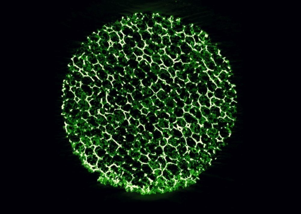 Fig. 1: Sulphur distribution on a nickel foam/AiF/IGF 18127N
In the project "Development of a microbipolar element arrangement that can be integrated using LIGA technology with minimal use of precious metals to simplify the design and manufacture of self-breathing fuel cell stacks for portable electronics applications", CT was able to provide helpful information. Non-destructive testing enabled the layer structure of the structures and the homogeneous filling with metal to be visualized (Fig. 2). CT thus proved to be a suitable method for quality assurance in the manufacture of the bipolar plates and for quality control of the coating.
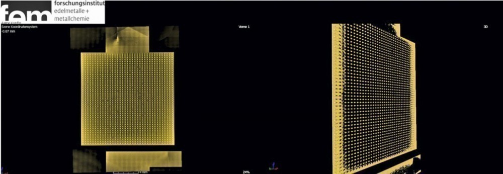 Fig. 2: 3D representation of the internal structures in micro fuel cells/AiF IGF 448ZN
In the "Selective laser melting of gold alloys" project, the CT process was used to visualize internal, volume-related defects with spatial resolution (Fig. 3). This means that production using SLM can be monitored, documented and evaluated. Due to the high geometric resolution and seamless recording, CT can be used as a tool to adequately describe the quality of components.
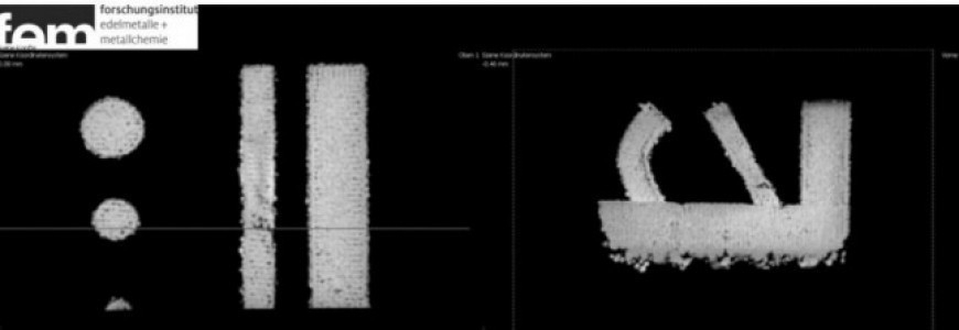 Fig. 3: SLM sample with internal porosity/AiF IGF 17729N
CT was also used efficiently in the work "Research into the causes of paint defects in cast parts". The CT was able to identify a connection between individual bubble nests and larger "cavities" and clarify the cause of the paint defects. The hydrogen in the bubbles outgasses from the bubble cavities and causes paint defects. The cavities or bubbles, which lie at a depth of up to 2 mm from the surface, can contribute to the defects. It could be clearly shown that there must be connecting channels between the cavity and paint defects or that the material must be weakened for paint defects to occur (Fig. 4).
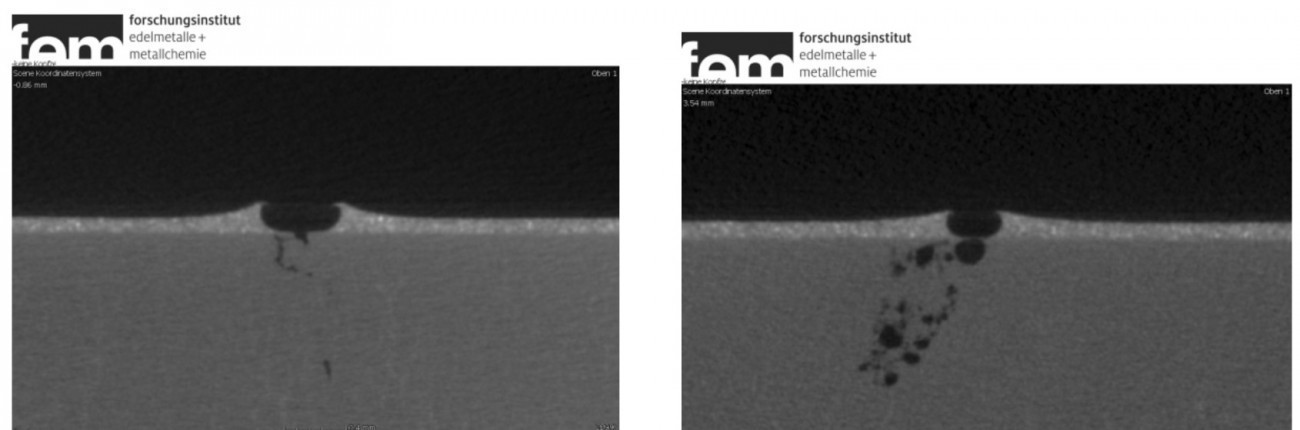 Fig. 4: Bubble nests with a connection to the surface/IGF 17714N
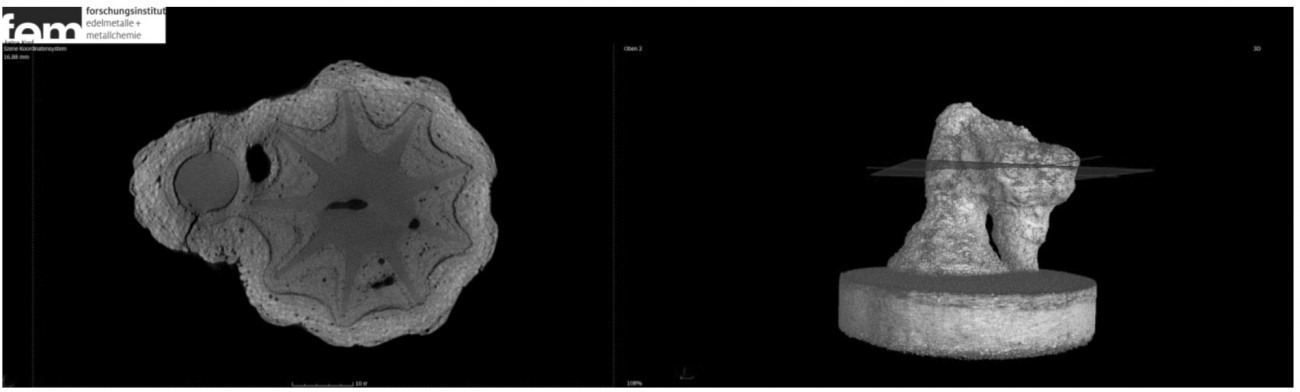 Fig. 5: Cross-section through a filled mold shell. Cracks and filling gaps visible/AiF 18293GB
As shown in the examples, computed tomography can be used in many ways, quickly and non-destructively as a helpful method for many problems.
