- Part 2 - Electroforming with rotating substrate, results, discussion, summary and outlook / continued from Galvanotechnik 2/2024
The experimental work presented in the first part on the development of a manufacturing process for aluminum foils using electroforming is completed at the beginning of this second and final part, followed by the summary. The aluminum is deposited in an ionic liquid. Electroforming is investigated on substrates made of different materials and with different geometries. By characterizing the films using light and scanning electron microscopy, correlations between the deposition conditions and the microstructure of the films can be established.
Electroforming with a rotating substrate
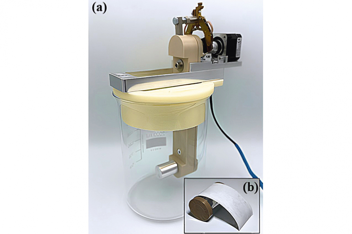
For electroforming with a rotating substrate, a beaker attachment was also designed using CAD and produced from polyvinyl alcohol using 3D printing in order to facilitate handling in the glovebox. Parallel slots were cut into the side of the attachment to attach the counter electrodes and holes were made for the temperature sensor of the heating plate and the reference electrode. There were also holes for guiding and centrally positioning the product carrier. An additional aluminum frame was made for the product carrier, to which it was attached with a screw. The stepper motor, which is responsible for the rotation of the substrate, was screwed to the upper shaft of the product carrier and also attached to the aluminum frame. In combination with the guide holes in the beaker attachment, the frame is used for easy insertion and removal of the substrate into and out of the electrolyte. At the same time, reproducible positioning in the electrolyte and equal distances to the anodes are ensured. Based on the results of the tests with planar substrates, high-alloy steel 1.4301 was selected for the cylinder substrates. Figure 5 shows a) the product carrier with aluminum cylinder used in the beaker, onto which the cylinder shown in b) with partially detached aluminum foil was pressed. For clarity, the counter and reference electrodes and the temperature sensor are not shown. As in the preliminary tests, sheet metal blanks made of 2.0 mm thick aluminum (192 cm x 30 mm) or an aluminum wire cast in a Pasteur pipette were used as counter and reference electrodes.
Before the deposition tests, the cylinder substrates were first sanded using sandpaper (180, 320, 800, 1200, 2500 grit) until a high-gloss surface with no visible defects was achieved. After sanding, the cylinders were rinsed with deionized water and isopropanol and dried with compressed air. The edges of the cylinder were taped with PTFE adhesive tape to obtain clean edges. In addition, a transverse strip was covered with PTFE tape. The free substrate area was approx. 21.7 cm2.
For the experiments, 1000 ml of the electrolyte was poured into a 2000 ml beaker and the temperature was set to 50 °C. The electrolyte was stirred with a stirrer. The electrolyte was stirred with a 40 mm long magnetic stirring bar at 250 rpm. The target layer thickness was set at 20 μm in order to increase the mechanical stability of the electroformed films. The parameters mentioned here remained constant across all tests. The rotation speed of the substrate and the current density were varied. Table 3 provides an overview of the parameter combinations used.
|
Substrate rotation speed [rpm] |
Current density |
|
20 |
5,0 |
|
20 |
10,0 |
|
20 |
15,0 |
|
10 |
5,0 |
|
10 |
10,0 |
|
10 |
15,0 |
|
1 |
5,0 |
|
1 |
10,0 |
|
1 |
15,0 |
|
1 |
20,0 |
Table 3: Overview of the parameter combinations for electroforming with a rotating substrate. Electrolyte temperature and stirring speed remained constant at 50 °C and approx. 250 rpm
After deposition, the product carrier was removed from the electrolyte and waited until most of the adhering electrolyte had dripped off. The substrate was then rinsed in three stages. For this purpose, the substrate was successively immersed in three rinses with dichloromethane (99.8+ %, Acros Organics, Geel, Belgium) at 30 rpm for 30 s each. The dichloromethane was dried with molecular sieve (pore diameter 4 Å, Carl Roth GmbH + Co. KG, Karlsruhe, Germany) before use as a rinsing medium to prevent hydrolysis of the electrolyte with residual water. The substrate was then removed from the product carrier, discharged and rinsed with deionized water outside the glovebox. The PTFE film was also removed from the cylinder. A scalpel was used to remove the aluminum layer from the substrate. The removed aluminum layer was then rinsed again with deionized water and dried overnight in an open container.
Results of electroforming with a planar substrate
Experiments on the electroforming of 15 µm thick aluminum foils were carried out using the presented test setup and substrates made of different materials. After the depositions, the substrates were rinsed and dried before the aluminum layers were detached from the substrate. Figure 6 shows the aluminum foils obtained with unalloyed steel, high-alloyed steel, molybdenum and glassy carbon. The foil electroformed with unalloyed steel adhered comparatively strongly to the substrate and had to be pulled off the substrate with the fingers, whereby it deformed mechanically. poliertem und passiviertem unlegierten, b) poliertem und passiviertem hochlegierten Stahl, c) Molybdän und d) Glassy Carbon. Die Elektrolyttemperatur betrug 50 °C, die Rührgeschwindigkeit ca. 250 U/min und die Stromdichten lagen bei 16,9 ± 0,7 mA/cm2") Fig. 6: Electroformed aluminum foils with substrates made of a) polished and passivated unalloyed, b) polished and passivated high-alloyed steel, c) molybdenum and d) glassy carbon. The electrolyte temperature was 50 °C, the stirring speed was approx. 250 rpm and the current densities were 16.9 ± 0.7 mA/cm2
Fig. 6: Electroformed aluminum foils with substrates made of a) polished and passivated unalloyed, b) polished and passivated high-alloyed steel, c) molybdenum and d) glassy carbon. The electrolyte temperature was 50 °C, the stirring speed was approx. 250 rpm and the current densities were 16.9 ± 0.7 mA/cm2
Electroforming with rotating substrate
20 µm thick aluminum layers were deposited on rotating cylindrical substrates made of high-alloy, polished steel, assuming 100 % efficiency. The current density and the rotation speed of the substrate were varied. An attempt was then made to remove the layer from the substrate. It was noticeable that this was not possible for any layer deposited at 5.0 mA/cm2. Furthermore, all films produced with 10 mA/cm2 showed a pronounced porosity. Compact aluminum foils could only be electroformed at current densities of 15 or 20 mA/cm2. A camera image of an aluminum foil electroformed at 20 rpm and 15 mA/cm2 is shown in Figure 7. Fig. 7: Camera image of an aluminum foil electroformed at 20 rpm and 15 mA/cm2
During the depositions, the potential was recorded against an aluminum reference electrode. Selected potential curves are shown in Figures 8 and 9 in order to show the correlations between the deposition parameters and the potential curves. Before plotting, the raw data was adjusted for some strong, cyclical downward deflections, but these could not be completely removed. Figure 8 shows the potential curves for different current densities at a constant rotation speed of 1 rpm. This shows an almost
directly proportional relationship between the current densities and the resulting potentials. With every increase in current density by 5.0 mA/cm2, the potential becomes approx. 200 mV more negative. This dependence can also be seen at the two other rotation speeds of 10 and 20 rpm, which are not listed here.
 5,0 mA/cm2, (■■■■ ) 10 mA/cm2, (■■■■ ) 15 mA/cm2 und (■■■■ ) 20 mA/cm2") Fig. 8: Potential curves during aluminum deposition with a substrate rotation speed of 1 rpm and (blue ) 5.0 mA/cm2, (orange ) 10 mA/cm2, (grey ) 15 mA/cm2 and (yellow ) 20 mA/cm2
Fig. 8: Potential curves during aluminum deposition with a substrate rotation speed of 1 rpm and (blue ) 5.0 mA/cm2, (orange ) 10 mA/cm2, (grey ) 15 mA/cm2 and (yellow ) 20 mA/cm2
 1,0 U/min, (■■■■ ) 10 U/min und (■■■■ ) 20 U/min") Fig. 9: Potential curves during aluminum deposition with a current density of 15 mA/cm2 and rotation speeds of the substrate of (green ) 1.0 rpm, (red ) 10 rpm and (blue ) 20 rpm
Fig. 9: Potential curves during aluminum deposition with a current density of 15 mA/cm2 and rotation speeds of the substrate of (green ) 1.0 rpm, (red ) 10 rpm and (blue ) 20 rpm
Figure 9 shows the potential curves at a constant current density of 15 mA/cm2 and varying rotational speed. At the beginning of deposition, no clear pattern can be recognized, as the potential for deposition at 20 rpm lies between those at 1 and 10 rpm. Only after a few minutes does it become apparent that the potential becomes more negative as the rotational speed increases. However, there does not appear to be any proportionality, as there is, for example, between current density and potential. At a current density of 10 mA/cm2, the potential curves for 1 and 10 rpm overlap, whereas the potential curve for 20 rpm runs parallel to it with a downward offset of approx. 100 mV. For the current density of 5.0 mA/cm², the potential curve for 20 rpm approaches even more closely and almost covers the other two. und 800x (oberes Bild) Vergrößerung von galvanogeformten Aluminiumfolien abgeschieden mit a) 1 U/min und 20 mA/cm2, b) 1 U/min und 10 mA/cm2 sowie c) 20 U/min und 10 mA/cm2") Fig. 10: Light microscope images of cross-sections at 200x (lower image) and 800x (upper image) magnification of electroformed aluminum foils deposited at a) 1 rpm and 20 mA/cm2, b) 1 rpm and 10 mA/cm2 and c) 20 rpm and 10 mA/cm2
Fig. 10: Light microscope images of cross-sections at 200x (lower image) and 800x (upper image) magnification of electroformed aluminum foils deposited at a) 1 rpm and 20 mA/cm2, b) 1 rpm and 10 mA/cm2 and c) 20 rpm and 10 mA/cm2
Figure 10 shows microscope images of cross-sections of various aluminum foils at 200x (lower image) and 800x magnification (upper image). Shown are images of electroformed aluminum foils, deposited at a) 1 rpm and 20 mA/cm2, b) 1 rpm and 10 mA/cm2 and c) 20 rpm and 10 mA/cm2. The figure shows that the electroformed films have a smooth underside and, depending on the deposition conditions, a relatively smooth to highly structured upper side. In particular, the films in figures b) and c) show the presence of pores in the electroformed films. It is obvious that the roughness strongly depends on the deposition parameters of the aluminum layer. A comparison of images a) and b) shows that at a constant rotational speed of the cylindrical substrate, a higher current density leads to a less structured surface. The rotational speed of the substrate cylinder also influences the roughness. The film in figure b) was produced at a lower rotational speed than the film in figure c) and therefore appears more compact and homogeneous. In addition, image c) shows a larger proportion of pores compared to image b).
Figure 11 shows SEM images of the same aluminum foils. The naming of images a) to c) is analogous to Figure 10. As can be seen, the grain size of the electrodeposited aluminum increases from image a) to c). In image a), the grains have a predominantly fine structure, with occasional coarser grains scattered over the surface. In contrast, picture c) shows a pronounced grain structure characterized by the presence of very large grains. Image b) shows an intermediate state between images a) and c). It includes a combination of fine and coarse grains. 1 U/min und 20 mA/cm2, b) 1 U/min und 10 mA/cm2 sowie c) 20 U/min und 10 mA/cm2.") Fig. 11: SEM images of electroformed aluminum foils deposited at a) 1 rpm and 20 mA/cm2, b) 1 rpm and 10 mA/cm2 and c) 20 rpm and 10 mA/cm2.
Fig. 11: SEM images of electroformed aluminum foils deposited at a) 1 rpm and 20 mA/cm2, b) 1 rpm and 10 mA/cm2 and c) 20 rpm and 10 mA/cm2.
Discussion
First, preliminary tests were carried out on the electroforming of 15 µm thick aluminum foils with a planar substrate. Passivated unalloyed and high-alloyed steel, molybdenum and glassy carbon were selected as potential substrate materials. It was shown that, with the exception of unalloyed steel, all materials are suitable in principle (see Figure 6). The further tests with a rotating substrate were carried out with high-alloy steel as the substrate material due to its advantageous properties (including ease of processing and low cost) compared to the other materials.
For electroforming with a rotating substrate, a test setup was developed that allows foils with a larger surface area to be produced. This was used to electroform aluminum foils with a target layer thickness of 20 µm (assuming 100 % efficiency). Different current densities and rotation speeds of the substrate were used. This showed that the layers deposited at 5 mA/cm2 did not exhibit any cohesion and could not be detached from the substrate. Regardless of the rotation speed, films with pronounced porosity were obtained with 10 mA/cm2 and dense films with 15 or 20 mA/cm2. The cathode potentials recorded during the depositions show a linear dependence on the current density (see Figure 8). There appears to be no proportionality between potential and rotation speed. The values of the potential in Figure 9 initially appear counterintuitive, as the potential becomes more negative with higher rotational speed. It could have been expected that this would be exactly the opposite, as the Nernst diffusion layer is thinner with faster substrate rotation than with slower substrate rotation. Accordingly, the diffusion overvoltage should be lower and thus also the total overvoltage, which is recorded together with the voltage drop across the electrolyte and the product carrier in the potential measurement. As explained in the previous sentences in Figure 9, the difference between the potentials at different rotation speeds decreases with decreasing current density and is sometimes even congruent. A possible reason for this is that the ohmic resistance of the product carrier also increases with increasing rotational speed, which exceeds the effects of the rotational speed on the diffusion overvoltage.
A selection of electroformed films was characterized in more detail to reveal relationships between the deposition conditions and the resulting microstructure. As shown in Figure 10, the structure and porosity of the films strongly depend on the deposition conditions. The rotation speed has a smaller influence than the current density, whereby the proportion of pores in the film also decreases with decreasing rotation speed. The former becomes understandable when one considers that the overvoltage also depends almost exclusively on the current density. Higher overvoltages lead (within certain limits) to finer-grained and therefore more compact and smoother layers. This can be confirmed in particular with the SEM images of the films (see Figure 11) and the decreasing roughness can be attributed to the finer-grained layer.
The decrease in both the roughness and the proportion of pores by increasing the current density and/or reducing the rotational speed of the cylinder can be explained by the dependence of the thermodynamics and kinetics of electrocrystallization on these parameters: Higher current densities and lower rotation speeds lead to a more negative overvoltage in aluminium deposition due to concentration polarization. With an increase in the absolute value of the overvoltage, the Gibbs energy ∆g_krit, which is required to form a nucleus with the critical nucleation radius, decreases. This relationship is shown in equation 1. In it, π is the circle number, V_M is the molar volume of the layer metal, σ is the free surface enthalpy of the nucleus, z is the charge of the ions of the layer metal, F is the Faraday constant and η is the overvoltage.
∆g_krit=8π/3 (V_M^2)/(z^2 F^2 ) σ^3/|η|^2<1>
At lower Gibbs energy, the nucleation rate v_KB increases according to the Arrhenius law in equation <2>. It is the nucleation constant A_K, which represents the highest possible nucleation frequency, k_B is the Boltzmann constant and T is the absolute temperature.
v_KB=A_K exp(-(∆g_krit)/(k_B T))=
A_K exp(-8π/3 (V_M^2)/((k_B Tz)^2
F^2) σ^3/|η|^2 )<2>
Consequently, deposition parameters that lead to greater overstress favor the formation of more nuclei on the surface [27,28,29] and lead to a denser (less porous), finer-grained and smoother layer, which can be confirmed by the results shown. Films with the desired porosity, roughness and grain size can therefore be produced by adjusting the rotation speed and current density.
Summary and outlook
In this work, the electroforming of aluminum foils was first investigated on a planar substrate. It was shown that various substrate materials are suitable. High-alloy steel was chosen as a cost-effective and easy-to-machine material for further work. This made it possible to produce free-standing aluminum foils. The next step was to develop a test setup with a rotating cylindrical substrate. Due to the different geometric and convective conditions compared to a planar substrate, a series of tests was carried out on electroforming by varying the current density and rotational speed of the substrate. Low current densities led to non-cohesive layers that could not be detached from the substrate. Medium current densities allowed the layers to detach. These were highly porous. Compact films could only be electroformed at high current densities. Selected films were used to investigate the influence of current density and rotation speed on the roughness and porosity of the layers. Using SEM, it was shown that the relationships can be traced back to the ratio of nucleation to nucleus growth and thus the crystallite size. High current densities and low rotation speeds led to dense, fine-grained layers with low roughness. The opposite is true for low current densities and high rotation speeds. The next steps in the project are to produce composite films with different particles. The focus here is on working out the relationship between the film structure and the conductivity of the particles. Our hypothesis, derived from experience with composite electroformed nickel/sulphur cathodes, is that a partially electrically conductive particle surface allows partial bonding of the particles to the metal matrix, while the particles in the battery application remain so accessible to the battery electrolyte that they can be used electrochemically for energy storage with a high yield. In order to investigate the influence of particle conductivity on layer growth, experiments are first carried out on composite electroforming with electrically insulating particles (e.g. diamond) and electrically conductive particles (e.g. nickel). On this basis, typical active material particles for lithium-ion batteries such as NMC (LiNixMnyCozO2) or NCA (LiNi0.8Co0.15Al0.05O2) are then functionalized in such a way that they have the surface properties required for structured growth while maintaining high accessibility. The composite films produced in this way are characterized both metallographically and electrochemically and tested for their suitability as battery electrodes, especially for cells with very high power density.
Literature
[27] Plieth, W. : The Galvanic Process. Fundamentals of metal deposition and structure formation, 1st edition, Leuze Verlag, Bad Saulgau, Germany, (2018)
[28] Paunovic, M.,Schlesinger, M. : Fundamentals of Electrochemical Deposition, 1st edition, Wiley, New York, NY, USA; Weinheim, Germany, (1998)
[29] Plieth, W.: Electrochemistry for Materials Science, 1st edition, Elsevier, Amsterdam, The Netherlands; Boston, MA, USA, (2008)
