When it comes to the energy storage systems of the future, the question is not only which materials have the best electrochemical properties, but also how central cell components can be produced as resource-efficiently, cost-effectively and efficiently as possible. This is precisely where electroplating technology comes into play. The electrochemical deposition of metals and functional layers is an industrially proven process that is versatile, scalable and technically mature. The technology also plays a central role in post-lithium batteries based on calcium, as studies at the fem Research Institute in collaboration with Aalen University have shown.
Electroplating technology is already being used in hydrogen technology, for example in electrolysers or fuel cells, to deposit catalysts such as iridium or platinum on substrates in a targeted and material-saving manner [1, 2]. This creates highly active layers with minimal use of precious metals, a clear advantage in times of limited availability of raw materials. However, the process has also long been used in other electrochemical storage systems such as redox flow batteries or supercapacitors. There, for example, it ensures the activation of electrode surfaces that contribute directly to energy storage. The advantages are obvious: precise control of the layer structure, high energy efficiency and a good ecological footprint. And best of all, these strengths can also be transferred to new battery concepts, such as calcium-based battery systems.
Calcium, the underestimated element for the battery of tomorrow?
As a representative of the post-lithium generation, calcium offers a promising foundation for a more sustainable battery technology of tomorrow as a cost-effective, abundantly available raw material with a high energy density. However, instead of relying on conventional metal foils as an anode, the fem Research Institute is pursuing a different approach: the targeted electrolytic deposition of thin calcium layers directly onto a current collector. Galvanic deposition opens up a completely new approach here. Instead of using solid metal foils, which are difficult to produce in the case of calcium, thin, functional calcium layers can be deposited directly onto the desired surface. The decisive factor here is controlling the process parameters. The focus of a development by the Institute for Precious Metals and Metal Chemistry (fem) and the Center for Electrochemical Surface Technology (ZEO) at Aalen University is therefore the systematic investigation of the deposition parameters: How do substrate pretreatment, current density, electrolyte movement or charge density influence the morphology of the calcium layers? The results show: Even a mechanically structured surface promotes homogeneous nucleation, higher current densities improve surface coverage and targeted stirring processes favor compact layer structures [3]. The conclusion: if you control the process precisely, you can influence the quality of the calcium anode in a targeted manner. With this goal in mind, the researchers are working to contribute to the development of safe, efficient, economical and sustainable new battery concepts.
The right electrolyte as the key to feasibility
![Abb. 1: Vergleich verschiedener Calcium-Elektrolyte: Während konventionelle Systeme wie Ca(TFSI)2 in EC/PC durch hohe Überspannungen und geringe Reversibilität limitiert sind, zeigen speziell entwickelte Elektrolyte wie Ca[B(hfip)4]2 in DME und Ca(BH4)2 in THF deutlich bessere Abscheideeigenschaften. Letzteres ermöglicht zudem eine vollflächige Schichtbildung, ein vielversprechender Ansatz für die Entwicklung stabiler Calcium-Anoden - Aufnahmen und Grafiken: fem gt 2025 09 29](/images/stories/Abo-2025-09/thumbnails/thumb_gt-2025-09-29.jpg) Fig. 1: Comparison of different calcium electrolytes: While conventional systems such as Ca(TFSI)2 in EC/PC are limited by high overvoltages and low reversibility, specially developed electrolytes such as Ca[B(hfip)4]2 in DME and Ca(BH4)2 in THF show significantly better deposition properties. The latter also enables full-surface layer formation, a promising approach for the development of stable calcium anodes - photos and graphics: fem Before metallic calcium can work efficiently in a battery, it must be able to do one thing reliably: it must be able to be reversibly deposited and dissolved again, i.e. "plating" and "stripping", as it is known in the industry. Whether this is successful depends heavily on the electrolyte used. For this reason, various formulations were systematically put to the test at the fem Research Institute in the first stage of the work. The focus was on two key parameters: the Coulomb efficiency, the ratio between the amount of charge charged and discharged in the subsequent cycle, and the overvoltage, the additional energy required to balance the electrode equilibrium and generate a net material conversion. Both parameters provide information on how stable and efficient the system is. The results are clear: conventional electrolytes from lithium battery technology cannot simply be transferred to calcium (Fig. 1). This becomes particularly clear with the example of Ca(TFSI)2 in EC/PC, an electrolyte system that is widely used in lithium-ion batteries with Li+as the charge carrier, but in the case of Ca2+ as the charge carrier leads to a sharp increase in cell voltage and does not enable metal deposition. The efficiency is low and the overvoltages are high. Why? The reason lies in the formation of a so-called passive SEI layer (solid electrolyte interphase). This is created by side reactions of the electrolyte on the electrode surface and acts as a convergence layer like a barrier. The SEI enables ion transport and blocks electrons in order to prevent further decomposition of the electrolyte and ensure the continuation of the electrochemical reaction. In the case of calcium, however, it is problematic: in carbonate-based electrolytes, the SEI tends to form calcium carbonates, which hardly contribute to ionic conductivity. For practical use, this is a real "showstopper" that blocks the process.
Fig. 1: Comparison of different calcium electrolytes: While conventional systems such as Ca(TFSI)2 in EC/PC are limited by high overvoltages and low reversibility, specially developed electrolytes such as Ca[B(hfip)4]2 in DME and Ca(BH4)2 in THF show significantly better deposition properties. The latter also enables full-surface layer formation, a promising approach for the development of stable calcium anodes - photos and graphics: fem Before metallic calcium can work efficiently in a battery, it must be able to do one thing reliably: it must be able to be reversibly deposited and dissolved again, i.e. "plating" and "stripping", as it is known in the industry. Whether this is successful depends heavily on the electrolyte used. For this reason, various formulations were systematically put to the test at the fem Research Institute in the first stage of the work. The focus was on two key parameters: the Coulomb efficiency, the ratio between the amount of charge charged and discharged in the subsequent cycle, and the overvoltage, the additional energy required to balance the electrode equilibrium and generate a net material conversion. Both parameters provide information on how stable and efficient the system is. The results are clear: conventional electrolytes from lithium battery technology cannot simply be transferred to calcium (Fig. 1). This becomes particularly clear with the example of Ca(TFSI)2 in EC/PC, an electrolyte system that is widely used in lithium-ion batteries with Li+as the charge carrier, but in the case of Ca2+ as the charge carrier leads to a sharp increase in cell voltage and does not enable metal deposition. The efficiency is low and the overvoltages are high. Why? The reason lies in the formation of a so-called passive SEI layer (solid electrolyte interphase). This is created by side reactions of the electrolyte on the electrode surface and acts as a convergence layer like a barrier. The SEI enables ion transport and blocks electrons in order to prevent further decomposition of the electrolyte and ensure the continuation of the electrochemical reaction. In the case of calcium, however, it is problematic: in carbonate-based electrolytes, the SEI tends to form calcium carbonates, which hardly contribute to ionic conductivity. For practical use, this is a real "showstopper" that blocks the process.
Not all electrolytes fail at calcium plating and stripping, on the contrary: some formulations show that it can be done differently. The Ca[B(hfip)4]2 system in DME, i.e. 1,2-dimethoxyethane, was particularly convincing in our investigations. Compared to conventional electrolytes containing carbonate, calcium could be deposited and removed much more efficiently and with less overvoltage. At the same time, the electrochemical reversibility improved, a clear advance towards a practical calcium anode [4]. What is the reason for this? One reason is the more favorable complexation behavior of the calcium ion in this electrolyte. Put simply, the calcium is not too tightly bound here, but moves flexibly enough to be efficiently deposited on the electrode. At the same time, the special structure of the anion, in particular the stable carbon-fluorine bonds, ensures that the electrolyte is more oxidatively robust. This reduces the likelihood of disruptive side reactions that would otherwise lead to passivation of the surface. The Ca(BH4)2 system in THF, i.e. tetrahydrofuran, which was the most powerful electrolyte in our tests, went a step further. Here we observed the highest deposition efficiency with the lowest overvoltages. The reason: a particularly advantageous SEI layer that forms during the process. This layer acts like a selective filter, allowing calcium ions to pass through while at the same time protecting the electrode from decomposing reactions with the electrolyte. It is precisely this combination that makes the system so exciting and at the same time worthy of discussion. Although the performance in the laboratory is impressive, reproducibility has so far been limited. Experts are therefore intensively discussing the conditions under which Ca(BH4)2/THF can be used reliably [5]. One thing is clear: this system deserves special attention as a potential key to the next generation of calcium-based storage technologies. The first experiments on the full-surface electrochemical deposition of calcium show that The electrolyte system Ca(BH4)2 in THF enables relatively uniform layer formation even on larger electrode surfaces. This is an important step towards a practical calcium anode, as a homogeneous, well-adhering metal layer is crucial, especially in battery applications. However, as promising as the system is, the process is not without its challenges. As with the deposition of other highly reactive metals in organic electrolytes, typical problems also occur here.
Galvanic deposition of calcium: morphology and layer development
Both in the initial phase, the so-called nucleation, as well as during longer deposition times, irregularities can be seen which can have a negative effect on the layer quality. A look at Figure 2a makes this clear. With a nominal layer thickness of 1 µm, the surface is covered by unevenly distributed, small calcium islands. The coverage is still patchy, an indication that the nucleation process is not yet optimal. The picture in Figure 2b is different. Here, a significantly thicker layer of around 10 µm was deposited. However, despite the greater material application, new problems arise. The layer shows cracks and partial detachment. Clear indications of adhesion problems and possible tensile stresses. Apparently, the bond to the underlying substrate is not yet stable enough to withstand mechanical stresses during growth. These observations show that uniformity and adhesion are closely linked to the process conditions and this is precisely where a central lever lies that must be specifically investigated in further work.
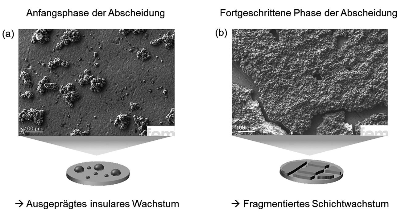 Fig. 2: SEM images of electrochemically deposited calcium layers with Ca(BH4)2 in THF: a) At low layer thicknesses, incompletely covered island structures can be seen, while b) at higher layer thicknesses, cracks and detachments occur, indicating adhesion problems and mechanical stresses. The results illustrate the central role of the process parameters for uniform and stable layer formation
The observations from the first deposition tests made it clear that more control is needed if calcium is to be deposited evenly, homogeneously and with good adhesion. Therefore, in a next step, the central process parameters were specifically investigated with the aim of systematically improving the microstructure of the layer. Table 1 summarizes the parameters that were considered in the investigations. They all have one thing in common: they have a direct effect on the structure and quality of the deposited calcium layer.
Process parameters |
Value |
|
Pre-treatment |
Chemical or mechanical |
|
Current density |
0.1 - 2.0 mA/cm2 |
|
Electrolyte movement |
0 - 500 rpm |
|
Charge quantity per area |
0.125 - 2.0 mA/cm2 |
Influence of substrate pre-treatment on the layer morphology
The pre-treatment of the substrate surface is a particularly important factor. It influences how the first calcium atoms accumulate on the surface (nucleation rate and nucleation surface density) and thus how uniform the layer becomes in the end. The experiments therefore specifically investigated how an upstream mechanical polishing process affects the layer morphology. The differences to purely chemical pre-treatment are clear. Figure 3 shows an SEM image of a calcium layer deposited on a mechanically pretreated copper substrate. The resulting layer has a thickness of about 1 µm. Compared to the chemically pretreated sample, the growth is significantly more homogeneous: the calcium structures are finer, more evenly distributed and more strongly interconnected. In addition, the layer growth partially follows the flow conditions at the interface between substrate and electrolyte. This indicates a more stable, directed nucleation process, which is influenced by the surface structure and the flow conditions.
The reason for this difference lies in the structure of the surface: the mechanical polishing process introduces additional lattice defects, so-called dislocations, in the uppermost substrate layer. These crystallographic defects act as starting points for metal growth, where calcium is preferentially deposited. The result is a more uniform and denser layer formation right from the start. The fact that this effect is not only visible in qualitative terms is also reflected in the figures: With chemically pre-treated substrates, the surface coverage is around 25 % (Fig. 2a). However, if the substrate is mechanically pre-treated, the value rises to around 50 % (Fig. 3a). This is a clear difference and a clear indication of the strong influence of the pre-treatment and thus the change in the surface on the growth of the metal layer.
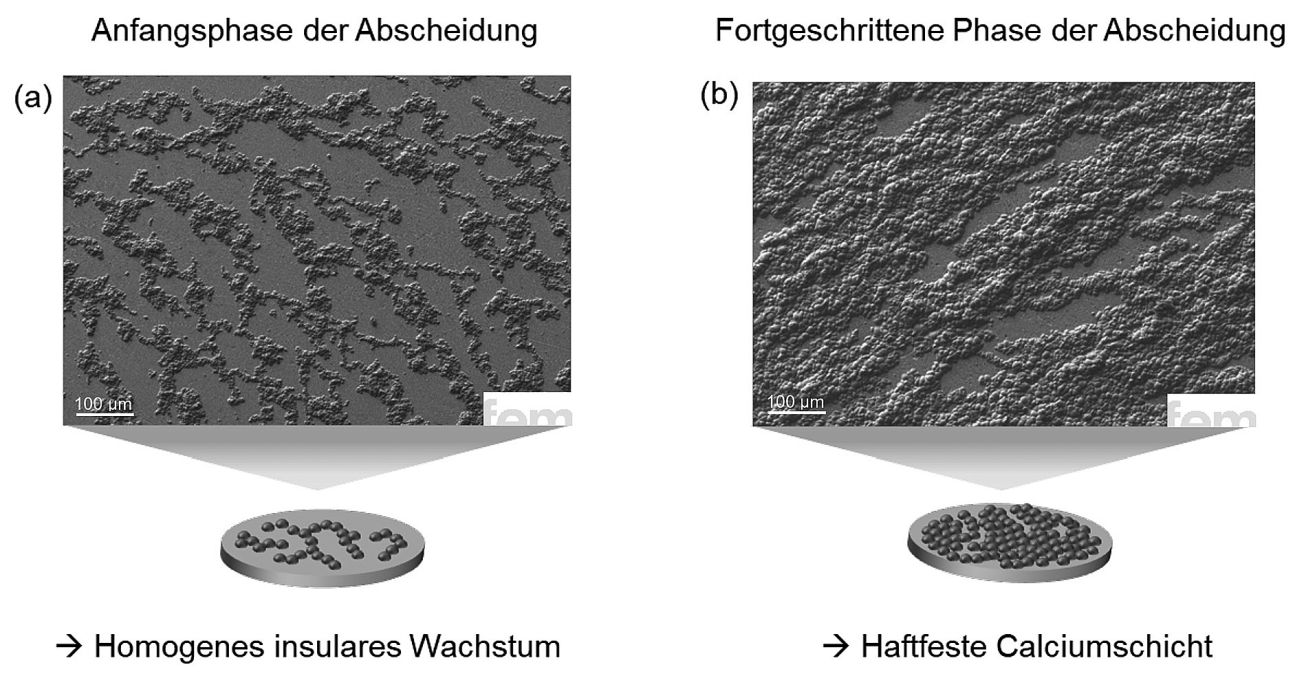 Fig. 3: SEM images of electrochemically deposited calcium layers with Ca(BH4)2 in THF: The fine, evenly distributed morphology indicates improved nucleation. Compared to chemical pretreatment, the upstream polishing process of the substrate leads to more homogeneous growth and stronger lateral cross-linking, favored by structured surfaces and electrolyte-induced flow
Current density as a control variable for nucleation and surface coverage
The extent to which the current density influences the growth of the calcium layer can be seen in the experiments with a constant amount of charge but varying current (Fig. 4). The result: the higher the current density, the greater the surface coverage. This behavior is typical for electrochemical deposition processes and can be easily explained. As the current density increases, so does the number of nucleation nuclei, i.e. the first tiny accumulations of calcium where layer growth begins, and thus also the deposition rate. The more of these nuclei are formed simultaneously, the more densely and evenly the deposited metal is distributed on the surface. However, as is so often the case, more is not automatically better. If the current density is too high, undesirable side reactions can occur. These include the decomposition of the electrolyte or the formation of unstable by-products, which are deposited in the layer structure and reduce its quality. The chemical stability of the electrolyte can also suffer, which in the long term could jeopardize not only the function of the anode, but also the cathode in later battery use. For this reason, a moderate current density of 0.5 mA/cm2 was chosen in the tests. It offers a good compromise between sufficient nucleation and surface coverage, with controlled deposition kinetics and minimal risk of disruptive side reactions. This is an important basis for creating a homogeneous, well-adhering and long-lasting calcium layer and thus a decisive building block for high-performance calcium anodes.
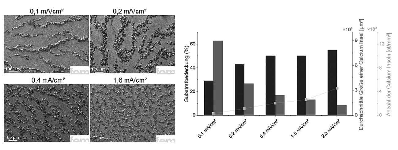 Fig. 4: Influence of current density on the morphology of deposited calcium layers: Higher current densities promote nucleation and lead to improved surface coverage. At the same time, however, the risk of electrolyte-induced side reactions increases; a balanced process window is crucial for homogeneous, stable calcium deposition
Influence of electrolyte convection on morphology and growth
In a further series of experiments, we investigated the extent to which the convection of the electrolyte, i.e. the so-called hydrodynamics, influences the growth of the calcium layer (Fig. 5). This showed that the morphology, i.e. the structure of the deposited layer, reacts clearly to changing flow conditions. The surface coverage of the substrate, on the other hand, remains largely constant. The difference between resting and stirred electrolytes is particularly striking. If the electrolyte is not stirred (0 rpm), the deposited calcium tends to form hemispherical island structures. The observed growth indicates a combination of leakage- and diffusion-controlled mechanics, as typically observed at elevated overvoltages. Under such conditions, the attached calcium atoms, so-called Ad atoms, are restricted in their mobility. As a result, crystal growth is undirected, resulting in rounded, poorly defined structures. The situation is different if the electrolyte has moderate (250 rpm) or high (500 rpm) stirring speeds. In these cases, the picture changes significantly. Instead of isolated islands, a networked growth pattern is formed in which the individual calcium clusters increasingly connect with each other. This effect can be easily explained physically. Stirring makes the so-called diffusion layer on the electrode surface thinner. This means that calcium ions reach the surface more quickly, the ion concentration remains stable and the overvoltage decreases. At the same time, the mobility of the Ad atoms increases and they can attach themselves more easily to the edges of existing islands, which promotes lateral growth. This results in flatter, more strongly cross-linked layers with a more homogeneous structure.
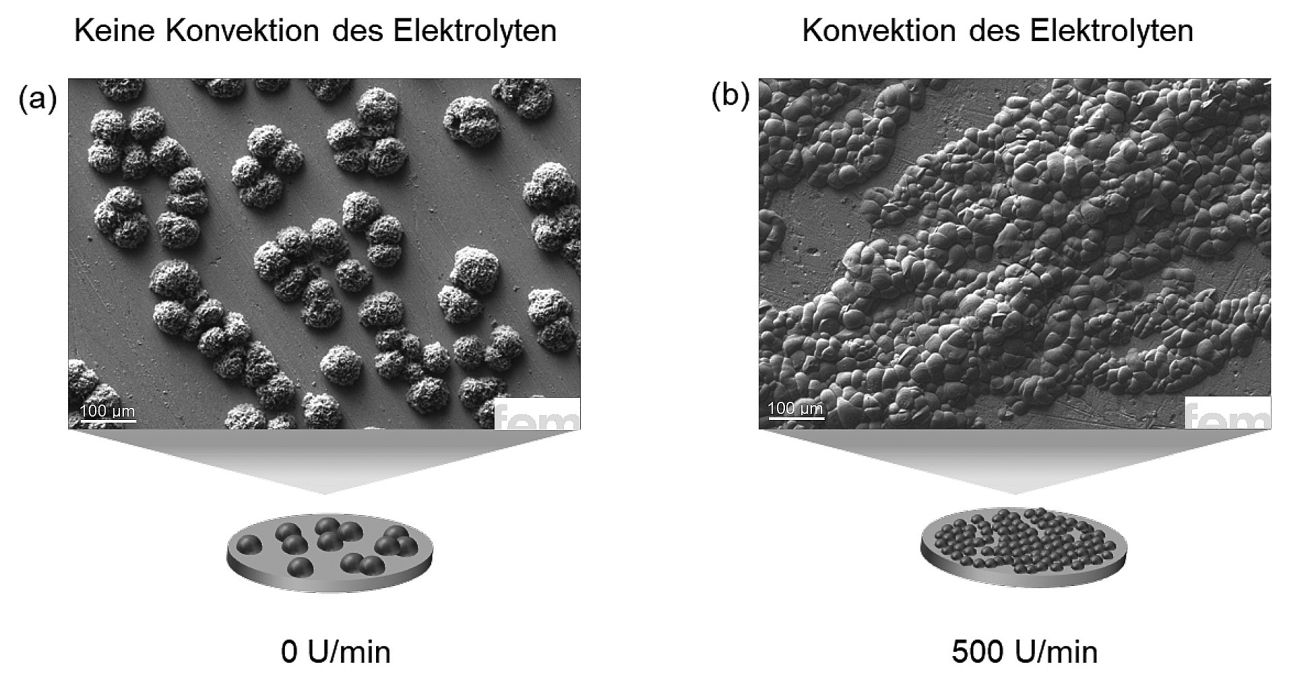 Fig. 5: Influence of hydrodynamics on calcium deposition: a) Without additional electrolyte stirring (0 rpm), hemispherical islands with non-directional growth are formed, b) at moderate (250 rpm) and high stirring speeds (500 rpm), a cross-linked growth pattern with a more homogeneous layer structure is created, due to improved ion supply and reduced overvoltage
Performance evaluation of electrodeposited Ca anodes compared to reference anodes
Based on the previous parameter studies, a calcium anode was electrodeposited under optimum conditions. The result is a well-formed layer with a thickness of around 10 µm, as confirmed by the FIB cross-section in Figure 6. The structure shows a classic picture for metallic deposits of this type: the calcium grains partially overlap, with occasional small gaps in between, typical of discontinuous grain growth. Despite these micropores, the layer has a compact overall structure and shows an even distribution of material over the surface. Even more important, however, is the energetic view of the deposition. The layer thickness and the amount of charge transferred result in a cathodic Coulomb efficiency of over 90 %. A value that impressively demonstrates the efficiency of the chosen process and is in line with comparable work from the literature. It is therefore clear that, under the right conditions, calcium can be deposited not only selectively but also efficiently.
 Fig. 6: Morphology and cross-section of an electrodeposited calcium layer under optimized process conditions. The approximately 10 µm thick layer shows typical, discontinuous grain growth with partially overlapping crystals
How well the electrodeposited calcium anode (thickness 10 µm) performs in direct comparison is shown by initial investigations with classically metallurgically produced reference samples, in particular with rolled calcium foil (thickness 100 µm). Figure 7 summarizes the results from symmetrical cell tests. This established measurement method makes it possible to analyze the charging and discharging behavior under constant conditions over several cycles, a proven approach in the early development phase of new anode materials. The result is clear: the electrodeposited anode exhibits a lower overvoltage than the reference anode in the first few cycles. This reduced polarization indicates better electrochemical reversibility and lower internal resistances in the system. The possible structural effect should also be taken into account. The effective surface area of the electrodeposited layer could be significantly larger than the nominal one, which contributes to the improved performance. The tests thus not only demonstrate the efficiency of the electrochemical deposition process, but also the high activity of the calcium layer produced. This is further proof that electroplating technology is also convincing in direct comparison with conventional production methods. Especially when it comes to controllable morphology and process-related performance advantages.
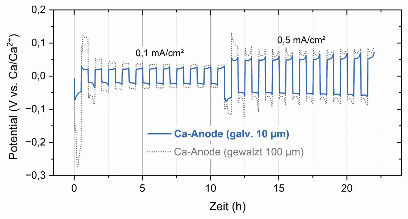 Fig. 7: Comparison of the electrodeposited calcium anode with conventionally rolled calcium foil in symmetrical cell tests. The electroplated layer shows significantly lower overvoltages, which indicates better electrochemical reversibility, lower internal resistances and higher efficiency of the deposition process
Contribution of electroplating technology to the development of more sustainable battery components
The investigations make one thing clear: if you want to work with calcium as an anode material, there is no way around customized electrolyte systems. The process can only be controlled and efficient if the chemistry of the metal and the properties of the electrolyte are precisely matched. The results of this work impressively demonstrate the potential of electrolytic deposition. It enables the production of thin, homogeneous calcium layers that not only promise a higher energy density, but also significantly reduce the safety risk in cell operation. It is precisely this combination that makes electroplating technology a key tool for the further development of calcium-based energy storage systems.
The process is anything but new or experimental. On the contrary, electroplating is an established key technology that has long since found its way into a wide range of industries. In the context of Industry 5.0, it offers a convincing combination of technical precision, resource efficiency and sustainability. It therefore makes an essential contribution to the development of future-proof battery systems and to an energy transition that not only works, but is also economically and ecologically viable.
Literature
[1] Paul, M. T. Y. & Gates, B. D. Mesoporous Platinum Prepared by Electrodeposition for Ultralow Loading Proton Exchange Membrane Fuel Cells. Sci Rep 9, 4161 (2019).
[2] Park, Y. J. et al. Electrodeposition of High-Surface-Area IrO2 Films on Ti Felt as an Efficient Catalyst for the Oxygen Evolution Reaction. Front. Chem. 8, 593272 (2020).
[3] Kiesl, C. et al. Towards Thin Calcium Metal Anodes - An Essential Component for High-Energy-Density Calcium Batteries. Nanomaterials 15, 454 (2025).
[4] Li, Z., Fuhr, O., Fichtner, M. & Zhao-Karger, Z. Towards stable and efficient electrolytes for room-temperature rechargeable calcium batteries - supplementary information. Energy Environ. Sci. 12, 3496-3501 (2019).
[5] Wang, D. et al. Plating and stripping calcium in an organic electrolyte. Nature Mater. 17, 16-20 (2018).

