
Non-destructive material testing with ultrasound is now more than 60 years old. The first attempts to use ultrasonic vibrations to detect defects in a wide variety of materials have developed into a classic testing method based on measurements that take into account all significant influencing variables. Today, ultrasonic testing, supported by the enormous advances in equipment technology, is required to produce reproducible test results within narrow limits.
In the meantime, non-destructive material testing with ultrasound is more than 60 years old. From the first attempts to detect defects in a wide variety of materials with the aid of ultrasonic vibrations, a classic testing method has developed which is based on measurements that take into account all the essential influencing variables. Today, ultrasonic testing, supported by the enormous progress in equipment technology, requires reproducible test results within narrow limits.
1 Conventional ultrasonic testing
Precise knowledge of the influencing variables in ultrasonic testing and the ability to incorporate them precisely into the testing technique are indispensable prerequisites. Not all influences are always so serious that the inspector must take them into account. In many cases, one or the other influence can be neglected without the measurement tolerances exceeding the permitted limits. This simplifies the inspection process and reduces the inspection time.
Nevertheless, the future belongs to qualified ultrasonic inspectors who carry out their tasks responsibly and constantly strive to update their knowledge to the latest state of the art.
2 Why ultrasound for non-destructive material testing?
In addition to the methods for non-destructive testing of workpiece surfaces, the dye penetrant and magnetic flux leakage methods, until the early 1950s practitioners were only familiar with radiographic testing (using X-ray equipment or radioactive isotopes) as a method for detecting internal defects.
After the Second World War, the ultrasonic method first described by Sokolov in 1935 and used by Firestone in 1940 was further developed, so that soon usable devices for ultrasonic material testing were available. The principle of ultrasonic testing is based on the fact that solid materials in particular are good conductors of sound waves.
The wave is not only reflected at the boundary surfaces of a workpiece, but also at internal defects (material separations, inclusions, etc.). The interaction of the sound wave with the material is stronger the smaller the wavelength, i.e. the higher the frequency of the wave.
3 Functionality
Detection of imperfections
The actual tool of the ultrasonic flaw detector is the probe(Fig. 1 to 4).
 Fig. 1: Vertical probe
 Fig. 2: Two-dimensional defect - vertical probe
The piezoelectric transducer, excited by an extremely short electrical discharge, emits an ultrasonic pulse. On the other hand, the same transducer generates an electrical signal when it starts to vibrate due to an incoming sound signal. The probe is coupled to the workpiece surface with a liquid or coupling paste so that the sound waves can be transmitted from the probe to the workpiece.
") Fig. 3: Angle probe (section)
Fig. 3: Angle probe (section)
 Fig. 4: Surface defect - angle probe
The inspector then scans the workpiece, i.e. he moves the probe evenly back and forth on the surface. In doing so, he looks out for signals that could be caused by reflections from internal imperfections or, as in the picture below, from a plane-parallel rear wall.
Each probe has a specific directional effect, i.e. the ultrasonic waves only detect a specific section of the test piece. The area effective for ultrasonic testing is called the sound beam, which is characteristic of the probe used and the material in which the sound waves propagate. A sound beam can be roughly divided into a convergent (focusing) area, the near field, and a divergent (diverging) area, the far field.
The length N of the near field (near field length) and the opening or divergence angle depend on the diameter of the transducer, its frequency and the speed of sound of the propagation medium. The center beam is referred to as the acoustic axis. When selecting a transducer to solve a specific test task, the shape of the sound beam used naturally plays an important role. However, it is often sufficient to simply draw the acoustic axis to show what the solution to a test task looks like.
 Fig. 5: Rear wall echo at Skt. 8
") Fig. 6: Acoustic beam (Source Figs. 1-6: Fundamentals of ultrasonic testing Special Edition KK 218)
Fig. 6: Acoustic beam (Source Figs. 1-6: Fundamentals of ultrasonic testing Special Edition KK 218)
4 types of waves - interesting for ultrasonic testing
Most standard vertical probes transmit and receive longitudinal waves (pressure waves). They are characterized by the fact that the vibrations propagate in the form of compressions and rarefactions in all materials (gases, liquids and solids). Vertical probes are available in a wide range of sizes with frequencies from approx. 0.5 MHz to 25 Mhz. They can be used to achieve ranges of up to 10 m and more, allowing even the largest workpieces to be tested. For technical reasons, most standard probes transmit and receive transverse waves or shear waves. In a transverse wave, the atoms (molecules) oscillate perpendicular to the direction of propagation of the wave, as the excitation is caused by shear forces (forces directed transverse to the direction of propagation). Transverse waves also have the property that they can only occur in solid substances, i.e. never in liquids and gases, as these have no shear modulus, i.e. no shear forces can act here either. Furthermore, they propagate much more slowly than longitudinal waves in the same material.
5 The phased array technique
The principle of phased array technology
A conventional transducer is compared with an array. In this array, 64 individual elements are combined. Each of the individual elements represents a separate ultrasonic transducer with its own defined size.
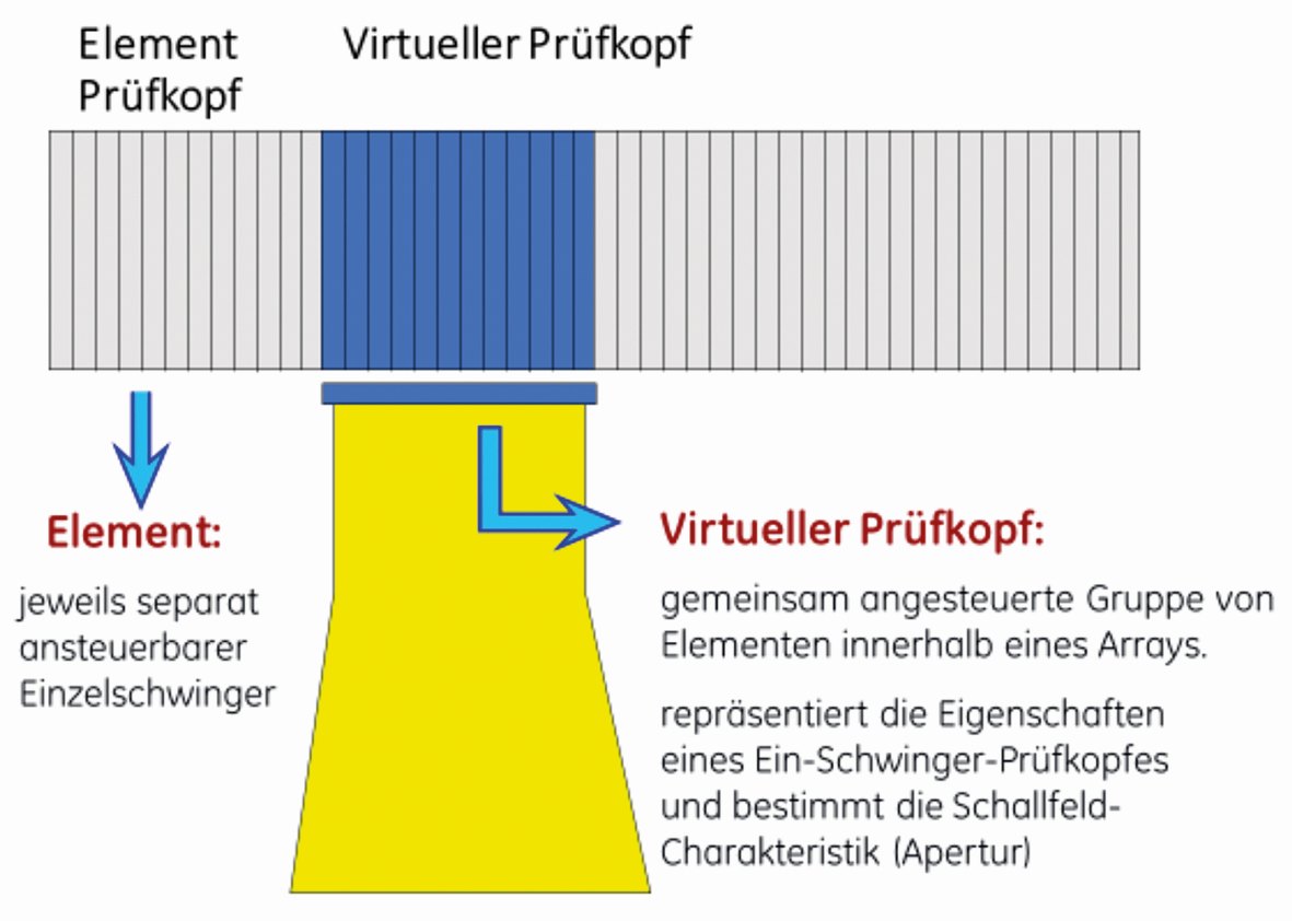
 Fig. 8 and 9: Virtual transducers control individual groups within the array one after the other
The individual elements of the array are controlled at different times. It is also possible to control individual groups within an array one after the other. The total size of these groups represents the size of the individual transducer. This is referred to as virtual individual oscillators in the array.
Single-transducer probes have a fixed focus and a fixed nominal angle. If several focal depths and several beam angles are required for a test, different probes must be used for ultrasonic testing.
Phased array testing allows the user to change the angle and focus in a probe as required by the testing task. In a phased array probe with a linear arrangement of the individual elements, up to 128 elements are generally used.
This has the advantage that certain areas can be tested not by moving the probe, as is the case with conventional testing technology, but by moving the sound field along the length of the probe. The probe remains in one position.
 Fig. 10: A separate probe is required for each angle and each focus
 Fig. 11: Control of focus and angle
Figure 14 on the left shows the conventional sound path of a single-transducer probe. The image of the transit time is represented by a so-called A-scan. The reflection of the cross bore is indicated by a pick in the A-scan.
The figure on the right shows a phased array probe with x elements. Due to the different timing of the individual elements or the combination of any number of elements programmed by an aperture, any number of virtual individual transducers can be arranged in sequence across the entire width of the probe.
 Fig. 12: Phased array sound field formation uses up to 128 elements
 Fig. 13: Conventional testing is carried out by moving the probe; with phased array testing, the sound field is shifted
The control sequence of these transducers results in the sound field also moving in the X direction from the start of the probe to the end of the probe.
The sound field can now be moved over a defined length above the test object in a static position of the probe. Figure 14 shows the representation of all 3 transverse bores at different depths/running times and at different positions in the component.
 Fig. 14: Linear illustration.
left conventional, right with phase array probe
 Fig. 15: Conventional testing technique with fixed angle
Fig. 15 shows the image with conventional testing technology (A-scan) at the top with a fixed angle. Only one reflector can be displayed in the A-scan. If the test head is moved backwards, only the lower reflector can be displayed in the A-scan.
In the lower image, both holes can be displayed in the sector image with the same probe position. The usable angle range extends from approx. 35° to 75°.
6 Test coverage using the example of a weld seam
The positioning of the probe is calculated up to the center of the weld seam (dimension A). During the test, this dimension (in the example, Fig. 16, 36 mm) remains constant.
 Fig. 16: Weld seam with heat-affected zone
> Fig. 17: Minimum step distance
This dimension depends on the thickness of the test specimen and the leading wedge dimensions of the test probe.
With the large number of individual beam angles, in this case from 35° to 70° (70 so-called beam angles), the following figures 18 to 24 consider individual angles and thus the coverage of the weld seam volume. In detail, the angle ranges 35°, 45°, 50°, 55°, 60°, 65°, 70° are shown. Typical weld seam defects could be flank bonding defects, root defects, pores or central defects and defects in the cover layer(Fig. 26). Defects are shown as ellipses where the lateral extent corresponds to the size of the sound beam at the reflection surface and the axial extent corresponds to the echo width(Fig. 27 and 28).
The defect indications that the user has recorded with the constant probe position to the weld seam center are interpreted(Fig. 29 and 30). The advantages of this method in ultrasonic testing are obvious:
- Fast reflector detection
- Very good interpretation of indications due to the B-scan display
- Detection of inspection areas with only one probe, which previously required a probe change.
7 application examples
Tandem technology
Tandem testing is used in accordance with the standard to detect vertically oriented discontinuity indications from a material thickness of 90 mm. The test zones are determined depending on the wall thickness of the test object.
For this purpose, 2 probes are used for conventional ultrasonic testing, which have an angle of incidence of 45°.
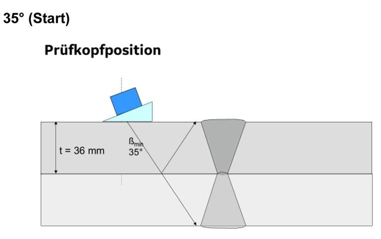
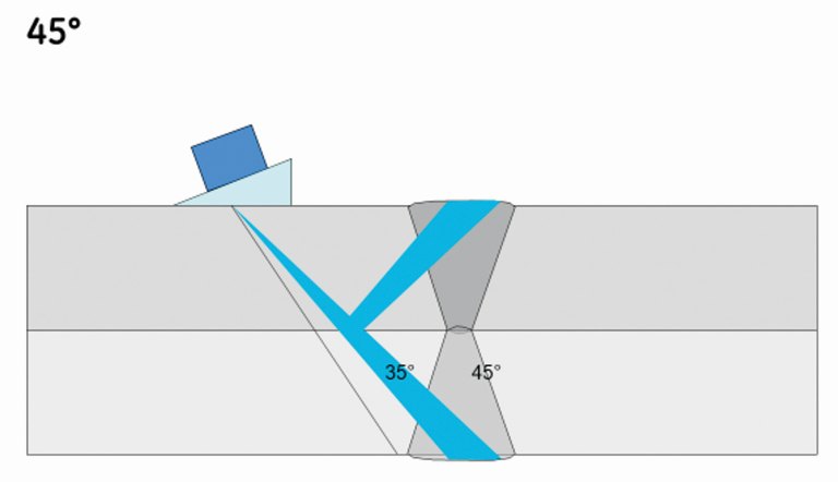
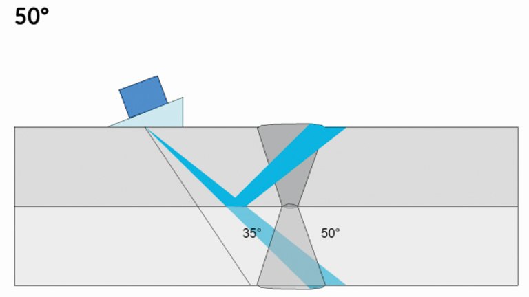


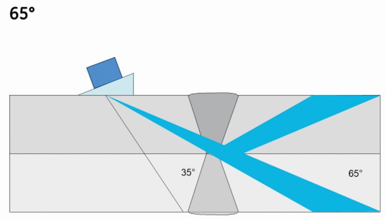
 Fig. 18-24: Testing in different angle ranges between 35 and 70°
The probes are attached to a ruler so that the distance set for the individual test zones can be kept constant. Figures31-33 below show the individual test zones, each with a constant distance between the probes.
 Fig. 25: The entire weld seam cross-section is tested from a fixed position of the test head
 Fig. 26: The weld seam defects are shown in red
 Fig. 27: Various defect displays
 Fig. 28: Elliptical representation of the defects in the tested sector
 Fig. 29: Constant probe position...
 Fig. 30: ...aligned towards the center of the weld seam
Test task
A friction weld butt weld of a hydraulic cylinder, in which defects primarily occur in a vertically oriented direction, is to be tested for vertically oriented bonding defects. Angle scanning with only one conventional probe would not lead to a meaningful result due to the lack of reflections from the defect.
The positioning of a conventional vertical probe to detect these defects would be necessary at a distance of 2000 mm for geometric reasons.
Due to the existing geometry, no reliable echo height evaluation of the supposed defect indications could be made at this distance.
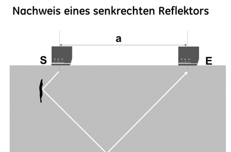
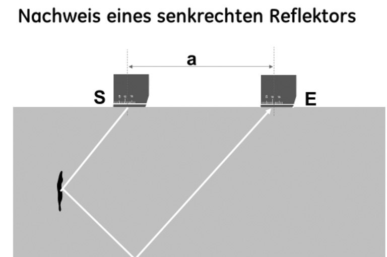
 Fig. 31-33: Three examples of a vertical reflector with the tandem technique
In this example, the aperture was programmed on a phased array probe with 64 elements so that in the first step, elements 1 to 10 were transmitted. Elements 55 to 64 were set to receive. In the subsequent steps, elements 2 to 11 transmitted and elements 54 to 63 received the signal. The further steps are repeated up to elements 28 to 37, which first transmit and then receive, as shown in Figure 34.
 Fig. 34: Repetition of the test steps with transmit and receive
 Fig. 35: Probe guidance parallel to the weld seam with C-scan
The test depth is slightly more than half the diameter of the test object. In order to cover the entire volume, the test head is guided 180° along the outer surface of the cylinder parallel to the weld seam(Fig. 35).
8 Summary
Phased array technology offers significant advantages over conventional ultrasonic testing. The decisive factors for the use of PA technology are the material and testing costs, given the much higher time required for conventional testing.
The automated phased array technology requires validation by the client before each test. This means that the requirements set out in the specifications are met before a system is commissioned.
With manual phased array testing (PAUT), the aim is to follow European standards and regulations as far as possible. Not all of these have yet been implemented. As a result, the European product standards and implementation standards for conventional ultrasonic testing often apply. At present, PAUT is primarily used in companies that use ultrasonic testing for their own quality assurance. In most cases, PAUT is used for specific applications.
The company
GE Inspection Technologies GmbH, with its German headquarters in Hürth near Cologne, manufactures ultrasonic systems and portable ultrasonic devices. The product range includes approx. 5000 standard ultrasonic probes, but of course also probes that are manufactured to customer specifications. The Hürth site also includes a service center for ultrasonic devices and endoscopes.
There are also sites in Germany in Hanover, where X-ray CT systems for industry are developed and manufactured, and in Ahrensburg, where both fluoroscopy systems and portable X-ray systems for industry are manufactured.
