The working group led by Prof. Dr. Timo Sörgel at Aalen University has been researching the use of electroplating processes to improve today's electrodes for lithium batteries since 2013. A new process was developed, which the working group calls "composite electroforming". The process and the composite film material produced in the process were registered as a European patent by Aalen University and granted in Germany, France and the UK in January 2019. The world's first pilot plant for the innovative combination of dispersion deposition and film electroforming was put into operation in Aalen in December.
Since 2013, Prof. Dr. Timo Sörgel's research group at Aalen University has been researching the use of electroplating processes to improve today's electrodes for lithium batteries. A new process has been developed, which the working group calls "composite electroforming". The process as well as the composite film material produced in the process was applied for as a European patent by the Aalen University of Applied Sciences and granted in Germany, France and Great Britain in January 2019. The world's first pilot plant for the innovative combination of dispersion deposition and foil electroforming was commissioned in Aalen in December.
Introduction
 Fig. 1: Schematic representation of the one-step process of composite electroformingInour last detailed article on the production of an innovative cathode for lithium/sulphur batteries using electroforming processes [1], the new concept of combining dispersion deposition [2] and electroforming was described in detail. The combined process - called composite electroforming - was patented by Aalen University in Germany, France and Great Britain [3]. With the help of composite electroforming, self-supporting composite films are produced in just one process step. As the surface of the cylinder serving as the substrate material is molded during electroforming, the resulting composite film has a smooth, dispersoid-free underside. The absence of dispersoids in the first micrometers of the electroformed layer is explained by the "riding" effect [4]. The particle-free base layer is very advantageous for film stability and thus for further processing. The upper side of the film, which faces the electrolyte, grows as a dispersion layer. It is possible to create a structured surface by selecting and, if necessary, functionalizing the dispersoids and adjusting the deposition parameters [5, 6]. A schematic representation of the process is shown in Figure 1.
While the first experiments in the working group were still carried out in beakers with static substrates, the transition to a rotating substrate already brought about decisive improvements in terms of homogeneity and particle incorporation rate of the films [1, 7, 8]. This method was then further optimized.
Improved test setups
 Fig. 2: Evolution of the test setups at Aalen University, left: Steel cylinder with diameter d = 22 mm, center: titanium cylinder with d = 68 mm in batch operation, right: titanium cylinder with d = 68 mm in continuous film productionDisadvantagesof the originally used cylinder with a diameter of only 22 mm were the small coating area and the pronounced edge effect. The change from the small steel cylinder to a significantly larger titanium cylinder (diameter 68 mm) already brought decisive improvements. In addition, the coated area per test was increased from around 25 cm2 to 111 cm2. This set-up was used to prove the feasibility of continuous composite electroforming - the production of continuous films. Continuous films can be produced if, after a starting phase in which a sufficiently stable layer is deposited on the cylinder, the resulting layer is cut perpendicular to the radius and then lifted off on one side. The end of the film is continuously peeled off. In continuous operation, there is therefore exactly one revolution of the cylinder to produce the stable film. The evolution of the test set-up is shown in Figure 2.
Pilot plant
As part of a validation project, the world's first pilot plant for continuous composite electroforming was put into operation at Aalen University at the end of 2019. The system was designed and planned together with the company Elanis Ivanka Majdacic, which also implemented the design and construction. The heart of the system is the separator tank with a titanium roller, which has a diameter and a cylinder height of 30 cm each. The resulting film is transported by means of a roller system and a vacuum conveyor belt. A quadruple cascade rinse with integrated hot rinse in the last rinsing stage and an infrared dryer complete the main components. Figure 3 shows the complete system in the electroplating laboratory at Aalen University.
The electrolyte volume comprises a total of approx. 290 liters, which are indirectly heated to a temperature of 60 °C. Great importance was attached to flexibility in the pilot plant in order to be able to evaluate as many different parameters as possible.
 Fig. 3: Photo of the world's first pilot plant for composite electroforming in the electroplating laboratory at Aalen UniversityVariation optionsinclude
- separate control of the three anodes using different rectifiers
- changing the roller position and the anode positions
- infinitely variable control of the rotation speed of the roller in the range from 0 to 80 cm/min
- setting the optimum convection by using two circulation pumps and three different, swiveling inflow pipes.
The homogeneous distribution of the dispersoids in the electrolyte is ensured by an agitator in conjunction with a circulation pump circuit.
Electrolyte chemistry
While the proof-of-concept of the new method was still carried out with copper electrolytes [9], it quickly became apparent that nickel offers decisive advantages as a matrix metal, both in terms of electroforming and for later battery applications. While the first tests were carried out with a classic Watt's nickel electrolyte, the internal stresses that occurred led to a switch to a nickel sulphamate electrolyte.
Currently, a nickel sulphamate electrolyte is used in the pilot plant in combination with insoluble anodes. The preparation is carried out with a nickel ion concentration of 110 g/L from nickel sulphamate concentrate (180 g/L; technically pure; BRW Elektrochemie GmbH & Co. KG, Balve) and a boric acid content of 30 g/L (technically pure; BRW Elektrochemie GmbH & Co. KG, Balve).
On the anode side, a platinized titanium expanded metal anode and two closed, platinized titanium anodes are used. The anodes are curved in a radius adapted to the roller. The distance to the roller can be adjusted between 30 mm and 120 mm.
During the process, nickel hydroxycarbonate (39 % nickel content, technically pure; BRW Elektrochemie GmbH & Co. KG, Balve) is used as a nickel supplier. At the same time, the addition of the basic nickel salt compensates for the reduction in pH value as a result of oxygen development at the anode. The dosing is controlled automatically depending on the pH value.
To produce the dispersion electrolyte, the nickel sulphamate electrolyte is first prepared directly in the system, heated and circulated. The dispersoids are then added directly to the electrolyte in the system.
Dispersoids
As already described in previous publications [9, 10], the use of polythiophene-functionalized sulphur particles has proven itself as the active material for this process. While sulphur is hydrophobic and floats in aqueous electrolytes, polythiophene-functionalized sulphur can be dispersed very well and incorporated into the dispersion layer.
The chemical functionalization of the sulfur particles is based on a synthesis described by Wu et al [11] and has already been successfully carried out by us on a 550 g scale. The battery active material obtained in this way is preferably used in concentrations of 10 g of particles per 1 L of nickel sulphamate electrolyte. Particle concentrations of approx. 2 g/L were used for the first series of tests on the pilot plant.
Results
So far, currents of between 10 and 150 A per anode, corresponding to a total current of 30 to 450 A and a cathodic current density of approx. 1 to 15 A/dm2 have been set on the pilot plant. The rotation speed of the roller was varied within a range of 4 to 25 cm/min, i.e. a full rotation was achieved after 3 to 24 minutes.
The dwell time of the film in the electrolyte is controlled by varying the rotational speed, i.e. the faster the rotational speed at a constant current density, the shorter the deposition time and the thinner the composite galvanoformed dispersion film.
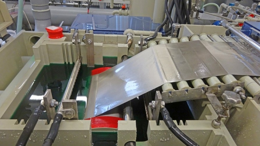
Figure 4 (above) shows the electrode film during its formation in the pilot plant.
 Fig. 5: Left: Composite galvanoformed electrode film after rinsing and drying at the end of the pilot plant; right: scanning electron micrograph of a composite galvanoformed electrode film with a highly structured surface produced on the pilot plantIthas already been possible to successfully produce around two hundred meters of the innovative films with a width of 30 cm at speeds of up to 25 cm/min. As already described in the experiments in the beaker, the dispersion layers grow with a strong structure. A photo and a scanning electron micrograph of an electrode film produced on the pilot plant are shown in Figure 5.
Due to the strong structuring and the open, coral reef-like structure, the integrated active material is very easily accessible for the battery electrolyte when later used in battery test cells. This and the improved conductive paths due to the direct connection to the matrix metal enable faster charging and discharging compared to compact, compressed electrode layers.
Application
Due to their high specific energy, lithium/sulphur batteries are considered a promising storage technology for realizing the energy transition. Conventional lithium/sulphur cells consist of a sulphur composite cathode, which is a mixture of the active material sulphur, a conductive additive such as carbon black and a polymer binder [12, 13]. As an alternative to the classic production method, the innovative composite electroforming process is used in Aalen. Figure 6 shows scanning electron micrographs of cross-sections of a state-of-the-art cathode and a composite electroformed cathode.
 mit einer kompositgalvanogeformten Kathode (rechts)") Fig. 6: Comparison of a classic state-of-the-art composite cathode (left) with a composite electroformed cathode (right)
Fig. 6: Comparison of a classic state-of-the-art composite cathode (left) with a composite electroformed cathode (right)
With state-of-the-art cathode materials, a compromise between the additives - binder and carbon/conductive carbon black - is always necessary. The addition of binder increases the mechanical stability of the electrode, but at the same time increases the grain boundary resistance, which has a detrimental effect on conductivity. By increasing the proportion of conductive additives such as carbon, the electrical conductivity increases, but at the same time the mechanical stability of the electrode is reduced.
The process developed at Aalen University allows synergetic optimization for the first time, as the mechanical AND electrical contacting of the active material is carried out by a single metal. In addition, there are clear advantages with regard to the current collector function. In the case of composite electroforming, there is no material separation of current collector and electrode material. As the current collector is produced in situ and then connected directly to the active material, there is no risk of passivation at the metal/active material phase boundary.
Thestructure of the composite galvano-molded electrodes offers the following advantages:
- improved battery properties in terms of charge and energy density, energy efficiency, cycle and rate stability (fast charging capability)
- potential savings by dispensing with binders and electrically conductive filler particles
- Synergistic optimization of the mechanical and electrical contacting of the active material particles
- Can be used in Li/sulphur and Li-ion cells, both on the cathode and anode side
- Single-stage manufacturing process through combined dispersion deposition and electroforming
- More environmentally friendly production process due to the production of the films from long-life aqueous electrolytes instead of the toxic organic solvents used in the state of the art, which have to be evaporated after the application process
- Simplification of recycling processes at the end of the product life cycle by reducing the number of cathode components and simplifying separability
Pouch cells are constructed and electrochemically characterized to evaluate the battery characteristics. Electrode sheets (see Fig. 7, left), which represent the cathode, are punched out of the films produced for this purpose. Lithium foil is used as the anode, which is applied to a copper arrester foil. A polymer separator (usually polyolefin) reliably separates the cathode from the anode chamber and thus prevents an internal short circuit. A mixture of 1,2-dimethoxyethane with 1,3-dioxolane (1:1, vol:vol) as well as 0.75 mol/L lithium nitrate and 1 mol/L lithium bis(trifluoromethanesulfonyl)imide (LiTFSI) serves as the battery electrolyte.
, Pouchzellfolie, Batterieelektrolyt") Fig. 7: Components for the construction of pouch cells. From left to right: die-cut composite galvanoformed cathode with nickel discharge tab, copper foil as anodic current collector with nickel discharge tab, lithium foil applied to the copper current collector, separator (polyolefin), pouch cell foil, battery electrolyte.
Fig. 7: Components for the construction of pouch cells. From left to right: die-cut composite galvanoformed cathode with nickel discharge tab, copper foil as anodic current collector with nickel discharge tab, lithium foil applied to the copper current collector, separator (polyolefin), pouch cell foil, battery electrolyte.
Following the first successful tests, pouch cell construction will be intensified in the coming months. Electrochemical battery tests such as electrical impedance measurements, cyclovoltammetry and cyclizations will follow shortly.
Summary and outlook
Aalen University has been conducting intensive research into the innovative idea of combining dispersion deposition and electroforming - known as composite electroforming - since 2013. The world's first pilot plant was successfully put into operation at the end of 2019. It has already been possible to produce around two hundred meters of the innovative battery electrode foils at speeds of up to 25 cm/min. The flexible system allows numerous variation options for the evaluation of a broad parameter window.
In the next step, the deposition parameters are to be examined in detail and the installation rate of active material optimized. Battery tests on pouch cells to determine the cell characteristics are in preparation.
Thanks to
We would like to thank the German Federal Ministry of Education and Research BMBF for funding this work as part of the GoForE project (funding reference 03VP05120). Special thanks go to our equipment manufacturer, the company ELANIS Ivanka Majdacic, and to Mr. Michael Schüle for his research master's thesis in this field.
Literature
[1] C. Erhardt; S. Meinhard; Sörgel: Galvanotechnik 106, 2015, 2396
[2] T. Sörgel; J. Meyer: WoMag 9, 2, 2013, 24-33
[3] T. Sörgel; S. Meinhard; Sörgel: EP 3 114 721 B1, 2015
[4] L. Stappers; J. Fransaer: J. Electrochem. Soc. 154, 2007, D598
[5] R. Winand: Hydrometallurgy 29, 1992, 567
[6] R. Bazzard; P.J. Boden: Trans. Inst. Met. Finish., 1972, 63
[7] C. Erhardt; Sörgel; S. Meinhard; T. Sörgel: Yearbook Surface Technology 2015, 198
[8] T. Sörgel: ZVO Report 2019, 46
[9] C. Ehrhardt; Sörgel; S. Meinhard; T. Sörgel; J. Power Sources, 296, 2015, 70
[10] Sörgel; O. Kesten; A. Wengel; T. Sörgel: Energy Storage Mater, 10, 2018, 223
[11] F. Wu; J. Chen; R. Chen; S. Wu; L. Li; S. Chen; T. Zhao: J. Phys. Chem. C, 115, 2011, 6057
[12] A. Manthiram; Y. Fu; S.-H. Chung; C. Zu; Y.-S. Su: Chem. rev, 114, 2014, 11751
[13] H.-J. Peng; J.-Q. Huang; X.-B. Cheng; Q. Zhang: Adv. Energy Mater. 7, 2017, 1700260
