Shearing has long since ceased to be a punishment: today, a shaved head is a fashionable thing, which became a trademark with Yul Brynner [3]. On the other hand, whether different combs were used for shearing sheep also seems dubious, as the traditional shears are shown differently in depictions.
Whether this basic idea can be transferred to the production of surface-mounted PCBs is a question that some process engineers who have to deal with a large number of different assemblies are asking themselves. After all, it's a completely different story when you send the same product down the line thousands of times a day or are faced with a jumble of assemblies that are only produced in small batches.
The desire for a uniform thermal profile for the reflow system is not just the result of laziness, but would also have a positive effect on the productivity of the line.
Depending on the reflow system, the changeover can take quite a long time. In addition to the waiting time until the newly set profile has stabilized again, it should also be verified before leaving expensive assemblies to their fate in a hot environment. Until this has hopefully been successfully completed, production on this line comes to a standstill.
The further apart the settings are, the longer the wait. This can add up to 20 minutes and then another 10 minutes or so for verification. How often can you afford a production stoppage of 30 minutes in one shift?
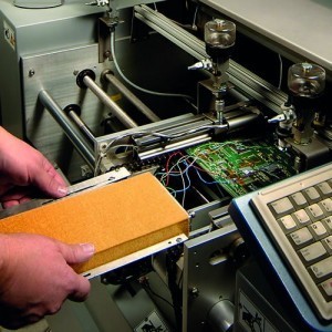
 Fig. 2: Side rider on width-adjustable profiler support and assembly with thermal sensorEvenwith a changeover, the costs are easy to calculate. Assuming that a machine hour costs € 15,000 (or more, and not € 40 as some accountants assume - it's not just electricity and nitrogen, but hundreds of products that are not manufactured and therefore not sold), then you're looking at € 7,500 for half an hour - without including the work involved.
First of all, it should be mentioned that there are different reflow methods. Convection systems are now the most popular, followed at some distance by condensation soldering, while infrared-based radiation systems have become rare. Particularly in the case of gas reflow systems, there are a great many designs ranging from just a few modules to machines that can hardly be accommodated in a normal room, which not only has an impact on profiling but also on throughput.
With infrared, errors in profiling and operation are hardly forgiven, while condensation usually requires only minor changes as long as the assemblies are thermally similar.
With gas systems, it is often possible to put together groups that can each be soldered with one profile, which is not ideal but represents an acceptable compromise.
In such discussions at conferences and in internet forums, it is usually deliberately ignored that the 'ideal' thermal profile for an assembly is extremely difficult to establish. There is no recipe for this and reference is always made to the paste, the components, the PCB, the distribution of the copper, etc.
But if you take a closer look at the paste manufacturer's specifications for their mixture or investigate the components, you will usually be very disappointed, because they are also just fiddling around with a stick in the fog and their temperature ranges or times are often so narrow that they cannot be adhered to or so wide that they are meaningless.
Even the attachment of thermal sensors to the assembly is a source of controversy. On the one hand, there is the method - with adhesive, with adhesive tape, soldering, clamping, pressing on? - On the other hand, the arrangement - at the edge, in the middle, under components, on components ??? - that the process engineer's face slowly turns red with holy rage.
With some of these methods, the assemblies are then no longer suitable for sale and end up as scrap, which can be a real financial burden if the products are expensive. So the 'golden assembly' is recommended, but after ten or fifteen excursions at the latest, it no longer delivers reasonable results and therefore only slightly reduces costs.
Since you can't find the 'ideal' setting for every product anyway or have it available, you can also cheat a little. Instead of chasing after this chimera, a pragmatic approach is taken.
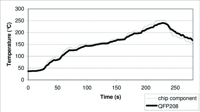
Depending on the most sensitive components, a temperature increase of between 2 and 4 K/second is selected. Most component manufacturers are satisfied with this. A so-called 'plateau' is avoided because the new pastes, or more precisely the flux activators mixed into them, do not survive this. The situation is somewhat more favorable with a properly inert atmosphere (let's say < 500 ppm residual oxygen) if, for example, the grape effect ('graping' in good new German) is to be avoided.
 Fig. 3: Thermal profile with a temperature rise of approx. 1.1 K/second and a maximum temperature of 240 °C
The maximum temperature is critical, on the one hand because of the components, on the other hand because of the flux used and then also because of the quality of the soldering. If the process engineer believes the salesman or the data sheet, he is dreaming in color, because the eutectic alloy mentioned is definitely not present everywhere on the PCB. In addition, metals are alloyed that shift the melting point further upwards. So at least 10, better perhaps 15 K above the promised melting point of the alloy may work, but is still close, but is chosen because you have to be guided by the components.
This temperature must be maintained until all solder joints have reached it. This ensures that 'soldering' has been completed.
Now you are satisfied and lower the temperature as you have raised it.
On 'related' assemblies, i.e. those where you suspect similar thermal mass and whose components have comparable specifications, you should try out whether the profile also produces acceptable results for them. If so, you can check them off under these settings and there is no need to change the parameters on the machine.
However, this requires a somewhat more long-term logistical measure. In production, the products listed under this process must be manufactured one after the other, otherwise the effort will not have been worthwhile.
About the person
Prof. Rahn is a globally active consultant in the field of joining technology. His new book on 'Special Reflow Processes' was recently published by Leuze Verlag. He can be contacted at
Literature:
C. Zheng: Why Thermal Characteristics of Components are Important for Reflow Soldering, Seeed Fusion Service, 2019
P. Austen: Thermal Profiling: Sensitive Component Degradation, I-Connect-007
L.G. Pymento et al: Process Development with Temperature Sensitive Components in Server Applications, IBM, January 2008
N.N.: SMT Reflow Soldering Temperature Curve, NexPCB, Nov 19, 2018
E. Briggs; R.C. Lasky: Best Practices Reflow Profling for Lead-Free SMT Assembly, SMTA China (Shanghai) 2009
J.R. Wilcox et al: Managing Temperature Sensitive Components in Pb-free (Power) Assemblies, IBM Corporation, 2011
References:
[1] Probably from ancient Germanic criminal law: criminals' heads were shaved as a punishment; possibly also influenced by sheep shearing
[2] Detail from Les Très Riches Heures du du duc de Berry, Juillet' in the Musée Condé, Chantilly
[3] Yuliy Borisovich Briner; (Russian: Юлий Борисович Бринер, 1920-1985)


