Base materials for printed circuit boards are also subject to a product life cycle. Depending on the application, they may be flash in the pan, for example if they were developed specifically for a series of smartphones - or they may have the potential to become long-livers.
In most cases, it is only in retrospect that we know why a development was not destined to have a long life. When switching to lead-free soldering, the first approach was to simply offer standard dicy laminates using the same resin system with a higher Tg. Almost every base material manufacturer had a Tg 150 °C and Tg 170 °C in their portfolio, at Nan Ya it was the NP-150 and NP-170. It became clear relatively quickly that it was not the Tg, but the thermal resistance of the resin system, which is not related to the higher glass transition temperature, that prevents failures during soldering. The high-Tg material even exhibited a lower decomposition temperature than the mid-Tg variant and was the first to be removed from the program.
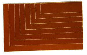 Fig. 1: Layer structure H/H 1.55 mm with 8 sheets of prepreg NP-175FBHBThecuring system influences the decomposition temperature of a base material. Sufficient thermal stability is achieved by phenol-novolak curing, so that several lead-free soldering processes are possible without delamination. In 2005, the keyword 'Lead Free FR4' was introduced for the first time with the IPC-4101B and the decomposition temperature, z-axis expansion and time to delamination were specified as reliability criteria.
For the IPC-4101 Tg classes at least 110 °C / 150 °C / 170 °C there is a specification sheet for types with (#101, #99, #126) and without (#121, #124, #129) inorganic filler(s). From the early days of lead-free soldering, Tg 150 °C had established itself as the starting point, while Nan Ya offered a choice of NP-155, NP-155F, NP-175 and NP-175F. The last number 5 indicated that this was a thermally stable PN resin system, while F in the type designation indicated the fillers it contained.
What distinguishes real long runners
The unfilled variants were discontinued after a very short time. The market's verdict was very clear when it came to the trade-off between slightly lower drill wear without fillers and lower z-axis expansion and therefore less stress on the through-hole plating sleeve. The filled types NP-155F and NP-175F are real long runners.
|
Property |
Unit |
NPG-150N |
NPG-151 |
|
|
Tg |
°C |
150(DSC) |
155(DSC) |
|
|
Td |
5%weightloss |
°C |
370 |
385 |
|
T288 |
min |
10 |
> 60 |
|
|
Max. Grouting cycles |
4 |
7 |
||
|
E-modulus 12 x 1037 |
@ 50 °C |
GPa |
9-10 |
11-12 |
|
@ 250 °C |
3-4 |
5-6 |
||
|
CTE z 12 x 1037 |
α1 |
ppm/K |
50-60 |
30-40 |
|
α2 |
270-280 |
220-230 |
||
|
TE(50 °C - 260 °C) |
% |
3,45 |
2,80 |
|
|
Moisture absorption |
PCT(30 min) |
% |
0,22-0,24 |
0,13-0,15 |
|
PCT(120 min) |
0,40-0,42 |
0,26-0,28 |
||
|
Dk |
RC 70 % @ 1GHz |
4,00 |
4,00 |
|
|
Df |
0,015 |
0,015 |
||
But what leads to a base material type that has no real weak points being removed from the manufacturer's portfolio in the medium term? Specifically, we are talking about NPG-150N, an FR-4.1 (Low Halogen Content) with a low CTE z, ideally suited for lead-free soldering and in no way affected by the discussion about TBBPA in brominated resin systems due to its flame-retardant mechanism.
In this case, it is the successor NPG-151, which has been successfully established on the market in Asia for years, not only in multilayers for smartphones, but also in PCBs for e-mobility, where high voltages require maximum CAF resistance. The requirements for the base material have grown over the years due to technological developments. As a more recent development, NPG-151 naturally fulfills these requirements better than NPG-150N, which had completely different criteria when it was introduced to the market.
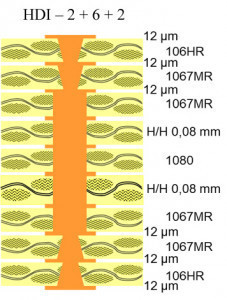
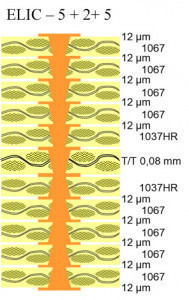
Halogen-free base material has been the domain of PCBs for smartphones and network technology for two decades. In the former, the trend towards ever greater functionality, accompanied by component miniaturization, is achieved by printed circuit boards in which routing is made possible by sequential pressing, with a large number of vias connecting only two layers at a time. One PCB design for maximum functional density is ELIC - Every Layer Interconnect; the number of pressing steps increases accordingly with the number of layers.
This is where the first requirement comes into play, which has necessitated further development of the resin system. It must be suitable for a large number of pressing cycles. Two material parameters are decisive for this: the decomposition temperature Td and the time until delamination at 288 °C, i.e. T288.
The very high temperature values for the decomposition temperature should not be misleading. It has been introduced for comparisons of base materials and is specified at a readily measurable weight loss of 5 %. A resin system modified to this extent is unusable in a printed circuit board. However, initial changes in the resin system already occur at lower temperatures and can be in the range of the pressing temperature. Resin systems developed for multiple pressing take this into account, so that there is a correspondingly large temperature difference between the maximum temperature of the pressing cycle and the first relevant changes in the resin system.
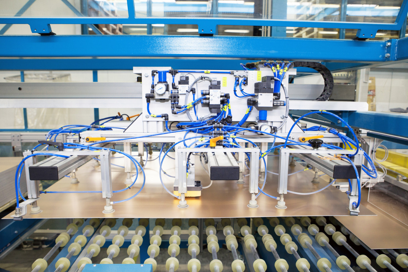 Fig. 4: Fully automatic dividing line for base materialInELIC,the plated-through inner layer is exposed to the most temperature cycles, while the following prepreg layers are exposed to less and less towards the outside. The effect of this temperature load can be seen in measurement series T288: the more often a base material is exposed to high temperatures, the shorter the time to delamination.
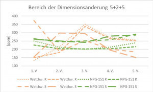
Anyone who manufactures multilayers knows that dimensional changes occur particularly during the pressing process - the higher the resin content and the thinner the glass fabric, the more pronounced the changes. The correlation between resin content and z-axis expansion is also well known. All of these factors, which are challenging in terms of process technology, come together to a great extent in smartphone PCBs and to a lesser extent in complex PCBs for other applications.
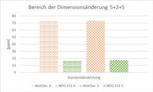
This was the aim of the product development of NPG-151. The rheology of the resin system in combination with Nan Ya glass fabrics leads to reproducible and therefore more controllable dimensional changes in the production of selectively pressed multilayers.
The ideal state, in which stacked microvias lie vertically on top of each other, is achieved when the entire conductor pattern expands or shrinks at right angles, equally in all axes. The NPG-151 comes very close to this in a comparative study with a competitor product in a real 5+2+5 smartphone circuit board (see Fig. 3).
Despite the high number of layers, the ELIC PCBs are very thin and the components to be assembled are sometimes extremely small. The PCBs must have a high degree of rigidity for positioning during assembly and in the reflow processes. In the peak range of a typical reflow process at 250 °C, for example, the stiffness of NPG-151 is almost 60 % higher than that of NPG-150N.
The product life cycles of base materials were discussed at the beginning; these cycles naturally also exist for the end products, which can be relatively short for smartphones but very long for industrial or automotive applications.
If only one or very few base materials are qualified for a product, the product life cycle of the base material and applications must correspond. Technolam is focused on the needs of European PCB manufacturers and their products. When compiling the current and future base material portfolio, the focus is on a wide range of applications and their long-term availability.
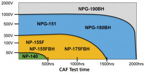 Diagram 3: Recommended base material classes for different CAF test conditionsNPG-151was tested positively in the CAF test of a European automotive OEM at 500 V and 1000 V for 5600 h in each case. This is accompanied by a commitment to support the product life cycle. With the growing realization that the highest CAF resistance on the part of the base material is achieved with halogen-free resin systems, further applications in the context of e-mobility will follow. NPG denotes halogen-free in the Nan Ya nomenclature, and Diagram 3 shows Nan Ya's material recommendation for different application or test conditions.
NPG-151 was UL-listed in 2013, and after ten years on the market, it is fair to say that it is a long-runner. Initially for smartphones, it has also been increasingly used for automotive applications in the high-voltage sector since 2018.
At the end of 2021, the production volume of NPG-150N and NPG-151 was at parity. Since then, the share has increasingly shifted in favor of NPG-151. This is a clear sign that new developments are starting with NPG-151 and, to stay with the product life cycle, NPG-150N applications are in the degeneration phase.
This shift naturally has an impact on production planning. Even as the world's second largest base material manufacturer, Nan Ya cannot maintain unlimited production capacities. In order to manufacture economically, NPG-150N will only be produced on a few lines in the first stage and in campaigns in a second stage. Nan Ya and Technolam both aim to see customer projects through to completion. Even if there is no hard production stop for NPG-150N, new projects should always be started with NPG-151. The demands on printed circuit boards manufactured in Europe will grow, even if the possibility of pressing seven times with NPG-151 is more of a safety reserve than a technical necessity for projects planned now. But from a long-term perspective, it is definitely the right choice to opt for a base material that will be a long runner for some time to come due to its technical properties.
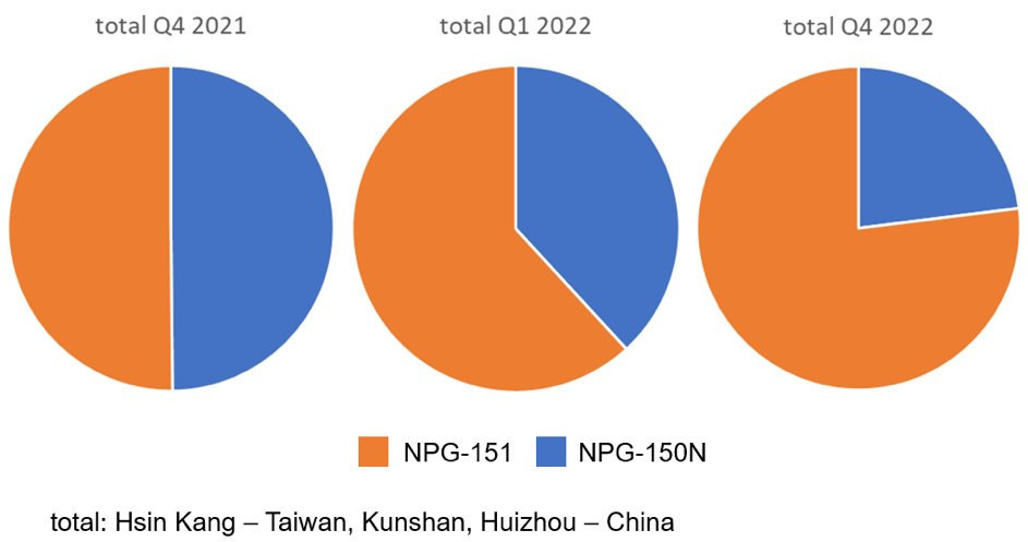 Diagram 4: Development of the production share of old and new generation halogen-free base material


