
Metallic materials offer a good compromise between hardness and ductility: before they break, they first deform. This in turn poses certain challenges for the coating.
Every component has to transmit some kind of force, even if it is only its own weight.

This requires a certain strength, which is the product of the specific strength (hardness, elasticity E or tensile strength σ or Rm) and the respective cross-section.
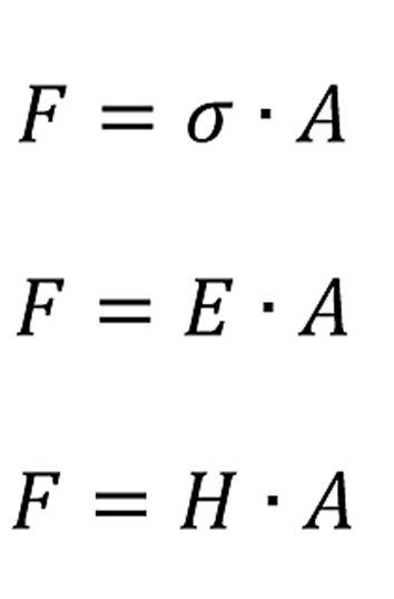
Lightweight construction now means realizing the same function with less material mass. To achieve this, the cross-sections of the component must be reduced. For the same force, the following applies
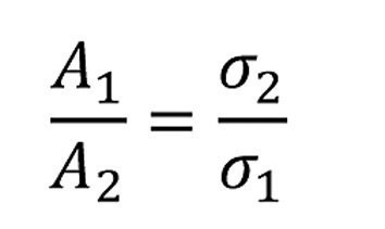
If the cross-section is reduced by the factor C, i.e.A1 = C -A2, the strength must increase by the same factor, i.e. σ2 = C - σ1
The advantage of metallic materials is that each metal offers a certain compromise between strength and ductility. In contrast to brittle materials, which break immediately when overloaded, a metal component initially deforms plastically. This generally increases its strength and makes it last longer. This gives it time to prevent damage.
For lightweight construction, the materials must therefore be made stronger and less ductile. What mechanisms are available to metallurgy for this?
Plastic deformation means that the workpiece deforms without the bonds as a whole breaking (fracture). During deformation, only individual bonds are allowed to break and others to close in order to maintain the strength of the body. How can this work?
The smoother the surfaces are, the easier it is for them to slide against each other. In a crystal, the sliding surfaces are the surfaces with the densest sphere packing because they are the "smoothest". If the stresses resulting from the calculation of this displacement are compared with experimental results (in Tab. 1 "Displacements"), it can be seen that they differ by around three orders of magnitude (Tab. 1) [1].
| Material | Sliding plane τ | Displacement τ |
σb |
| GPa | MPa | MPa | |
| α-Fe |
2,6 |
27,5 |
150 |
|
Ni |
2,6 |
3,2 |
121 |
|
Cu |
1,4 |
0,49 |
51 |
|
A1 |
0,9 |
0.78 |
30 |
There must therefore be a mechanism that acts at lower forces. Let us take the example of moving a carpet on a flat surface. If you want to move it as a whole, you need a large force. However, if you move it over a wave (fold), a much smaller force is sufficient (Fig. 1).
") Fig. 1: Moving a carpet over a fold (without moving the sliding surface as a whole)
Fig. 1: Moving a carpet over a fold (without moving the sliding surface as a whole)
In metal, this corresponds to the movement of a dislocation.
This means that considerably less energy is required to move it than to move the entire sliding plane (about three orders of magnitude). The main method of increasing strength is to block the movement of dislocations.
The conclusion from Table 1 is that initially only the dislocations move. If they are all blocked, a sliding plane can shift at a correspondingly high stress. Incidentally, these can be seen particularly clearly when bending; steps are created between the sliding planes on the outer bend.
When the step dislocations move (Fig. 2), only one row of bindings ever has to fold over. As a result, the force required is relatively low.
![Abb. 2: Stufenversetzung [2]](/images/stories/thumbnails/gt-2020-11-0095.jpg "Abb. 2: Stufenversetzung [2]") Fig. 2: Step dislocation [2]
Fig. 2: Step dislocation [2]
Figure 2 shows the stress fields of a stepped dislocation. Compressive stress prevails in the area of the additional half plane and tensile stress in the area below.
If the stress fields collide with others during the movement of a dislocation, they block each other. The deformation can no longer progress in this way. Hardness and strength have increased accordingly.
The strength of a metallic material is a function of
- the bonding conditions in its crystal lattice and
- the mobility of the disorder, in particular the step dislocations.
What possibilities does metallurgy have to increase strength?
The increase in the strength of the metal is accompanied by an increase in the disordering compared to the ideal crystal. Types of defects in the crystal are summarized in Table 2:
The defects lead to pre-stressing of the bonds in the crystal by compression (compressive stress) or strain (tensile stress).
Figures 3 to 6 show the point defects with their stress fields.
 Fig. 3: Defect with tensile stress area
 mit Druckspannungsbereich") Fig. 4: Intercalated crystal (interstitial atom) with compressive stress range
Fig. 4: Intercalated crystal (interstitial atom) with compressive stress range
 Fig. 5: Substitution by a smaller atom with tensile stress range
 Fig. 6: Substitution by a larger impurity atom with compressive stress range
A defect in the lattice can also occur in a super-pure single crystal. It is a stacking fault without the involvement of impurity atoms.
Only small atoms that harden or are used for hardening can intercalate: Hydrogen, carbon, nitrogen.
If a smaller atom sits on a lattice site, tensile stresses arise as in the case of the defect, only of a smaller size.
With a larger atom on a regular lattice site, compressive stresses arise which are generally lower than when an intermediate lattice site is occupied.
In any case, the bond lengths between the atoms deviate from the normal value; they are compressed or stretched. This means that they contain more energy than the undisturbed environment.
This means for the anodic process (corrosion, etching treatment):
Initially, the metal dissolution rate increases with the energy introduced E = k - K1

or electrochemically
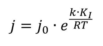
This means that the pickling/etching process is faster with greater deformation. The more highly deformed areas of the workpiece are preferentially attacked. On the other hand, this also means that hydrogen embrittlement and the tendency to blistering are somewhat higher in these harder areas. Here is a practical example. Punched perforated sheets were galvanized. Blisters formed above the holes. The material was more deformed at these points. During galvanic treatment, especially during pre-treatment, but also during galvanizing, the hydrogen remained in these areas (small horizontal surface) for a little longer and was able to penetrate to a greater extent. The pre-exposure to hydrogen from the metallurgy was practically the same at all points. However, it was so high that the small additional load at these points caused bubbles to form.
What methods are available to metallurgy to realize lightweight construction?
The methods for increasing strength are almost all based on hindering the mobility of the dislocations. Strength-increasing measures are
- Cold forming: this increases the dislocation density and thus the internal energy of the crystal lattice. This must be applied during forming in addition to the displacement energy of a step dislocation (Peierl stress =~ 5-104 Pa).
The electrochemical effect is that the "solution pressure" is increased. The potential becomes more negative. - Solid solution solidification: By incorporating a foreign atom into the lattice (doping; alloying), the original lattice is strained and thus its internal energy is increased. A distinction must be made between substitutional solid solution (regular lattice site) and interstitial solid solution (interstitial lattice site) with regard to the position of the impurity atom. The impurity atoms tend to accumulate as "clouds" around the dislocations. In this way, they additionally hinder their movement. Electrochemically, the effect is such that a mixed potential is formed for this area according to the concentrations of the alloy components and their normal potentials, which deviates from the neighboring area with a lower concentration of impurity atoms. Whether it is more positive or more negative than that of the base material depends on the potential of the alloying element [5].
- Fine grain strengthening: When the microstructure grains are refined, the proportion of large angle grain boundaries per unit volume increases. The grain boundaries naturally act as a brake on the movement of the dislocations.
Electrochemically, the effect is such that the corrosion resistance is improved, although the impurities accumulate at the grain boundaries. The general effect in electroplating can be seen from the fact that the same corrosion test times are achieved today with significantly thinner layers than 70 years ago. However, the boundary areas are also narrower (greater homogeneity of the distribution of impurities) and the path for intercrystalline corrosion is therefore longer. - Precipitation hardening; the solubility of secondary phases in the alloy changes depending on the temperature of the material. It decreases with falling temperature and these precipitate during cooling. Precipitates can vary greatly in terms of their distribution, size and shape. If the proportion of the secondary phase is sufficient and it is distributed accordingly, it not only disrupts the movement of the dislocations, but also generates new dislocations (Frank-Read mechanism).
Electrochemically, the effect is such that the precipitated areas have a significantly different potential than the secondary areas. This leads to the formation of localized elements. The workpiece surface becomes differently opaque. In the case of anodic oxidation, these precipitates, when they reach the size of the oxide layer (4-5 nm), lead to a short circuit in the oxide layer. As a result, the oxidation is concentrated in points. - Transformation hardening: This is only significant for the formation of martensite in steel.
Inhomogeneities occur at roughnesses, inclusions and roll-ins. However, they can also occur when individual atoms are detached from the structure. Grain boundaries are particularly inhomogeneous.
Metallurgy attempts to compensate for inhomogeneities through thermal post-treatment. Various processes are available for this purpose.
Diffusion annealing
Diffusion only ever takes place in one direction: from the higher to the lower concentration. The equalization of concentration during diffusion annealing leads to hardening, strengthening and higher corrosion resistance (due to lower potential differences in the surface).
Recrystallization annealing
Reduction of dislocations and the associated internal stresses due to crystal recovery at T > 0.4TSchm. No new microstructure formation.
Work hardening
Deformation at T < 0.4TSchm. Atoms slide out of the lattice plane. The microstructure is destroyed more with increasing deformation. Deformation on the surface leads to a Beilby layer.
Heat treatment, general
Objective: To change material properties by reducing microstructural defects after cold forming, or to avoid fractures between two cold forming operations, or after cooling defects.
Hardening
Or more precisely precipitation hardening, by precipitation of components from the solid solution during cooling. This is caused by the lower solubility in the cold. The faster the cooling, the lower the precipitation and the higher the stress in the lattice.
Non-destructive optical inspection methods are used to evaluate the color, gloss, degree of roughness and the presence of various defects (flakes, splinters, bubbles, cracks) (normal vision or appropriately corrected eye, certain magnifications (6x, 10x, ... up to several 10,000x in the electron microscope).
The physical basis of the optical control methods is the interaction of the visible spectrum (radiation with wavelengths from 0.1 to 1000 µm) with the object being examined. The main range for the examination light is 0.4-0.78 µm.
The change in spectral or integral photometric data caused by the change in physical surface properties leads to corresponding changes in the amplitude, frequency, phase, polarization and degree of coherence of the light. The basic physical effects caused by the modulation of the parameters of the test specimens, which can be observed with optical methods from the normal or appropriately corrected eye to the electron microscope, include effects of the galvanic layer, such as density (cracks, scratches, porosity, delamination (bubbles, flaking), spotting, burns on corners and edges, defects, pitting), changes in coloration and gloss as well as microgeometry (roughness), but also the defect distribution. This means that a number of effects of the hardening of the base material (see Table 2) can also be detected in this way. The optical inspection methods can also be easily automated today.
|
Point defects |
zero-dimensional lattice defects |
|
|
foreign atoms |
in homogeneous solution |
Substitution atoms, max. size difference: 14 %, same lattice type, too high content leads to cluster formation, precipitation hardening. Content leads to cluster formation, precipitation hardening |
|
Vacancies |
Defect frequency increases exponentially with temperature and degree of deformation, at RT 108 /cm3 |
|
|
Interstitial atoms |
Interstitial atom, the lattice is expanded around the additional atom (compressive stress region), common type of atom: hydrogen C and N for hardening |
|
|
Line defects |
one-dimensional lattice defects |
|
|
step dislocation
|
A lattice line ends irregularly, resulting in compressive stresses (around the irregular plane) and tensile stresses (in the area where the irregular plane is missing), dislocation line and Burgers vector are perpendicular to each other |
|
|
Screw dislocation |
Displacement of two half planes against each other. |
|
|
Surface defects |
Two-dimensional grid defects |
|
|
grain boundaries |
Large angle grain boundaries |
>10°, larger distances between the grains (several atomic distances) |
|
Phase boundaries |
||
|
Small angle boundaries |
Cause of the subgrains |
|
|
Twin boundaries |
Special form of the grain boundary |
The two crystal halves share an atomic row as a boundary |
|
Stacking fault |
Interruption of the regular arrangement of the lattice planes |
lead to grain boundaries and thus to polycrystals (prevent the formation of single crystals) |
|
Ferromagnetic domains |
||
|
ferroelectric domains |
||
|
volume defects |
three-dimensional lattice defects |
complete impurity phase in the crystal |
|
precipitates |
impurity phase formed from the crystal itself |
|
|
screw dislocations |
Burgers vector and dislocation line are parallel to each other |
|
|
pores |
Open or closed cavities |
filled with gas or liquid |
|
inclusions |
solid foreign phase in the crystal |
The defect size is particularly problematic. When inspected with the naked eye, there is still a certain degree of conformity with the metallurgy. On delivery to the customer, inspection is often carried out using a magnifying glass or microscope. This inevitably reveals defects that are not defects in metallurgy. However, as the electroplater is not actually responsible for them, the question arises as to who bears the costs.
Effects that are particularly difficult to predict arise with the formation of intermetallic compounds in high-strength alloys.
Precipitation via Guinier-Preston zones begins even before the formation of intermetallic compounds. These are areas created by segregation processes in which the atoms of a supersaturated alloy element form rod-shaped or platelet-shaped clusters in the range of a few nanometers. Such processes are not only the cause of an increase in the hardness and brittleness of some alloys during temperature treatment or ageing, but also of areas with different potentials and therefore prerequisites for corrosion.
Intermetallic compounds are homogeneous chemical compounds of two or more metals. In their lattice, which differs from that of the parent metals, there is a mixed bond consisting of a proportion of metallic bonding and lower proportions of atomic bonding or ionic bonding. The metals are bound more tightly than with a pure metal bond. They are very hard compared to the metals they form and the specific resistances are higher. The electroplater may also encounter "exotic" elements. Intermetallic compounds, e.g. with silicon, can lead to negative effects during anodizing. This is the case when segregations occur (segregate, clean). Segregations are segregations of a melt that lead to a local increase in the concentration of individual elements. They occur when the solubility in the solid state is lower than in the melt. They are intentional for precipitation hardening.
Every obstacle increases Rp, the yield point. Every measure that changes the yield point also changes all other mechanical parameters and not just these. Structural defects occur during casting and cooling and are multiplied during forming.
To the extent that the movement of the dislocations is impeded, the limit of elastic load-bearing capacity increases. Ultimately, the technically desired strength of the material is shifted upwards. In most cases, however, this is at the expense of plastic deformability. The strength increases in proportion to the square root of the dislocation density:
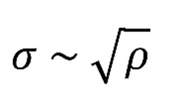
ρ - dislocation density
The dislocation density is defined as the total length of the dislocations in a volume (m/m3, abbreviated m-2). A value of 108 m/m3 was achieved with specially grown single crystals. However, even with undeformed samples, values in the order of 1012 m/m3 are generally found, with strongly deformed samples values of up to 1015 m/m3. Or to put it more clearly: 1000 to 1 million km/cm3 [4]. - to be continued -
Literature
[1] Gottstein, G.: Physikalische Grundlagen der Materialkunde, Springer-Verlag, Berlin Heidelberg New York, 2001
[2] https://www.ahoefler.de/images/maschinenbau/werkstoffkunde/verformbarkeit-der-metalle/verformung-realkristall/versetzung.png
[3] Unruh, J.N.M.: Galvanotechnik table book, from edition 7, Eugen G. Leuze Verl., Bad Saulgau
[4] https://de.wikibooks.org/wiki/Werkstoffkunde_Metall/_Innerer_Aufbau/_Gitterfehler
[5] Unruh, J.N.M.: The automotive alloy ZnNi14 and its potential ratios, Galvanotechnik, 111(9), 2020, 1341
