
In electroplating and electrometallurgy, compact, even metal deposits are generally desired. Today, on the basis of theoretical knowledge and empirical findings, it is possible to achieve the desired uniform metal deposits by using suitable organic additives. They are divided into inhibitors and catalysts. The former were recognized as levellers in the 1960s and 70s, the levelling effect of catalysts only in the 80s.
Leveling theories such as the "diffusion-controlled" [1] or the "surface-controlled" [2] leveling mechanism can describe the leveling of microprofiles by organic additives with sufficient precision and make predictions about the suitability of organic additives for the electrochemical deposition of a wide variety of metals on the basis of simple experiments. With organic additives, not only the leveling, but also the roughening of microprofiles by organic additives can be understood and, if necessary, roughness can be specifically adjusted [4, 5].
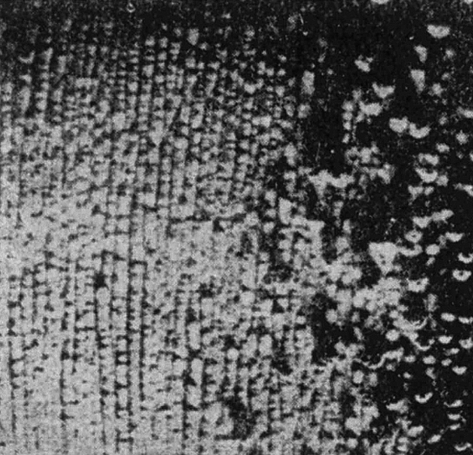
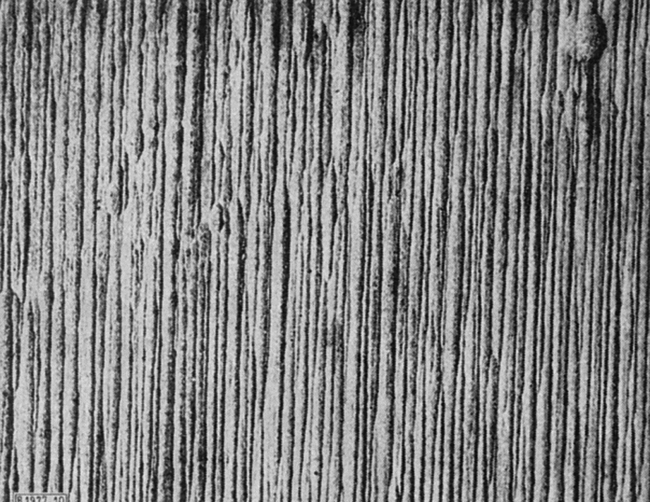
Fig. 1: a) Left: Grooved copper deposition on cylindrical cathodes at high rotational speed [9]; b) right: Grooved cathode structure during copper refining electrolysis [10]
In terms of their electrochemical effectiveness, organic additives are divided into inhibitors and catalysts/accelerators, depending on whether they inhibit or facilitate metal deposition. Historically, inhibitors were first recognized as levellers of microroughness in the 1960s and 1970s and their levelling effect was explained by the diffusion of inhibiting organic molecules through the Nernst diffusion layer to the microrough cathode surface [1]. The levelling effect of catalysts/accelerators, on the other hand, was only recognized in the 1980s [2].
Due to the shorter diffusion paths of the inhibitors through the Nernst diffusion layer to the peaks of the micro-roughnesses compared to the longer paths to their valleys, the diffusion-controlled mechanism results in the increased inhibitor occupancy of the peaks necessary for leveling and the lower inhibitor concentration in the roughness valleys. The diffusion-controlled leveling theory also requires that the inhibitor is either incorporated into the precipitate and/or converted at the cathode surface, so that a concentration gradient of the organic additives can occur in the diffusion layer. In fact, corresponding degradation products of the inhibitors have been detected in the leveled precipitates of various metals [6].
In the surface-controlled mechanism, catalytically/acceleratorically active organic additives are a prerequisite for leveling, whereby their uneven distribution on the microrough cathode surface required for leveling is not dependent on the mass transport conditions, but is controlled by the growth of the microrough surface itself. All that is required of the catalysts/accelerators is that they "sit" in their place on the microrough surface for a sufficiently long time during surface growth. The theory shows that the different geometric changes at the peaks and valleys of the initially uniformly growing microrough surface lead to a change in the catalyst/accelerator concentration in the valleys and peaks of the microrough surface. The initial uniform catalyst/accelerator occupancy of the microrough surface increases during uniform growth in the valleys of the microroughs and decreases over the peaks, since during uniform growth the surface area decreases in the valleys and increases on the peaks for geometric reasons alone. Since the organic molecules remain firmly adsorbed at their surface location during layer growth, the catalyst/accelerator concentration distribution required for leveling is created in this way on the microrough surface.
The surface-controlled leveling mechanism provided the theoretical basis [4] for the copper technology empirically developed by IBM at the end of the 1990s and the so-called Damascene process for chip production as well as for through-hole plating in printed circuit boards.
The inhibiting effect of diffusion-controlled organic additives, like the diffusion of metal ions to the cathode, depends directly on the flow conditions in front of the cathode. Stronger currents in front of the cathode lead to a lower diffusion layer thickness, which not only leads to increased metal ion transport to the cathode, but also makes the concentration gradient for the inhibitors steeper and thus increases the inhibitor concentration and the inhibiting effect at points on the surface where the flow has led to a local reduction in the diffusion layer thickness. As already mentioned, the prerequisite for this is that inhibitor conversion takes place at the cathode. In this way, inhibitors can also influence the deposition structures on a macrometer scale. For example, flow plastics can be formed by different flow conditions on the cathode surface, the characteristics of which are significantly influenced by the addition of inhibitors. Flow plastics were first investigated by Matschke [7] and made known by Fischer [8]. Since the observed patterns of metal deposition were particularly pronounced when inhibiting additives were used in the electrolyte, it was reasonable to assume that the precipitation patterns were determined by the interaction of the hydrodynamic situation in front of the cathode and the inhibiting organic additives.
Billiter [9], for example, reported on the formation of flow plastics during the electroforming of copper tubes. Interestingly, Billiter showed that a periodic groove pattern formed when the tubes rotated around the longitudinal axis during electroforming copper deposition (Fig. 1a) [9].
Grooved copper precipitates were also observed during copper refining electrolysis from electrolytes with organic inhibitors used to prevent budding (Fig. 1b) [10]. Such a grooved structure is undesirable as the copper cathode quality can deteriorate if the grooves are so deep that electrolyte inclusions become possible.
Grooved structures have also been observed during copper deposition on a current-carrying cathode [11].
The cause of the groove-shaped copper deposition during copper refining electrolysis was unclear for a long time. The vertical orientation of the groove structure in the direction of the natural convection flow in front of the cathode plates and the striking uniformity of the number of grooves per unit length led to the assumption that there must have been a comparable periodic flow pattern in the convection flow, which became visible as a macromorphological "fingerprint" in the copper coating [12, 13].
![Abb. 2: Taylor-Görtler Wirbel an konkav gekrümmter und geneigter Oberfläche [16]](/images/stories/Abo-2023-05/gt-2023-05-055.jpg "Abb. 2: Taylor-Görtler Wirbel an konkav gekrümmter und geneigter Oberfläche [16]") Fig. 2: Taylor-Görtler vortex on a concavely curved and inclined surface [16]
Fig. 2: Taylor-Görtler vortex on a concavely curved and inclined surface [16]
In fact, periodic flow structures are observed in hydrodynamics, both in forced and natural convection, when a laminar flow boundary layer becomes unstable due to disturbances and a sometimes extremely stable transitional structure in the form of a vortex tube system of counter-rotating vortex tubes is formed in the transition region from laminar to turbulent flow (cover picture and Fig. 2) [15, 16]. Such vortex tube systems are known as Taylor-Görtler vortices and are formed, for example, between rotating cylinders, on a rotating disk or with a positively inclined or concavely curved surface when a characteristic Reynolds number is exceeded in the case of forced convection or a critical Rayleigh number in the case of natural convection.
If such a flow structure is present in the flow boundary layer, it is imprinted on the Nernst diffusion layer during electrodeposition, which results in a correspondingly periodically varying thickness of the Nernst diffusion layer for the metal ions and the inhibitor transfer to the cathode surface (Fig. 3).
![Abb. 3: Aufprägung gegenläufig rotierender Taylor-Görtler- Wirbel vor positiv geneigter Oberfläche auf die Nernstsche Diffusionsschicht [12, 13]](/images/stories/Abo-2023-05/gt-2023-05-056.jpg "Abb. 3: Aufprägung gegenläufig rotierender Taylor-Görtler- Wirbel vor positiv geneigter Oberfläche auf die Nernstsche Diffusionsschicht [12, 13]") Fig. 3: Imprinting of counter-rotating Taylor-Görtler vortices in front of a positively inclined surface on the Nernst diffusion layer [12, 13]
Fig. 3: Imprinting of counter-rotating Taylor-Görtler vortices in front of a positively inclined surface on the Nernst diffusion layer [12, 13]
In contrast to the leveling of micro-roughness, in this case the different diffusion paths for metal ions and inhibitors are generated on the Nernst diffusion layer side facing the hydrodynamic boundary layer and not by the micro-roughness on the cathode surface. The vortex tube patterns in the hydrodynamic boundary layer are much larger compared to the micro-roughnesses and are in the upper micrometer to millimeter range.
This results in a corresponding macroscopic pattern of different inhibitor concentrations on the cathode surface, which has a corresponding effect on the metal deposition. In the case of the vortex tube formation, its periodic hydrodynamic pattern is imprinted on the Nernst diffusion layer in such a way that, alternating periodically, more metal ions, but also more inhibitors, are deposited on the surface at locations with a lower diffusion layer thickness than at locations with a greater diffusion layer thickness (Fig. 4).
![Abb. 4: Ungleichförmige Inhibitor-Verteilung durch Taylor-Görtler-Wirbel [14]](/images/stories/Abo-2023-05/gt-2023-05-057.jpg "Abb. 4: Ungleichförmige Inhibitor-Verteilung durch Taylor-Görtler-Wirbel [14]") Fig. 4: Non-uniform inhibitor distribution due to Taylor-Görtler vortices [14]
Fig. 4: Non-uniform inhibitor distribution due to Taylor-Görtler vortices [14]
Landau and Osterwald [12, 13] used various visualization methods to detect and visualize the vortex tube patterns in front of the cathodes during electrolytic copper deposition. With the help of anodically formed, very fine copper powder, which was carried along by the natural convection flow in front of a slightly positively inclined cathode, it was possible, for example, to visualize the three-dimensional structure of the Taylor-Görtler vortex tube pairs by means of a horizontal light section through the vortex tubes (Fig. 5).
![Abb. 5: Horizontaler Lichtschnitt durch die mit Hilfe von feinstem, anodisch gebildeten, Kupfer- pulver vor der Kathode sichtbar gemachten Taylor-Görtler- Wirbelpaare [12]](/images/stories/Abo-2023-05/gt-2023-05-058.jpg "Abb. 5: Horizontaler Lichtschnitt durch die mit Hilfe von feinstem, anodisch gebildeten, Kupfer- pulver vor der Kathode sichtbar gemachten Taylor-Görtler- Wirbelpaare [12]") Fig. 5: Horizontal light section through the Taylor-Görtler vortex pairs made visible in front of the cathode with the aid of the finest, anodically formed copper powder [12]
Fig. 5: Horizontal light section through the Taylor-Görtler vortex pairs made visible in front of the cathode with the aid of the finest, anodically formed copper powder [12]
Landau and Osterwald [12, 13] were able to show in their studies on electroplated copper deposition using inhibitors that vortex tubes in the natural convection flow at cathodes are triggered by an artificially applied, non-conductive obstacle even with a slight positive inclination (Fig. 6a) and even with a vertical cathode position (Fig. 6b), thus creating the characteristic groove structure in the area above the disturbance in the copper deposit. In the areas outside the disturbed area, the laminar flow continued to dominate and led to a leveled, uniform copper deposit.
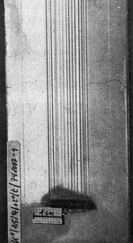
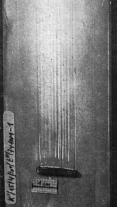
Fig. 6: Left: a) α = + 2°; right b) α = 0° ;groove structure above the roughness element after 3 h of electrolysis at 250 A/m2 [11]
![Abb. 7: Riefenstruktur bei der Vernicklung mit stark einebnendem kommerziellen Additiv [12]](/images/stories/Abo-2023-05/gt-2023-05-061.jpg "Abb. 7: Riefenstruktur bei der Vernicklung mit stark einebnendem kommerziellen Additiv [12]") Fig. 7: Scoring structure during nickel plating with a strongly levelingcommercial additive [12] In nickel deposition, the vortex tube system formed on a concavely curved cathode surface also led to a pronounced periodic nickel scoring structure when a commercial inhibitor system with a high leveling strength was used (Fig. 7) [12].
Fig. 7: Scoring structure during nickel plating with a strongly levelingcommercial additive [12] In nickel deposition, the vortex tube system formed on a concavely curved cathode surface also led to a pronounced periodic nickel scoring structure when a commercial inhibitor system with a high leveling strength was used (Fig. 7) [12].
The fact that the strength of the scoring depends on the type and concentration of the organic inhibitors used as well as the current density was to be expected based on the knowledge of the diffusion-controlled leveling theory. Since copper deposition in electroplating and electrometallurgical practice, as well as in the laboratory tests, took place in a current density range in which the deposition kinetics are still determined by a penetration inhibition and less by transport inhibition, it is not surprising that the development of the groove structure in the additive-free electrolyte was comparatively low (Fig. 8, dashed line). In the area of medium inhibitor concentration, a surprisingly strong maximum of the groove depth occurred in the copper groove structure, the maximum value of which was increased by a factor of about 13 compared to the additive-free copper electrolyte (dashed line) (Fig. 8).
On the basis of these results, there was every indication that the problem of the undesirable groove structure on the copper cathodes in copper refining electrolysis was primarily due to the inhibitors used and/or their unfavorable inhibitor concentration and only indirectly to the Taylor-Görtler vortex tubes, which can probably hardly be avoided in practice.
According to the curve shown above (Fig. 8), an inhibitor concentration at one of the two minima was suggested for the prevention of scoring. In practice, preference was given to the minimum at lower concentrations, as with the other minimum at a high inhibitor concentration there was a risk of slipping into the area of greatly increased scoring due to consumption of the additive.
The fact that the surface-controlled levellers, which act independently of the transport conditions, can solve the scoring problem even more easily with sufficient levelling force can be seen in Figure 8 for the entire catalyst/accelerator concentration range (black measuring points) - including the catalyst/accelerator concentration range with the highest levelling capacity. Over the entire concentration range, the groove depth measured in laboratory tests is not greater than in the additive-free copper electrolyte.
Using the surface-controlled levellers, hydrodynamic structures such as the Taylor-Görtler vortex tubes in front of the cathodes can lead to no pronounced macroscopic flow patterns on the cathode surfaces at current densities normally used in electroplating and refining electrolysis - i.e. far from the limiting current density - and still achieve smooth, microscopically leveled surfaces. The same also applies to any form of flow plasticity, which can be largely avoided with the right choice of leveler, without having to do without a leveled galvanic deposit. Thanks to the knowledge of how organic additives work during electrochemical leveling and the causes of scoring, scoring is no longer a real problem on copper cathodes in copper refining electrolysis.
![Abb. 8: Abhängigkeit der mittleren Riefentiefe von der Zusatzkonzentration bei 25 °C, 250 A/m2 und 1 h Elektrolyse; Elektrolyt: 54 g/l Cu, 60 g/l H2SO4, 80 mg/l NaCl (ohne Additive/mit Inhibitor/mit Katalysator [12, 13]](/images/stories/Abo-2023-05/gt-2023-05-062.jpg "Abb. 8: Abhängigkeit der mittleren Riefentiefe von der Zusatzkonzentration bei 25 °C, 250 A/m2 und 1 h Elektrolyse; Elektrolyt: 54 g/l Cu, 60 g/l H2SO4, 80 mg/l NaCl (ohne Additive/mit Inhibitor/mit Katalysator [12, 13]") Fig. 8: Dependence of the average scoring depth on the additive concentration at 25 °C, 250 A/m2 and 1 h electrolysis; electrolyte: 54 g/L Cu, 60 g/L H2SO4, 80 mg/L NaCl (without additives/with inhibitor/with catalyst [12, 13]
Fig. 8: Dependence of the average scoring depth on the additive concentration at 25 °C, 250 A/m2 and 1 h electrolysis; electrolyte: 54 g/L Cu, 60 g/L H2SO4, 80 mg/L NaCl (without additives/with inhibitor/with catalyst [12, 13]
If flow plastics are used to characterize the hydrodynamic conditions during electrolytic metal deposition [11], it makes sense to use correspondingly strong levelling, transport-controlled inhibitors.
Current knowledge of the interaction of hydrodynamics and organic additives in electrochemical metal deposition allows the conclusion to be drawn that the scoring pattern on the rotating copper tubes described by Billiter was certainly caused by the Taylor-Görtler vortex tubes created by the rotation and the organic additives used.
Literature
[1] Kardos, O.: Plating 61, 1974, 129, 229, 316
[2] Osterwald, J.; Schulz-Harder, J.: Galvanotechnik 66, 1975, 360
[3] Landau, U.: Electroplating technology 113, 2015, 1176
[4] Osterwald, J.: Surface Surface, 17, 1976, 89
[5] Osterwald, J., Schulte, H.: Galvanotechnik 67, 1976, 440
[6] Edwards, J.: Aspects of Addition Agent Behavior, Proc. 6th Int. Conf. of Met. Fin. 1964, 22-34
[7] Matschke, H.: Dipl. Arbeit, Techn. Univ. Berlin, 1949
[8] Fischer, H.: Electrolytic Deposition and Electrocrystallization of Metals, Springer-Verlag, Berlin/Göttingen/Heidelberg, 1954, 105 f
[9] Billiter, J.: Technische Elektrochemie, Bd. I, Knapp/Halle (Saale) publishing house, 1952, 115
[10] Süssmuth, E.: Chemie-Ingenieur-Technik, 37, 1965, 590
[11] Kutzschbach, P.: Galvanotechnik 96, 2005, 560
[12] Landau, U.: Diss. TU Berlin, 1976
[13] Landau, U., Osterwald, J.: Erzmetall, 29, 1976, 103
[14] Kammel, R., Landau, U., Meyer, M.: Erzmetall 36, 1983, 465
[15] Schlichting, H.: Boundary-Layer Theory, McGraw-Hill Book Company, 1968, 501
[16] Schlichting, H.: Boundary-Layer Theory, Braunsche Hofdruckerei und Verlag GmbH, Karlsruhe, 1951, 326
