Aging phenomena are well known in the electronics industry: Both components and component housings are affected. Such signs of ageing also have an influence on the dielectric properties of the materials used in HF applications - with consequences including functional failure. To prevent this, the materials used in the HF environment - as well as mechanical and electrical contacts - must be verified for the operating conditions in order to clarify the influence of ageing on the function-determining parameters. To date, however, this important issue has only been given insufficient consideration, although findings in this regard should already be incorporated into the initial design concepts.
Aging phenomena are well known in the electronics industry: Both components and packagings are affected. Such aging phenomena also have an influence on the dielectric properties of the materials used in RF applications - with consequences that can extend to functional failure. To prevent this, the materials used in the RF environment - as well as mechanical and electrical contacts - must be verified for the operating conditions in order to clarify the influence of aging on the function-determining parameters. To date, however, this important issue has been insufficiently considered, although findings in this regard should already be incorporated in the initial design concepts.
 Fig. 1: Geometry of an open resonator: configurationWiththe growing interest in autonomous vehicles, the need for integration technologies for the necessary radar systems has also increased. In particular, questions of mm-wave packaging in the 77GHz and 79GHz frequency bands for short-, medium- and long-range radars are in demand [1, 2]. In order to guarantee safe operation, especially for critical passenger safety applications, even over years of use in demanding operating environments, the materials and components used are put through their paces with reliability tests. The overarching criterion here is the probability that such a system will fulfill its function without failure over a specified period of time under the specified conditions [3]. Since such tests obviously cannot be carried out sensibly and within an acceptable time frame under real field conditions, tests in a laboratory environment under suitable acceleration conditions are a common approach. Failure criteria adapted to the test conditions may also need to be defined. In the field of electronics reliability, the electrical contact is often this target value, which is also used in corresponding design specifications (Design for Reliability) [4]. In addition, the protective properties of the housing and thermal load management are also used as criteria [5].
In contrast to these issues, a central question in mmWave integration is how the high-frequency signals are routed and distributed without loss or interference (signal integrity - SI). If antenna structures are also installed in the RF setup, the desired radiation parameters and electromagnetic integrity (EMI) must also be considered.
Essential for these parameters are the dielectric properties of the materials used, e.g. the relative dielectric constant (er) and the loss angle (loss tangent d), which are decisive for the desired function - and are already taken into account in the design.
If these material data are not correct, this leads to mismatching, signal delay interference, attenuation and distorted radiation characteristics - in other words, a system malfunction.
Components and component housings affected
Ageing phenomena are well known in the electronics industry, affecting both components and component housings. Such signs of ageing also affect the dielectric properties of the materials in HF applications - with the aforementioned consequences, including functional failure.
In order to prevent such scenarios, the materials used in the HF environment - as well as mechanical and electrical contacts - must be verified for the operating conditions in order to clarify the influence of ageing on the function-determining parameters. To date, however, this important issue has only been insufficiently considered, although findings in this regard should already be integrated into the initial design concepts.
This paper presents a comprehensive study on the influence of ageing processes on integrated RF packages in the 77 and 79 GHz radar frequencies, which are of interest in the automotive environment. This methodology is exemplified using a material widely used in RF applications, Panasonic Megtron 6. Three test structures (microstrip line, grounded coplanar line and a patch antenna) are used as application examples for the 79GHz band.
Sample preparation and accelerated ageing tests
The Panasonic Megtron 6, R-5775, laminate material had a thickness of 100 μm and is laminated based on a 3313 weave pattern. 10 x 10 cm test samples were cut out of a panel and initially measured. The intended ageing tests were carried out according to typical parameters used in the automotive sector.
In addition to aging at 150 °C for 1000 h (AEC-Q100), alternating thermal stress (-55 °C/+150 °C) and moisture aging (85 °C/85 %r. h.) were carried out over 1000 cycles or hours. In the first test, the loads were carried out without current/voltage application in order to initially determine the ageing influences caused exclusively by extrinsic factors (i.e. thermal, thermomechanical and moisture-induced influences during operation). The reference sample was stored at room temperature under nitrogen.
Characterization of the dielectric
Dielectric properties of a sample can be determined in different ways, which differ in terms of experimental effort (not least the costs relevant in practice) and the extractable results (e.g. frequency, resolution).
Essentially, the methods can be differentiated into resonant and non-resonant approaches. While resonant methods are characterized by a very good resolution, they are limited to the frequency range specified by the experimental setup. Non-resonant methods are suitable for a wide frequency range, but only offer a lower resolution [6].
In microelectronics, cavity resonators, open resonators, resonators in a free-field setup and microstrip resonators have proven themselves for the measurement of mm-wave packages [7]. Microstrip resonators in particular promise application-related advantages, as they capture not only the material (material under test MUT) but also the production-related effects for electromagnetic field propagation and thus provide direct information for design and implementation [8].
However, this inseparability of material and production is unfavorable for the present study objective, since for extraction (and later integration into simulation models) the material aging should be mapped exactly without further influence. For this reason, the open resonator method (ORM) was selected. Such an open resonator consists of two opposing RF reflecting mirrors in an open configuration (see Fig. 1).
The dielectric properties of the material can now be determined by comparing the resonance curves with and without the sample. A measuring device from Keycom (MDM-02) was used for the investigation. The manufacturer specifies a resolution of ±1 % (or ±0.01 er) for the dielectric constant and ±3 % (or ±0.0001 tand) for the loss angle. In a setup for simultaneous measurement of the two parameters, this resolution is somewhat reduced: ±3 % (±0.01) and ±7 % (±0.0001) for er and tand respectively.
Although the ORM setup is a resonant method, the test conditions can still be tuned over a fairly wide frequency range, as the resonance conditions can also be adjusted by changing the mirror position. In the existing setup, resonant modes can be realized with a frequency spacing of 2-3 GHz. In our case, 71 GHz was selected as the central frequency, as this had the highest sensitivity.
 Fig. 2: Aged material samples: The color change indicates the changes determined in Figures 3 and 4
Characterization of aged laminates
After the aging process, changes in the laminates are already evident from the color change - Figure 2 shows the view depending on the different aging conditions. Correspondingly, Figures 3 and 4 compare the parameters er and tand determined using the ORM method. As only relative changes were recorded, the error bars represent the percentage measurement errors. Linear regression was used to supplement the trend lines accordingly. Table 1 summarizes the degradation effects associated with aging.
|
Variation d. |
Slope of the regression lines [per 1000h] |
||
|
150 °C |
T Alternating load |
85 °C/85 % RH Humidity storage |
|
|
Dielectric constant er |
0,17 |
0,05 |
-0,005 |
|
Loss angle tand |
0,0062 |
0,0027 |
0,0003 |
Apparently, high-temperature storage at 150 °C has the greatest effect on the dielectric properties, with the increase in er being accompanied by an almost doubling of the loss angle tand.
In contrast to high-temperature aging, moist aging had only a minor influence on the properties. Exposure to thermal cycling (-55 °C/+150 °C) also has a significant influence on the properties, but only to a lesser extent than pure temperature aging.
 Muster für drei unterschiedliche Alterungsbedingungen") Fig. 3: Loss angle of the Megtron 6 (100 μm) sample for three different ageing conditions
Fig. 3: Loss angle of the Megtron 6 (100 μm) sample for three different ageing conditions
 Muster für drei unterschiedliche Alterungsbedingungen") Fig. 4: Change in the dielectric constant of the Megtron 6 (100 μm) sample for three different ageing conditions
Fig. 4: Change in the dielectric constant of the Megtron 6 (100 μm) sample for three different ageing conditions
In conjunction with the color change, this indicates a thermally induced oxidation of the samples - for example, hardly any color change (correlated with only a slight change in properties) can be observed for the moisture depositions at max. 85 °C. The lower maximum cumulative temperature load during thermal cycling supports this hypothesis, which also correlates with the description of the degradation behavior of polymers [9-12].
Influence of dielectric parameter changes on functionality
After the degradation behavior of the dielectric patterns under aging conditions was determined in the first step of the investigation, the obvious question now is how this change affects the functional properties of components used in RF design. Two typical transmission geometries(Fig. 5) and a patch antenna design(Fig. 9) are used for this purpose.
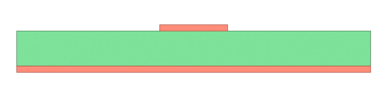
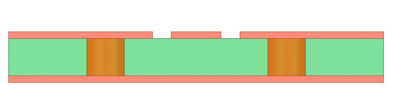
Fig. 5: Cross-section through the geometry of the microstrip conductor (A) and the coplanar conductor (B) used in the simulation
Microstrip conductor
A design for a 50 Ω microstrip conductor with a length of 1 mm was selected. A layered structure with the Panasonic Megtron 6 material (as before) and an 18 µm thick Cu layer on both sides was simulated. In contrast to the uncoated material sample, two separate effects are now considered in the simulation of ageing.
On the one hand, the material degradation leads to a higher field dissipation in the dielectric. Figure 6 shows a simulation with Ansys HFSS based on the data determined during the material tests and the associated increased field losses.
 Fig. 6: S-parameters of a 1 mm microstrip line at 79 GHz. The circles show the transmission and the squares the reflection. The data for 85 °C/85 % RH have been omitted for reasons of clarity
On the other hand, the change in the dielectric constant leads to a change in impedance - albeit only a slight one - and thus to a mismatch between the microstrip line and the neighboring areas of the signal routing and the signal coupling.
Coplanar line
As another typical representative of RF components, a design for a 50 Ω coplanar line with a length of 1 mm was simulated in the same described layer arrangement. Figure 7 shows the results of the HFSS simulation accordingly. As with the microstrip conductor, the increased losses have a considerable influence on the signal transmission. The change in the dielectric constant also leads to a result comparable to that of the microstrip conductor(Fig. 8).
 Fig. 7: S-parameters of a 1 mm coplanar line at 79 GHz. The circles show the transmission, the squares the reflection. The data for 85 °C/85 % RH have been omitted for reasons of clarity
 Fig. 8: Relative change in impedance for the lines shown in Figures 6 and 7. The data for 85 °C/85 % RH have been omitted for reasons of clarity
In all cases, the dielectric properties were assigned homogeneously to the entire substrate for the simulation. It remains to be investigated experimentally whether the oxidation process assumed for the changes has a homogeneous effect on the substrate or whether an inhomogeneous degradation profile is formed as a result of the structured metal coating, since the isolation of the polymer located under a metal layer from the oxidative attack may lead to delayed degradation. However, the highest degree of oxidation is still to be expected in the high-field areas of the cables that are relevant for performance.
|
Parameters |
Dimension (mm) |
|
Lsub |
3,5 |
|
Wsub |
3,5 |
|
Lpatch |
0,94 |
|
Wpatch |
1,22 |
|
Linset |
0,3 |
|
Winset |
0,1 |
|
h |
0,1 |
Patch antenna
To illustrate how the variations in electromagnetic properties affect the performance of antennas for 79 GHz radar applications, a patch antenna geometry with a single feed point was considered. The structure is similar to the transmission lines mentioned above (see Fig. 9). The antenna design was designed for a resonant frequency of 79 GHz, using the material properties of the unaged Megtron 6 substrate material for simulation (er: 3.8 and tand: 0.008). The dimensions of the simulated antenna are listed in Table 2.
 Fig. 9: Oblique view and side view of the simulated patch antenna at 79 GHz fed by a feed point
The simulated reflection coefficient and radiation pattern of the antenna at a frequency of 79 GHz are shown in Figures 10 and 11. The antenna has an impedance bandwidth of 2.21 GHz, a maximum antenna gain in the main radiation direction of 6.34 dBi and an efficiency of 72 %.
 Fig. 10: Simulated reflection coefficient of the patch antenna
 und H-Feldebene (rot)") Fig. 11: Simulated radiation pattern of the patch antenna around the resonant frequency of 79 GHz; E (blue) and H (red) field planes
Fig. 11: Simulated radiation pattern of the patch antenna around the resonant frequency of 79 GHz; E (blue) and H (red) field planes
In the subsequent simulation step, the aged antenna is then simulated by changing the dielectric constant of the substrate and the loss angle according to the results of the material characterization after accelerated aging. For all variations of the material properties considered, the radiation pattern of the antenna changes, the peak value of the reflection coefficient remains below -20 dB. Figures 12 and 13 show the corresponding changes in the resonant frequency, the impedance bandwidth, the antenna gain and the efficiency at 79 GHz.
For example, the resonant frequency of the antenna shifts significantly towards lower frequencies due to the sharp increase in the dielectric constant as the material ages at a temperature of 150 °C. With an ageing period > 1500 hours, the measured material values lead to a drift away from the operating bandwidth of 76.5 GHz to 81 GHz targeted for radar applications.
 und Antenneneffizienz (Quadrate) einer einzelnen Patch-Antenne bei 79 GHz über den Alterungsprozess (Rot: 150 °C, Blau: Therm. Zylken); (Daten aus der Auslagerung bei 85 °C/ 85 % RH sind der Übersichtlichkeit halber weggelassen)") Fig. 12: Antenna gain (circles) and antenna efficiency (squares) of a single patch antenna at 79 GHz over the ageing process (red: 150 °C, blue: thermal cycles); (data from aging at 85 °C/ 85 % RH are omitted for the sake of clarity)
Fig. 12: Antenna gain (circles) and antenna efficiency (squares) of a single patch antenna at 79 GHz over the ageing process (red: 150 °C, blue: thermal cycles); (data from aging at 85 °C/ 85 % RH are omitted for the sake of clarity)
 und und Impedanzbandbreite (Quadrate) einer einzelnen Patch-Antenne bei 79 GHz über den Alterungsprozess (Rot: 150 °C, Blau: Therm. Zylken); (Daten aus der Auslagerung bei 85 °C/ 85 % RH sind der Übersichtlichkeit halber weggelassen)") Fig. 13: Resonant frequency (circles) and impedance bandwidth (squares) of a single patch antenna at 79 GHz over the aging process (red: 150 °C, blue: thermal cycles); (data from aging at 85 °C/ 85 % RH are omitted for clarity)
Fig. 13: Resonant frequency (circles) and impedance bandwidth (squares) of a single patch antenna at 79 GHz over the aging process (red: 150 °C, blue: thermal cycles); (data from aging at 85 °C/ 85 % RH are omitted for clarity)
In contrast, the increase in the loss angle at 150 °C not only compensates for the reduction in bandwidth due to the higher er, but actually leads to an increased impedance bandwidth for all ageing steps. The frequency shift and the increase of the loss angle also lead to a strong reduction of the maximum bandwidth and the antenna efficiency at the center frequency of 79 GHz.
The same effects - i.e. the shift in resonant frequency, the increase in impedance bandwidth and the reduction in maximum gain and efficiency - occur when the material is subjected to thermal cycling between -55 °C and 150 °C. In this case, the changes compared to thermal cycling are not significant. Here, the changes compared to thermal storage are not as significant, as the increase in the dielectric constant and the loss angle are significantly lower than with long-term ageing @ 150 °C.
The performance of the antenna is not affected by storage at 85 °C/85 % relative humidity, since - as seen - the corresponding changes in the material properties are negligible.
Summary & outlook
- The dielectric properties of the RF laminate investigated in this work are very sensitive to accelerated ageing. In particular, storage at 150 °C leads to a 9 % increase in the dielectric constant, and the losses more than doubled over the aging period (2000 hours). A saturation effect was not observed. It is assumed that thermal oxidation of the polymer matrix is the cause of this effect.
- Ageing under thermal cycles led to a similar trend, but to a lesser extent in the thermal budget.
- In contrast, storage at 85 °C and 85 % relative humidity showed no significant change in parameters.
- It seems obvious that it is primarily the oxidative ageing behavior of the polymer that leads to the changes in properties.
- The increased dielectric constant and the poorer loss factors directly impair the transmission of HF signals. In the extreme case (ageing at 150 °C), it has been shown that the transmission efficiency of a microstrip line decreases by a factor of about two and the reflection increases due to the mismatch introduced. The example of an earthed coplanar line showed a comparable deterioration.
- For the patch antenna, the changed properties led to a shift in the resonant frequency towards lower frequencies, resulting in a sharp drop in gain and efficiency compared to the design frequency. The simulations showed that the antenna no longer met the specifications even after a comparatively short storage time at 150 °C.
The ageing study has shown the great influence that the stresses occurring during operation can have on the performance of an RF laminate-based vehicle radar system. Future investigations will show whether the effect is comparable for other laminates and other substrate thicknesses.
The effects on other types of transmission lines and components also need to be evaluated. Strategies to mitigate the effect will also be investigated.
Possible beneficial effects of a flat metallization to reduce the oxidation progress into the material and thus to mitigate the aging effects are also the subject of future investigations.
Author info:
Julia-Marie Köszegi (Research Focus Microperipheric Technologies, Technische Universität Berlin, Berlin, Germany,
Marco Rossi, Olaf Wittler, Hans Walter, Oliver Schwanitz, Ivan Ndip, Klaus-Dieter Lang, Martin Schneider-Ramelow. RF & Smart Sensor Systems, Fraunhofer Institute for Reliability and Microintegration, Berlin, Germany;
References:
[1] A. Ziebinski; R. Cupeka; D. Grzechcab; L. Chruszczykb: Review of advanced driver assistance systems (ADAS), AIP Conference Proceedings. Vol. 1906. no. 1. AIP Publishing LLC, 2017, p. 120002
[2] J. Dieckmann et al: Automotive radar the key technology for autonomous driving: From detection and ranging to environmental understanding, 2016 IEEE Radar Conference (RadarConf). IEEE, 2016, pp. 1-6
[3] P.D.T. O'Connor; A. Kleyner: Practical Reliability Engineering, 5th Edition, Chichester, Wiley, 2012, p 1
[4] J. H.L. Pang; T.H. Low; B.S. Xiong; F. Che: Design for reliability (DFR) methodology for electronic packaging assemblies, Proceedings of the 5th Electronics Packaging Technology Conference (EPTC 2003), 2003, pp. 470-478
[5] O. Wittler; A.M. Nejadari; B. Michel: Detection of degradation in die-attach materials by in-situ monitoring of thermal properties, 2009 11th Electronics Packaging Technology Conference, 2009, pp. 153-157
[6] L.-F. Chen; C. K. Ong; C.P. Neo; V.V. Varadan; V.K. Varadan: Microwave electronics: Measurement and Materials characterization, John Wiley & Sons, 2004
[7] T. Braun et al: Fan-out wafer level packaging for 5G and mm-Wave applications, 2018 International Conference on Electronics Packaging and iMAPS All Asia Conference (ICEP-IAAC). IEEE, 2018, pp. 247-251
[8] A. Kanitkar et al: Fork-Coupled Resonators for Characterization of Mold Material for 5G Applications, 2020 23rd International Microwave and Radar Conference (MIKON), IEEE, 2020, pp. 177-180
[9] M.C. Lanca; C.J. Dias; D.D. Gupta; J. Marat-Mendes: Comparative study of dielectric relaxation spectra of electrically and thermally aged low density polyethylene, 2003 Annual Report Conference on Electrical Insulation and Dielectric Phenomena, IEEE, 2003, pp. 161-164
[10] C. Guillermin; P. Rain; S.W. Rowe: Characterization of electrothermal aging of a filled epoxy resin, Proceedings of the 2004 IEEE International Conference on Solid Dielectrics, IEEE, 2004, pp. 351-354
[11] C. Kim; Z. Jin; P. Jiang; Z. Zhu; G. Wang: Investigation of dielectric behavior of thermally aged XLPE cable in the high-frequency range, Polymer testing, 25(4), 2006, pp. 553-561
[12] J.C. Pandey; N. Gupta: Thermal aging assessment of epoxy-based nanocomposites by space charge and conduction current measurements, 2014 IEEE Electrical Insulation Conference, IEEE, 2014, pp. 59-63
