Plasma quenching for the formation of nanoparticles uses a cyclical increase in the prevailing pressure in the vacuum chamber in sputtering processes. In the case of carbon (C), a significant reduction in the coefficients of friction on various substrates was achieved using a typical industrial magnetron sputtering system and cathode sputtering. While Part 1 presented preliminary considerations and some of the experiments, Part 2 supplemented the experimental implementation and then focused on the resulting findings. Finally, discussion and conclusions from the experiments follow.
Continuation of the results and discussion
... In the next step, some process parameters that are expected to yield higher C contents were used for the development of plasma quenching. In the literature, the use of He pressure surges is described for this purpose, while the approach chosen here does not use a change in gas flows but the cyclic increase in the prevailing total gas pressure by reducing the suction power of the high vacuum pump by partially closing the VAT vacuum slider. A total of 32 such pressure surges were applied to each of the ~4 µm layer thicknesses achieved (i.e. bilayer thickness ~120 nm). The final pressures achieved can be seen in Table 2, which also shows the chemical compositions and roughnesses achieved.
 Table 2: Chemical composition and roughness of coatings produced using 45 sccm Ar + 5 sccm C2H2 (initial pressure during sputtering: 3.7x10⁻³ mbar at 100 % opening of the VAT slide, cycle time for sputtering: 5 min) and different VAT slide positions used in the plasma quenching cycle (time: 1 min) and the resulting chamber pressures. Total number of cycles: 32
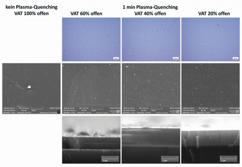 Fig. 5: Light microscopic (top row) and SEM images (middle row) of the surface topography as a function of the plasma quenching parameters. Bottom row: SEM images of fracture surfaces with developed microstructure of the layers and microtopography forming on the surfaceThefurther the VAT slider is closed, the higher pressures can be achieved through this resistance in the gas flow to the high vacuum pump. Closing from a fully open state (pressure ~3.1x10⁻³ mbar) to a VAT slide that is only 20 % open increases the pressure by a factor of 4. The chemical analysis shows that when sputtering from the MoS2 target, the C content decreases slightly, but the Mo and S contents hardly change. This makes the dissociation of C2H2 more difficult at higher pressures, as reflected by the results with even lower C content at 40 and 20% VAT opening. In addition, even compared to the coatings without plasma quenching (see earlier), ~5 times the flux of C2H2 is required to achieve similar carbon content in the coating (~40%) at comparable sputtering conditions. The longer sputtering time (about 22 % longer for the 20 % open variant) and thus lower deposition rates (in the range of about 12 nm/min) also prove this. In addition, however, the lower pumping rates due to the VAT valve show increases in the impurities during the quenching phase. Mainly oxygen can be detected, whereby the H content cannot be taken into account due to measurement limitations. The O content is most likely not caused by leaks in the system, but by the splitting of H2Omolecules, which are deposited on all inner surfaces of the recipient by absorption, e.g. during charging. The low coating temperature of max. 65-70 °C on the substrates or << 40 °C of the chamber prevents efficient evaporation during evacuation and favors the incorporation of OH groups into the layer structure. The Mo:S ratio changes only slightly compared to the above results.
The roughness, on the other hand, increases significantly. The starting level on austenitic stainless steel is its own roughness Ra of < 0.01 µm, which is at least doubled or in some cases tripled by the layer deposition - especially in the area of the middle opening position of the VAT slide. Further increasing the chamber pressure (valve gate position 20 % open) leads to higher pressure, but has hardly any effect on the roughness. Ra and Rq are arithmetic and quadratic mean values, whereby the latter integrates roughness peaks significantly more strongly in the roughness values standardized with regard to measuring methods (EN 4287). Rp as the distance from the geometric center roughness to the profile peak height within the measuring section specifically takes individual peaks into account.
Rp values are very meaningful in the interpretation of light microscopic or SEM images, as can be seen in Figure 5. While hardly any defects can be found on the layer without plasma quenching (except for the flake, which was necessary for SEM focusing), the density of particles, especially those <1 µm in diameter, increases when the VAT vacuum valve is reduced to only 60 % opening. A further increase in particle density occurs at 40 % opening, while the density decreases again at 20 % opening in light microscopic and SEM images. The emerging growth structure of the MoS2-C coatings shows a layered structure in the fracture surface at 60 and 40 % aperture, which is not recognizable at 20 % aperture. All layers appear very amorphous. The surface of the images, which becomes more blurred as the image depth increases, can also be used to assess the three-dimensional shape and type of bonding of the particles forming on the growing coating surface. This is either round and larger or small and more angular. In many cases, these also extend into the growing layer. Round particles indicate droplets coming from the MoS2 target (in some cases superficial melting of the target when the energy input is too high, as can occur at the beginning of the pressure increase, for example). This is confirmed by the EDX surface analysis in Figure 5: The microparticles that appear brighter have significantly lower blue tones than the surroundings, whereby these blue tones were assigned to the analyzed carbon (Fig. 6). Based on experience, small particles with a partly angular structure are predominantly carbon submicro- or nanoparticles formed in the plasma, which mainly form carbon surface structures (due to the hexagonal, planar graphite structure).
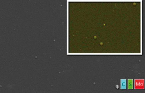 Fig. 6: SEM detailed view of the layer surface of a plasma quenching parameter set with 60 % VAT opening and EDX surface analysis with color assignment of the concentrations of C, S and Mo
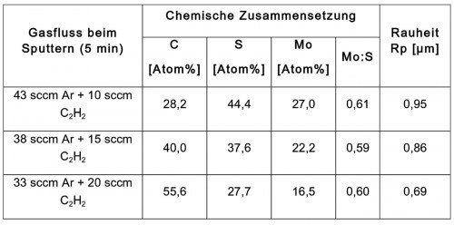 Tab. 3: Chemical composition, deposition rates and roughness of coatings produced using different C2H2 fractions in the sputtering gas flow at 40 % opening of the VAT slider for 1 min (chamber pressure ~5.6x10⁻³ mbar) between 5 min sputtering cycles
As the coating rates are too low for future industrial use and at the same time the substrate temperatures are well below the permissible substrate temperatures for coating PA12, the sputtering power was doubled in the next step (2000 W on the MoS2 targets). In addition, the optimum 40% opening of the VAT slide in terms of particle formation was used and the influence of higherC2H2concentrations(C2H2flowsof 10, 15 and 20 sccm) in the sputtering atmosphere was investigated (Table 3). This led to an increase in the deposition rate to 22.5 nm/min. Compared to the lower sputtering performance andC2H2gasflows, a significantly lower proportion of carbon is now separated at the lowestC2H2 flowvariant investigated here (10 sccm). At 15 sccm, the C content in the layer is comparable and only at 20 sccm C2H2 is it significantly higher. The C content correlates almost linearly over the entireC2H2flowrangeinvestigated. A comparison with the chemical composition in layers not produced with pressure surges (i.e. without plasma quenching) shows a significantly lower C content - at twice the sputtering power (as an additional difference), the C content is only around 50 %, while the MoS2 content is higher.
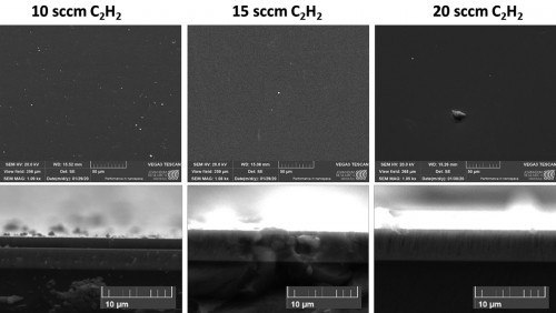 Fig. 7: SEM images of the surface topography as a function of the plasma quenching parameters (top row). SEM images of fracture surfaces with formed microstructure of the layers and microtopography forming on the surface (bottom row)
The roughness Rp decreases with increasing carbon content in the layers - as does the particle density. This can be seen very clearly in the SEM images in Figure 7. The particles on the surface, but also the particles incorporated in the layer in the fracture surface images, become fewer with increasing carbon content, but larger. The majority of the small particles are not round but angular, which indicates carbon particles. The larger particles, on the other hand, have a higher MoS2 content.
 Fig. 8: Coefficient of friction and penetration depth in the coatings deposited in different C2H2 atmospheres with 1 min plasma quenching (40 % VAT opening) per 5 min sputtering
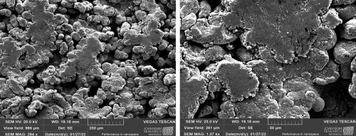 Fig. 9: SEM analyses of the coating deposited on PA12 at 10 sccm C2H2 using plasma quenching (1 mi per 5 min sputtering) after 1000 linear tribology cycles
The tribological investigations show only a very slight increase in the coefficients of friction from 0.15 to 0.18 with increasingC2H2flow on a slightly yielding austenite substrate. The penetration of the 6 mm Al2O3 ball is only very slight. Of interest are the > 25 % lower coefficients of friction than in the coatings without plasma quenching - even taking into account the same C content of the coating. This means that the increased formation of carbon particles in the coating leads to significantly improved sliding. Similar low coefficients of friction (0.15 to 0.17) are also evident for the 10 sccm C2H2coatingon PA12 - even despite the high SLS-induced roughness with clearly visible powder grains (see Fig. 9 on the wear tests). The increase over the entire number of cycles is also only slight and there is no approximation to 0.30-0.35 of uncoated PA12. However, the penetration depth tends to be significantly greater than with austenite. The evaluation of the wear surfaces shows significantly less disruption of the PA12 in the contact surface of the PA12 grains, i.e. the density of the dark crack areas is very low. The surface of the coated PA12 grains has an almost similar color to the surrounding coated PA12 surface. This indicates similar surface chemistry, i.e. transfer layers transferred to the friction surface. These reduce friction by 35-50% compared to contact with uncoated PA12.
Finally, the optimum coating, i.e. 10 sccm C2H2 at 2 kW power and 40 % VAT opening during plasma quenching, was used to coat helical gears with optimized lightweight geometry between the axle and teeth, as shown in the figure on p. 816.
Summary
The results comparing the sputtering of MoS2 under homogeneous gas pressure conditions (C2H2flow) during the entire sputtering time and using pressure impacts (plasma quenching) showed clear influences on the frictional behavior with the same carbon content in the layers. Topography and structural investigations indicate a high content of very fine carbon particles under coating conditions similar to industrial conditions. These have a very good lubricating effect and reduce the coefficient of friction by > 25 %. Especially on PA12 from SLS production with a very rough sintered surface with many individual grains with point contact, the coefficient of friction hardly increases after the removal of the roughness peaks - i.e. under the test conditions presented with significant overloading of the polymer, especially in point contact, it does not reach the > 0.30 Plasma quenching is therefore a very useful concept, especially for established sputtering technology and systems, to minimize the friction and wear of very low-friction layers simply by changing the vacuum pusher (or the pump suction power). Thermoplastics such as PA12 with only low temperature resistance can be coated without any problems.
Acknowledgments:
The work was funded by the "fun-3d-manu" project of the Österreichische Forschungsförderungsgesellschaft mbH. Thanks also go to the Province of Styria, the EU and its ERDF regional funding programs.
Special thanks go to the project partners PCCL, Rapid Product Development GmbH (RPD), Rübig GmbH & Co KG, Sinus Pro and Xentis.
Literature
[1] Bonnin, X; Lombardi, G; Hassouni, K; Michau, A; Bénédic, F; Arnas, C.: Modelling of carbon dust formation by cluster growth in argon plasmas, J Nucl Mater 2007, 363-365, 1190-4
[2] Donnet, C.; Erdemir, A.: Historical developments and new trends in tribological and solid lubricant Coatings, Surf. Coat. Technol., 180-181, (2004), 76-84
[3] Erdemir, A.: Handbook of Modern Tribology, (ed. B. Bhushan), Solid Lubricants and Self-lubricating Films, Boca Raton, FL: CRC Press, (2001), 787-818
[4] Hegemann, D.; Hanselmann, B.; Blanchard, N.; Amberg, M.: Plasma - Substrate Interaction during Plasma Deposition on Polymers, Contributions to Plasma Physics, 54(2014)2, 162-169
[5] Kot, M.: Contact mechanics of coating-substrate systems: Monolayer and multilayer coatings. archives of civil and mechanical engineering, 12(2012)4, 464-470
[6] Lackner, J.M.; Waldhauser, W.; Major, B.; Major, L.; Kot, M.: Plastic deformation in nano- scale multilayer materials - A biomimetic approach based on nacre, Thin Solid Films, 534, 2013, 417-425
[7] Lackner, J.M.; Waldhauser, W.; Ganser, C.; Teichert, C.; Kot, M.; Major, L.: Mechanisms of topography formation of magnetron-sputtered chromium-based coatings on epoxy polymer composites, Surface and Coatings Technology, 241, 2014, 80-85
[8] Levy, G.N.: Total quality management for rapid manufacturing, Proc. Euro-uRapid Frankfurt: A5-1, 2006
[9] Polcar, T.; Gustavsson, F.; Thersleff, T.; Jacobson, S.; Cavaleiro, A.: Complex frictional analysis of self-lubricant W-S-C/Cr coating, Faraday Discussions, 156 (2012), 383-401
[10] Povilus, A.P.; Wurden, C.J.; Vendeiro, Z.; Baquero-Ruiz, M.; Fajans, J.: Vacuum compatibility of 3D-printed materials. Journal of Vacuum Science & Technology A, 32(2014)3, 033001
[11] Robertson, J.: Amorphus and non-crystalline Carbons, in: P. Delhaes (Ed.), Graphite and Precursors, Gordon and breach science publishers, The Netherlands, 2001
[12] Schmid, M.; Simon, C.; Levy, G.N.: Finishing of SLS-parts for rapid manufacturing (RM) - a comprehensive approach. Proceedings SFF,2009, 1-10
[13] Scharf, T.W.; Prasad, S.V.: Solid lubricants: A review, J. Mater. Sci. 48 (2013), 511-531
[14] Stueber, M.; Holleck, H.; Leiste, H.; Seemann, K.; Ulrich, S.; Ziebert, C.; Journal of Alloys and Compounds 483 (2009) 321
[15] Tay, F.E.; Haider, E.A.: Laser sintered rapid tools with improved surface finish and strength using plating technology, Journal of Materials Processing Technology, 121(2002)2, 318-322
[16] Thirumalai, S.; Hausberger, A.; Lackner, J.M.; Waldhauser, W.; Schwarz, T.: Effect of the type of elastomeric substrate on the microstructural, surface and tribological characteristics of diamond-like carbon (DLC) coatings, Surface and Coatings Technology, 302, 2016, 244-254
[17] Thirumalai, S.; Hausberger, A.; Lackner, J.M.; Waldhauser, W.; Schwarz, T.: Anode layer source plasma-assisted hybrid deposition and characterization of diamond-like carbon coatings deposited on flexible substrates. Thin Solid Films, 655, 2018, 54-61
[18] Tomastik, C.; Lackner, J.M.; Pauschitz, A.; Roy, M.: Structural, chemical and nanomechanical investigations of SiC/polymeric aC: H films deposited by reactive RF unbalanced magnetron sputtering, Solid State Sciences, 53, 2016, 1-8
[19] Vriendt, V.D.; Maseri, F.; Nonet, A.; Lucas, S.: Study of nanoparticles formation in a pulsed magnetron discharge in acetylene, Plasma Process. Polym. 6 (2009) S6-S10
[20] Zia, A.W.; Zhou, Z.; Li, L.K.Y.: A preliminary wear studies of isolated carbon particles embedded diamond-like carbon coatings, Tribology International, 114, 2017, 42-47
[21] Zia, A.W.; Zhou, Z.; Li, L.K.Y.: A new approach to create isolated carbon particles by sputtering: A detailed parametric study and a concept of carbon particles embedded carbon coatings, Diamond and Related Materials, 76, 2017, 97-107


