
Cutting tools are subject to particularly high stresses in the cutting edge area. For this reason, wear protection coatings have been applied to protect the edges for decades. The stability of a coated edge depends on its specific geometry, the roughness, the material to be machined and the coating system to be applied. This work deals with the investigation of AlCrN-based multilayer coating systems and cathodic vacuum arc coating processes, which enable a reduction of the cutting edge radius during coating deposition. This should make it possible in the future to take higher initial radii into account when selecting tools and to offer coating solutions that meet requirements with a freely adjustable edge geometry.
4 Geometric analysis of selected geometries
 Fig. 9: Principle sketch of a cutting edge with specification of the cutting edge radius rK and the wedge angle βCuttingedges and wedge angles(Fig. 9) were precisely measured using the Alicona Infinite Focus 4G optical 3D measuring system from Alicona.
The results are illustrated in Figures 10 and 11 . While the cutting edge radius approximately triples (for initial radii of 5 µm) or doubles (initial radius of 10 µm) compared to the uncoated initial sample without the presence of a bias voltage, the cutting edge radius can be significantly reduced for coatings with bias voltages (-500 V and 900 V). In the case of initial radii of 10 or 15 µm, the initial edge radius can be halved. With output radii of 5 µm, the cutting edge radius is hardly affected.
In addition to the cutting edge radius, the wedge angle of the cutting edge is an important output variable in machining technology. The graph(Fig. 11) shows that the wedge angle generally increases regardless of the coating parameters and the initial cutting edge radius. However, the effect decreases slightly with increasing bias stress. For the cutting edge, this means that the wedge angle is increased by the coating, but the cutting edge radius can be reduced.
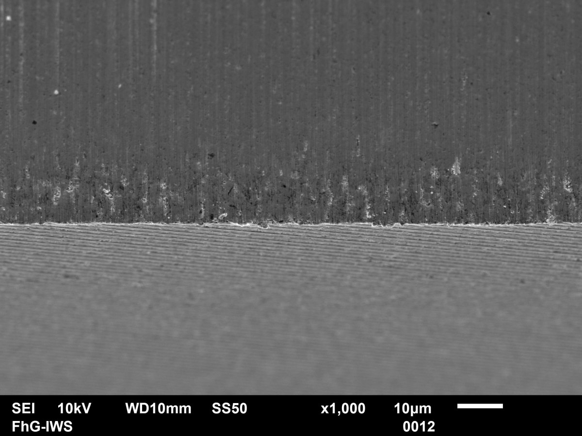
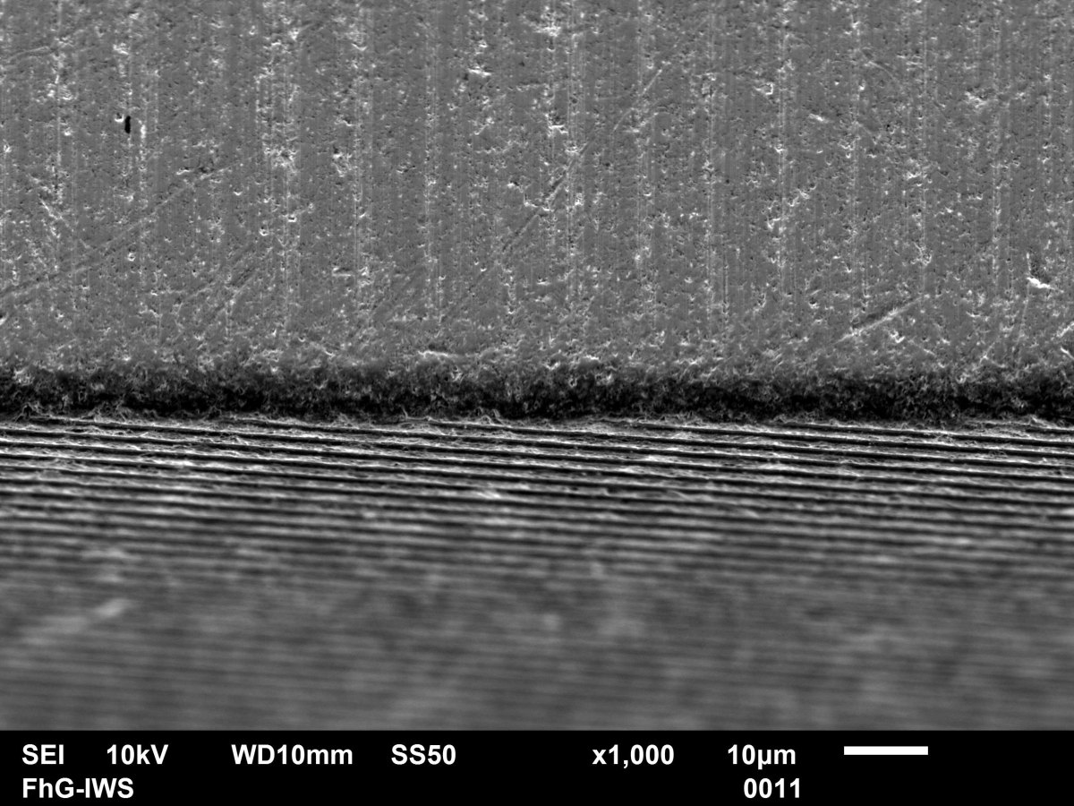
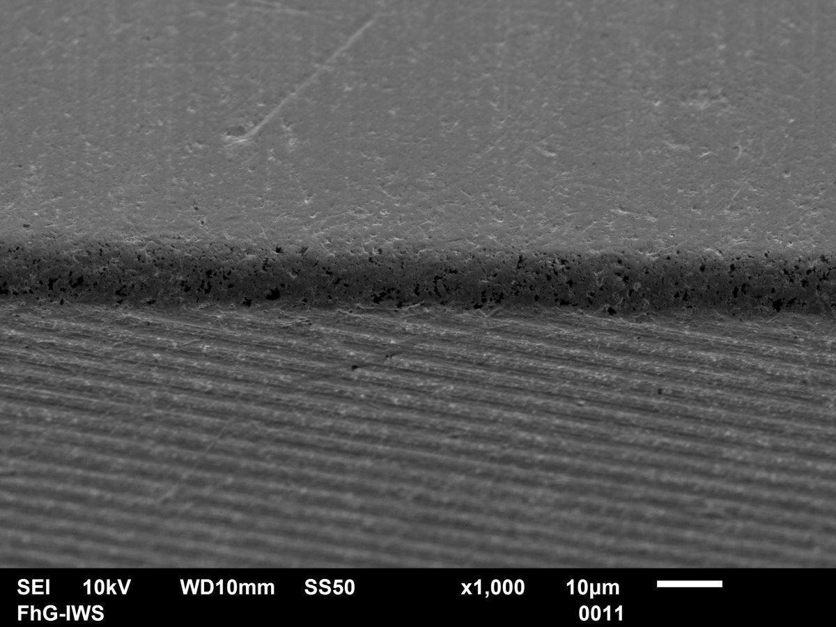
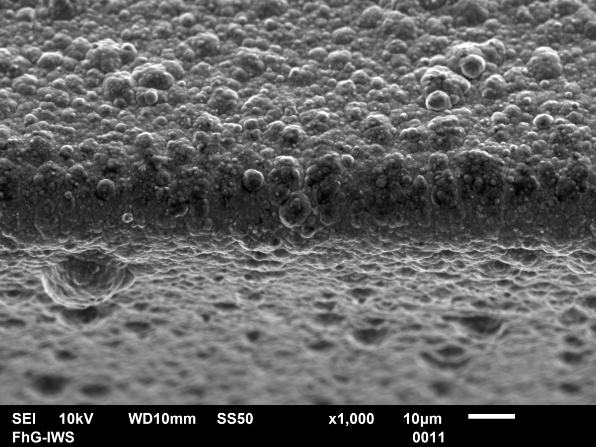
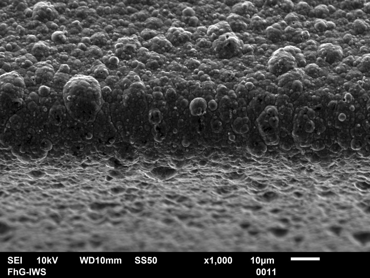
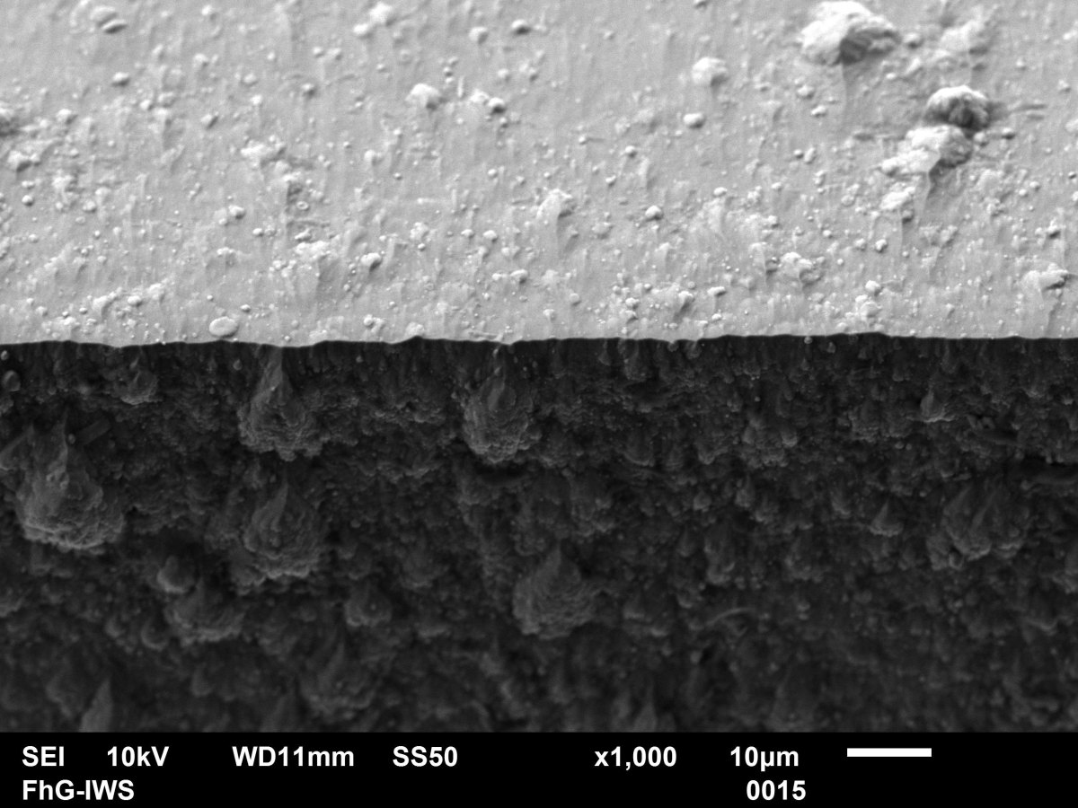
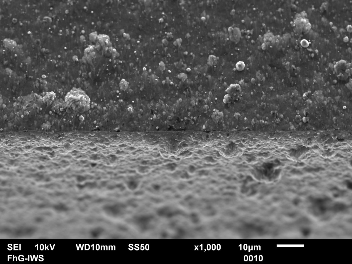
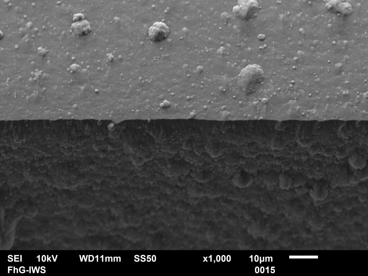
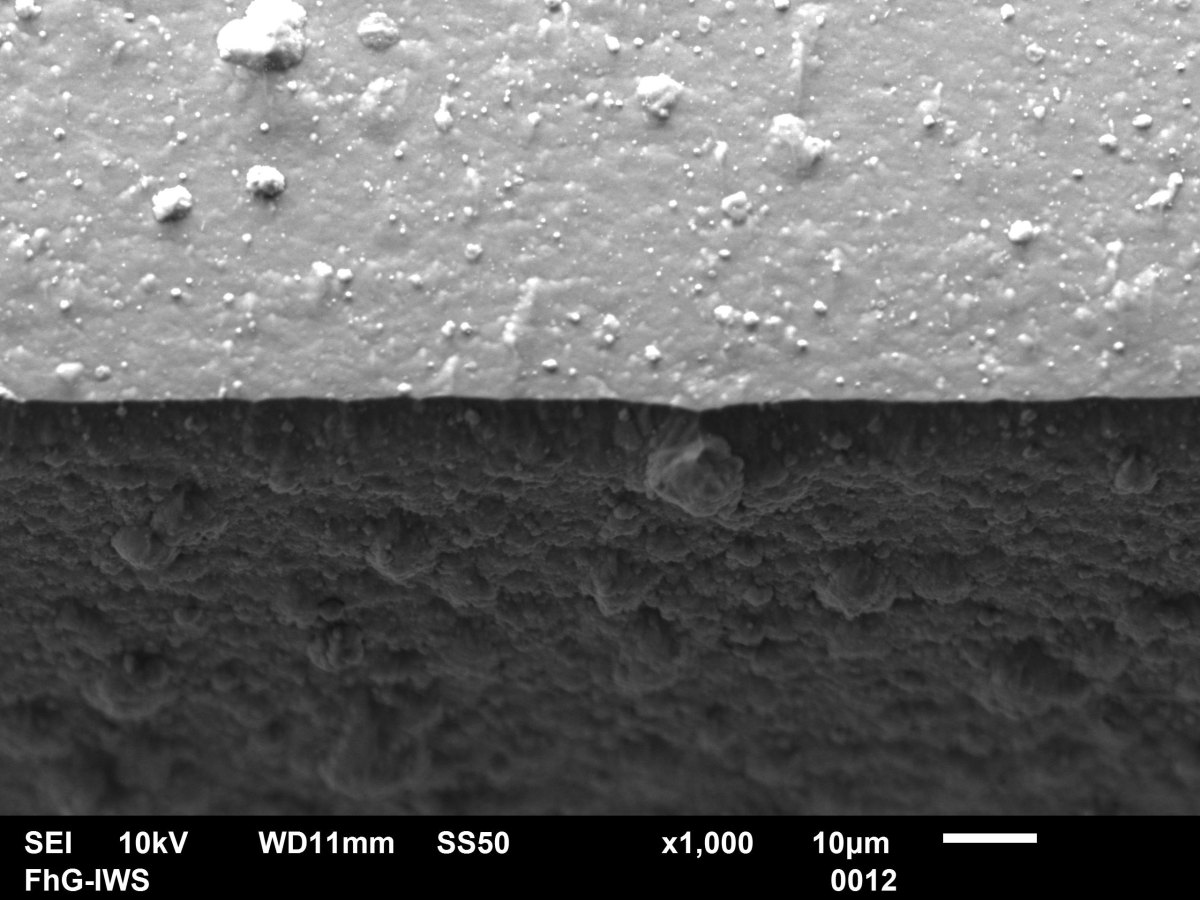
SEM images(Table 5) are used to illustrate the coating morphology that forms in the edge area as a function of the initial edge radius and the applied bias voltage.
With the help of the figures, it is also possible to understand why the error intervals when measuring the cutting edge radii are larger, especially for the initial cutting edges and for the coating with 0 V bias compared to the coatings with higher bias voltage. The initial condition still exhibits the machining roughness or grinding marks, while the coating with 0 V bias has a particularly high particle load on the cutting edge. With increasing bias voltage, a smoothing or leveling effect comes into play to sharpen the cutting edges, which leads to an overall better edge quality.
") Fig. 10: Cutting edge radius before and after coating as a function of the initial radius and the bias voltage (nominally the same coating thickness at the respective bias voltage)
Fig. 10: Cutting edge radius before and after coating as a function of the initial radius and the bias voltage (nominally the same coating thickness at the respective bias voltage)
 Fig. 11: Wedge angle before and after coating as a function of the initial radius and the bias voltage
| Initial edge radius 5 μm | Initial edge radius 10 μm | Initial edge radius 15 μm |
| uncoated | uncoated | uncoated |
 |
 |
 |
| coated with 0 V bias | coated with 0 V bias | coated with 0 V bias |
 |
 |
 |
| coated with -500 V bias | coated with -500 V bias | coated with -500 V bias |
 |
 |
 |
| coated with -900 V bias | coated with -900 V bias | coated with -900 V bias |
 |
 |
 |
5 Hardness and modulus of elasticity
Hardness and modulus of elasticity are important parameters that describe the mechanical behavior of the coatings. A high hardness is desirable in order to achieve the highest possible protective effect. The modulus of elasticity, on the other hand, describes the resistance to elastic deformation - the higher the value, the higher the resistance to deformation. The investigated coatings were characterized by means of the nanoindentation test. It was found that hardness and modulus of elasticity can be varied depending on key process parameters such as bias voltage and process gas pressure. This makes it possible to adjust the properties of the coatings to the desired values. Figures 12 and 13 show the hardness and modulus of elasticity curves for different coatings.
 Fig. 12: Dependence of the layer hardness on the negative bias voltage applied to the substrate
Fig. 13: Dependence of the Young's modulus on the negative bias voltage applied to the substrate
Compared to the hardness curves of monolayer coating systems (AlCrN), those of multilayer coatings (AlCrSiN/TiN) are significantly flatter. It can be seen that the change in mechanical properties is relatively moderate with multilayer coatings despite increasing bias stress. This has the advantage that the properties of the layer do not differ too much from the areas where the field strength is not increased or even decreased (depressions/holes) at points where the electric field is locally increased (e.g. at edges). This equalizing effect can be enhanced by varying the coating pressure. The lower the pressure (compare 5 Pa to 2 Pa), the more uniform the curves of hardness and modulus of elasticity over the bias stress.
6 Challenges in edge coating
 Fig. 14: Coated edge with an initial radius of 15 µm, coated with an AlCrSiN monolayer at a nitrogen pressure of 5 Pa and a bias voltage of -500 VIn addition tothe coatability of curved areas, as in the case of the tool cutting edge, there is always the question of the integrity of the coating in this area. Due to the stress concentration at the tips (so-called wedge effect), tool edges are a potential starting point for cracks, which in the worst case can lead to the destruction of the coating. This effect is illustrated in Figures 14 and 15.
6.1 Monolayers
Monolayer coatings, such as AlCrSiN, shown in Figure 14, are particularly susceptible to spalling and coating failure at high bias stresses. This effect prevents the use of this type of coating or limits its application to low, negative bias voltages of up to around 100 V, low coating thicknesses and less pointed geometries.
6.2 Multilayers
Compared to monolithic coating systems, multilayer coating systems are significantly more resistant and also allow significantly higher bias voltages during coating deposition. On the one hand, there is a leveling of layer growth defects(Fig. 15, left, circle) compared to layers that grow without bias stress(Fig. 15, right, arrows). On the other hand, the formation of cracks(Fig. 15, left) is possible due to a high stress concentration in the edge area caused by residual stresses in the coating.
Edge preparation prior to coating is a work step that has already been tried and tested in industry [17]. The aim here is to improve the quality of the uncoated edges and the subsequent coating by means of targeted edge preparation.
A larger edge radius leads to a smaller wedge effect and can, however, be reduced again by the coating processes developed in the course of this work. In the future, further investigations and coating developments should lead to an industrially applicable coating solution that allows the edge geometry to be specifically adjusted during the coating process.
 Fig. 15a: Growing a sharp edge
 Fig. 15b: Growing a rounded edge
7 Summary and outlook
In this study, new approaches for the coating of tools based on AlCrSiN/TiN coatings were generated and tested using arc PVD processes for coating cutting edges, improving edge coverage and reducing the radius at the cutting edge. The investigation of the reduction effect for the AlCrSiN/TiN system resulted from preliminary tests at the TU Dresden and the Fraunhofer IWS. A multi-layer coating system was used in the development of the coating processes. The coating of complex geometries (e.g. edges) with the developed layers is possible with process reliability, even despite increased bias stress. The reason for this remarkable behavior compared to monolithic coating systems is due to a special deposition characteristic of the coating system used, a pronounced layering, the chemical composition and the associated phase formation and a presumably occurring ion etching. By using the coating system described and the deposition processes developed in the project, a significant reduction in the cutting edge radius and a final radius that can be adjusted by the coating are possible. In the future, industrially applicable coatings should be available which, in addition to the edge geometry that can be specifically adjusted by the coating process, also exhibit particularly high stability.
Acknowledgements
This work was financially supported by the German Research Foundation (DFG) as part of the project with the funding code LE 1373/25-1. We would like to take this opportunity to thank the staff involved from the Fraunhofer IWS and the Chair of Materials Engineering at the TU Dresden. In addition, many dedicated students have made important contributions with their student research projects, diploma and master's theses.
Literature
- Johansson, B.O. et al.: Influence of substrate shape on TiN films prepared by reactive sputtering, Thin Solid Films 111(1984) 313-322
- Rother, B. et al.: Characterization of TiN-coated high speed steel cutting edges by load- indentation measurements, Surface and Coatings Technology 79(1996) 225-230
- Rother, B. et al.: Property distribution on three-dimensionally shaped PVD-coated samples, Surface and Coatings Technology 97( 1997) 200-205
- Jehn, A.H. et al.: PVD coating of 3D parts studied with model samples, Surface and Coatings Technology 94-95, 1997, 232-236
- Kim, S.S. et al.: Deposition behaviors of CrN films on the edge area by cathodic arc plasma deposition process, Thin Solid Films 334 (1998) 133-139
- Novák R. et al.: Study of hard PVD coatings on strongly curved surfaces, Surface and Coatings Technology 114(1999) 65-69
- Macak, E.B. et al.: Electron microscopy studies of hard coatings deposited on sharp edges by combined cathodic arc/unbalanced magnetron PVD, Surface and Coatings Technology 151-152(2002) 349-354
- Macak, E.B. et al.: Edge related effects during ion assisted PVD on sharp edges and implications for coating of cutting tools, Surface Engineering 19(2003) 310-314
- Macak, E.B. et al.: Plasma-surface interaction at sharp edges and corners during ion-assisted physical vapor deposition, Part I: Edge-related effects and their influence on coating morphology and composition, J. Appl. Phys. 94(2003) 2829-2836
- Macak, E.B. et al.: Plasma-surface interaction at sharp edges and corners during ion-assisted physical vapor deposition, Part II: Enhancement of the edge-related effects at sharp corners, J. Appl. Phys. 94(2003) 2837-2844
- Flöter, A. et al.: Improving the sharpness of diamond-coated carbide blades, IDR 38(2004) 110-112
- Qin, F. et al.: Coating thickness effects on diamond coated cutting tools; Surface and Coatings Technology 204(2009) 1056-1060
- Sato, Y. et al.: Sharpening of CVD diamond coated tools by 0.5-10 keV Ar+ ion beam, Diamond and related Materials 20(2011) 954-959
- Bohlmark, J. et al.: Evaluation of Arc Evaporated Coatings on Rounded Surfaces and Sharp Edges, Materials Science Forum 681, (2011) 145-150
- Krülle, T. et al.: Nano-design for macrolayers, Vacuum in Research and Practice 30(2018) 46-49
- Watterson, P.A.: Child-Langmuir sheath structure around wedge-shaped cathodes, J. Phys. D: Appl. Phys. 22(1989) 1300-1307
- Tikal, F.: Cutting edge preparation - Aims, procedures and measurement methods, Kassel university Press GmbH, Kassel (2009)
