
Cutting tools are subject to particularly high stresses in the cutting edge area. For this reason, wear protection coatings have been applied to protect the edges for decades. The stability of a coated edge depends on its specific geometry, the roughness, the material to be machined and the coating system to be applied. This work deals with the investigation of AlCrN-based multilayer coating systems and cathodic vacuum arc coating processes, which enable a reduction of the cutting edge radius during coating deposition. This should make it possible in the future to take higher initial radii into account when selecting tools and to offer coating solutions that meet requirements with a freely adjustable edge geometry.
Tools for cutting applications are subject to particularly high loads in the area of the cutting edge. For this reason, wear protection layers have been applied to protect the edges for decades. The stability of a coated edge depends on parameters such as edge geometry, roughness, the material to be machined and the coating material system to be applied. This work deals with the investigation of AlCrN-based multilayer systems and cathodic arc coating processes, which allow a reduction of the cutting edge radius during the deposition process. Thus, it should be possible to consider higher starting radii when selecting tools and to offer coating solutions with a freely adjustable edge geometry.
1 Basics of plasma coating
![Abb. 1: Veranschaulichung der Beschichtungseffekte; links: geometrischer Effekt durch Abschattung der Sichtliniencharakteristik von PVD-Verfahren; rechts: Feldeffekt an spitzer Kante bei anliegender Biasspannung -UBias nach [7] und [16]](/images/stories/Redaktion_GT/Online-Artikel/Plasma_-_Neue_Ansätze_zur_Beschichtung_von_Werkzeugkanten/Abbildung-1.PNG "Abb. 1: Veranschaulichung der Beschichtungseffekte; links: geometrischer Effekt durch Abschattung der Sichtliniencharakteristik von PVD-Verfahren; rechts: Feldeffekt an spitzer Kante bei anliegender Biasspannung -UBias nach [7] und [16]") Fig. 1: Illustration of the coating effects; left: geometric effect due to shading of the line-of-sight characteristics of PVD processes; right: field effect at a pointed edge with bias voltage applied -UBias according to [7] and [16]The coating of complex geometries, such as those found in cutting tools of all kinds, continues to cause problems for coating suppliers. While the deposition of coatings on simple substrates, such as flat components, strips or cylinders, usually leads to a relatively homogeneous and uniform coating thickness distribution along the surface, the coating thickness distribution on angular, pointed or perforated surfaces is strongly dependent on the respective position on the sample surface. In addition to the line-of-sight characteristics of PVD processes (aspect ratio for holes, opening angle for gears, alignment of surfaces relative to the incident particle flow), influencing variables for such behavior are primarily determined by electric field and plasma properties.
Fig. 1: Illustration of the coating effects; left: geometric effect due to shading of the line-of-sight characteristics of PVD processes; right: field effect at a pointed edge with bias voltage applied -UBias according to [7] and [16]The coating of complex geometries, such as those found in cutting tools of all kinds, continues to cause problems for coating suppliers. While the deposition of coatings on simple substrates, such as flat components, strips or cylinders, usually leads to a relatively homogeneous and uniform coating thickness distribution along the surface, the coating thickness distribution on angular, pointed or perforated surfaces is strongly dependent on the respective position on the sample surface. In addition to the line-of-sight characteristics of PVD processes (aspect ratio for holes, opening angle for gears, alignment of surfaces relative to the incident particle flow), influencing variables for such behavior are primarily determined by electric field and plasma properties.1.1 Investigations into the influence of geometry
2 Experimental setup and characterization methods
![Abb. 2: Zonendiagramm: Darstellung der Kantenbedeckung in Abhängigkeit von der Biasspannung und dem Kantenwinkel [8–10]](/images/stories/Redaktion_GT/Online-Artikel/Plasma_-_Neue_Ansätze_zur_Beschichtung_von_Werkzeugkanten/Abbildung-2.PNG "Abb. 2: Zonendiagramm: Darstellung der Kantenbedeckung in Abhängigkeit von der Biasspannung und dem Kantenwinkel [8–10]") Fig. 2: Zone diagram: representation of the edge coverage as a function of the bias voltage and the edge angle [8-10]The process and coating development was carried out using the established DC vacuum arc technology (CAE) with an industrial coating system of type MR313 from Metaplas Ionon in Bergisch-Gladbach(Fig. 3). The coating system can be operated with two evaporators in parallel, whereby a magnetic field-controlled rectangular and a magnetic field-controlled round evaporator were used in this work (for further data, see Table 2).
Fig. 2: Zone diagram: representation of the edge coverage as a function of the bias voltage and the edge angle [8-10]The process and coating development was carried out using the established DC vacuum arc technology (CAE) with an industrial coating system of type MR313 from Metaplas Ionon in Bergisch-Gladbach(Fig. 3). The coating system can be operated with two evaporators in parallel, whereby a magnetic field-controlled rectangular and a magnetic field-controlled round evaporator were used in this work (for further data, see Table 2).| Coating system | The process | Dependencies and investigations | Reference |
| TiN | RMS | A layer thickness variation was carried out for bias voltages between -350 V and -500 V: here the TiN layer is missing at the edges, while at a bias voltage of -200 V a thin layer grows near the edges. Higher layer thicknesses occur at edges in the range from 32 V to -150 V, which can be attributed to a low sputtering yield. A higher Ar gas pressure (more impact processes between the particles in the chamber) weakens the edge effect, back-sputtering is suppressed and the layer thickness is hardly affected. | [1] |
| TiN | MS | Determination of geometry-dependent hardness curves. This involves the formation of denser and harder layers near the edges. The larger the edge angle, the harder the deposited layer becomes. | [2] |
| TiN | DMS + UBMS | Determination of geometry-dependent layer thickness distribution: the sharper the edge, the lower the layer thickness; the hardness increases towards the edge, the sharper the edge, the lower the hardness. | [3] |
| TiN | RMS, CAE, HCD | The coating thickness on edges decreases due to back-sputtering, it decreases with decreasing wedge angle. With CAE coating, a higher ionization of the plasma results in better depth coatability, a higher gas pressure leads to a higher coating thickness at the edge; the hardness at edges is lower than on the flat sample. Furthermore, the coatability of edges with edge angles of 30°, 54° and 90° and indentations is analyzed. Compared to other coating processes, CAE provided the highest coating rates and a relatively uniform coating thickness distribution along the edges. At an edge angle of 30°, the coating thickness decreased with increasing distance from the edge, while it initially decreased at 54° and 90°, but increased again with increasing distance from the edge. When determining the coating hardness, it was found that coatings produced with CAE have higher coating hardnesses than coatings deposited with RMS. | [4] |
| CrN | CAE | Coatings applied to samples with different edge angles and flat samples. When applying a bias voltage, an increased accumulation of macroparticles and thus a roughening of the edge was observed with decreasing edge angle and increasing voltage between -100 V and -400 V. In addition, an increase in the coating rate with increasing edge angle was observed in the edge region compared to a flat sample. The accumulation of macroparticles could be reduced by a pulsed bias voltage | [5] |
| TiN | CAE, RMS | Two geometries (cutting edges with a right-angled or acute-angled edge) were coated at bias voltages of 0 V, -30 V and -60 V. As the bias voltage increased, the coating rate decreased and the residual compressive stresses increased. During the coating process with bias voltage, increased ion bombardment occurs at the edges and tips of curved samples. | [6] |
| TiAlCrYN, TiAlN/VN, | CAE + UBMS, |
Coatings deposited on edges under increased ion flux density show different properties than coatings on flat substrates. A comparative study of TiAlCrYN coatings on different samples (angle 30°, 45° and 60°, radius 2 µm and 100 µm) was carried out. The applied bias voltage was -75 V. The Al/Ti ratio increases slightly with increasing distance from the edge and increasing edge angle, which indicates a partial sputtering back of Al at the edge. While the Al/Ti ratio is almost the same for all samples at the edge, it diverges with increasing distance from the edge. For the 60° edge, the Al/Ti ratio reaches the value of the flat sample as the distance from the edge increases. The influence of the edge radius is more pronounced with the 30° edge than with the 60° edge. The smaller the radius, the smaller the Al/Ti ratio due to the stronger sputtering effect. With regard to the layer thickness distribution, it was found that all edges have a thicker layer compared to flat samples, whereby the effect decreases with increasing edge angle. This contrasts with the investigations of TiAlN/VN coatings. The coatings were deposited at -75 V to -150 V. The influence of the edge (angle 30°, 45° and 90°) on the angle of incidence of the ions was determined. Changes in the layer morphology, layer thickness, composition and structure were the result. Directly at the edge (up to 0.3 mm) the layer was completely absent, in the area close to the edge (1-2 mm from the edge) the layer started to partially delaminate, which was accompanied by a decrease in the Al/Ti ratio and an increase in the ion incidence angle and ion flux density. Undisturbed region, far from the edge, is characterized by a dense layer, a constant Al/Ti ratio, a constant Al sputtering rate, a constant ion flux density and an ion incidence angle of 0°. Directly at the edge, the Al back-sputtering rate is an order of magnitude higher than in the undisturbed region away from the edge, and the angle of incidence increased from 0° to almost 90°. There was also a sharp increase in the ion flux density. The following influencing variables were compared: Edge effects are related to the shape of the plasma edge layer, which is influenced by the edge geometry. The sputtering rate depends on the energy of the ion flux (bias-dependent) and the type of ions (Ar ions lead to a higher sputtering yield than N ions). In summary, a zone diagram was developed which describes the relationship between bias voltage and edge angle. It is divided into three areas:
Zone 1: Edges also have a homogeneous and closed layer away from the edge
Zone 2: Layer along the edge is partially missing
Zone 3: The layer is completely missing along the edges.
|
[7-10] |
| Diamond | CVD | Development of a plasma sharpening process with Ar ions for edge sharpening. The cutting edge becomes sharper than the original tool. | [11-13] |
| TiAlCrSiN, TiAlCrSiN, TiAlN | CAE | Back-sputtering on edges leads to a sharpening effect as the sputter yield increases. A bias voltage of -80 V leads to slight sharpening of the edge and high residual stress, while a bias voltage of -40 V leads to less wear during machining. | [14] |
| AlCrSiN/TiN | CAE | Investigation of the influence of the bias voltage and the initial edge geometry on the edge radius, sharpening of the cutting edge during coating. The wedge angle changes only slightly due to coating. | [15] |
 Fig. 3: MR313 coating system at the IWS, left: Schematic of a coating chamber, right: photo
| Evaporator | Dimensions; composition | Al:Cr ratio |
| Ti | 440 ×170 × 20 mm; 100 atom % | - |
| AlCr | Ø 105 × 15 mm; 70:30 atom-% | 2,33 |
| AlCrSi | Ø 105 × 15 mm; 66:29:5 atom % | 2,28 |
| AlCrSi | Ø 105 × 15 mm; 60:30:10 atom % | 2,00 |
| Process parameters | Setting variable |
| Process gas and pressure | Nitrogen; 1-10 Pa |
| Evaporator current | 100A |
| Substrate bias voltage (bias) | 0 to -900 V |
| Rotation | double; 5 rpm |
| Distance evaporator-substrate
Round evaporator (mixed cathode)
Rectangular evaporator (Ti)
|
10-25 cm
9-24 cm |
Table 3: Process parameters and their settings
Once the surfaces have been prepared, a TiN adhesion layer a few nanometers thick is deposited to ensure adhesion between the base material and the functional layer. The functional layers are deposited using the cathode materials and coating parameters listed in Table 2 and Table 3.
The analysis methods in Table 4 were available for comprehensive coating characterization.
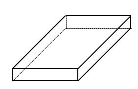
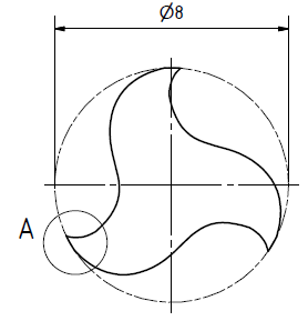
Fig. 4: Sample set (left: flat sample; right: three-edge geometry, A = 5 µm; 10 µm; 15 µm)
| Method | Device | Object of characterization |
| Calotte grinding | KSG110 | Determination of the coating thickness, calculation of the coating rate |
| Scanning electron microscopy (SEM) | JEOL 6610 | Imaging of the surface morphology, coating structure |
| Energy dispersive X-ray spectroscopy (EDX) | JEOL 6610 + XMax 80 mm2 | Determination of the chemical composition |
| X-ray diffraction (XRD) | BRUKER 5500 | Determination of the crystal structure |
| Focused Ion Beam (FiB), Cross Section Polisher (CSP), Metallogr. preparation | JIB-4610F | Preparation of a layer cross section |
| Optical 3D microscopy | Alicona Infinite Focus | Measurement of edge geometry (edge radius and wedge angle) |
| Instrumented hardness testing | ZwickRoell ZHN 1 | Determination of indentation hardness and indentation E-modulus |
Tab. 4: Analysis methods and devices used
3 Results and discussion
3.1 Chemical and structural analysis
 Fig. 5: Al:Cr ratio as a function of the bias voltageTheAl:Cr ratio is of particular interest when examining the deposited layers (here on flat substrates). This ratio is a function of the process parameters and allows the crystalline phases in the layer to be varied by changing the ratio. Below is the plot(Fig. 5) of the Al:Cr ratio versus the applied negative bias voltage of various coating and deposition variants.
3.2 Coating rate on flat substrates
 Fig. 6: Diffractogram of the AlCrSiN/TiN coating system 66:29:5, N2 pressure 5 PaThecoating or deposition rate ischaracteristicof every coating process. This value indicates the coating thickness that can be achieved in a certain unit of time under the respective process conditions. Depending on the bias voltage applied to the substrate, conclusions can be drawn about the coatability of complex geometries, as higher field strengths act particularly at tips, corners and edges due to effects in the electric field(Fig. 1). The situation is similar in concave areas, depressions, holes, etc., except that the effective bias voltage is lower than the actual bias voltage.
 Fig. 7: Course of the coating rate of various coating systems as a function of the negative bias voltage applied to the substrate. Inconventional monolayer coating systems, such as CrN, there is a linear decrease in the coating rate with increasing bias voltage. Above a threshold voltage, no more coating is applied; instead, the substrate is removed due to the coating particles impacting with high energy. The situation is different with the binary AlCrN system. Here, the coating rate hardly decreases even with increasing voltage from around -300 V. This means that a coating can still be applied even at higher voltages. This becomes particularly clear with nanolayer coating systems such as AlCrSiN/TiN. Here, the simultaneous operation of the two evaporators results in a layered coating structure, which has higher deposition rates and less sinking compared to monolayer systems. The change in the deposition rate indicates the occurrence of the hexagonal AlN phase from a bias voltage above 500 V(Fig. 6 and Fig. 7).
 Fig. 8: Comparison of the state of the art with the new coating system; left: strong edge rounding at 0 V bias; center: Spalling at the edge already at -300 V bias; right: newly developed coating system with formation of a sharp edge at -900 V