As part of a research project, TU Wien has developed a manufacturing process for carbon fiber-reinforced nickel using electroforming. By using embroidered fiber preforms, geometrically complex components can be manufactured close to the final contour. The properties of these composite materials are particularly interesting for applications in the aerospace industry.
Metal matrix composites
Metal matrix composites (MMC) are an innovative class of materials that offer a wide range of improved mechanical, thermal and wear properties. Due to the high requirements in high-tech industries, especially in the aerospace industry, they are interesting materials in this sector. Continuous fiber-reinforced MMCs in particular have the most promising properties, as they can achieve significantly higher strengths than monolithic materials. However, due to the directional dependency, this is only limited to the fiber direction, similar to polymer composites. Most manufacturing processes for fiber-reinforced MMCs are also limited to simple geometric shapes and plastic deformation is no longer possible after production. Added to this is the problem that most classic manufacturing processes require high pressures and temperatures to process the metallic matrix. All of this means that the properties of the fiber reinforcement cannot be optimally utilized.
"Tailored fiber placement (TFP)
These problems are to be circumvented by a new manufacturing process developed at TU Wien (Institute of Chemical Technologies and Analytics, Inorganic Materials Research Group), which takes place at room temperature. This process aims to combine the advantages of "tailored fiber placement" (TFP) with electroforming. The TFP process is a textile manufacturing process for the production of fiber preforms for fiber composites. The fibers to be processed are stitched onto a base material in continuous fiber strands according to a predefined pattern. For the application described here, carbon fiber rovings were used (roving: bundle, strand or multifilament yarn made of filaments arranged in parallel). In principle, glass fibers as well as ceramic and metallic fibers can also be processed in the TFP process. The layer structure and fiber direction can be adjusted using a controllable XY table and a pivoting guide element. The fibers are processed dry (in contrast to Fig. 1: Fiber preform made of carbon fiber on glass fiber base material from the TFP process (Photos: TU Vienna) pre-impregnated fibers such as prepregs), the matrix is applied in a separate work step to obtain the finished component. The advantages of the TFP process include its ability to produce customized components that are tailored to the requirements of the respective area of application. As a near-net-shape manufacturing process, material can be saved and the amount of post-processing required can be reduced. The precise placement of the fibers also enables optimal alignment to be achieved depending on the load path, which allows maximum use to be made of the anisotropic fiber properties. The fiber preforms for the tests (see Fig. 1) were manufactured by the project partner Riedmann Advanced Composites (RAC) from Lustenau, Austria.
Nickel deposition on the carbon fibers
The electrochemical nickel deposition on the fiber preforms was carried out in a nickel sulfamate electrolyte. The electrolyte contains 375 g/L nickel sulphamate, 10 g/L nickel chloride, 40 g/L boric acid and about 100 mg/L sodium lauryl sulphate (SDS) as a wetting agent. No additives were used for the deposition in order not to increase the complexity of the subsequent test series.
The shaping of the components is ensured by specially manufactured sample holders (Fig. 2), which fix the preforms in the desired position. The components of the sample holder are produced using a commercially available 3D printer (filament extrusion) from glycol-modified polyethylene terephthalate (PETG). This allows a high degree of flexibility and fast iteration steps for necessary adjustments. In addition to shaping, the sample holder has numerous other functions, including
-the electrical contacting of the fibers
-placement of anodes for uniform deposition
-a hose connection to convey electrolyte through the fiber bundles
fixing the entire assembly in the electrolyte basin. Fig. 2: CAD drawing of the sample holder for fixing the fiber preforms
In order to achieve the most uniform deposition possible on the fibre preforms, a number of tests were carried out to optimize the process. The best results were achieved by selecting a low current density. It was very important for the tests to ensure sufficient bath movement. This applies in particular to the inter-fiber spaces within the rovings, where the depletion of the electrolyte during metal deposition must be prevented. To this end, the sample holder underwent numerous iteration steps to convey fresh electrolyte through the fiber bundles. In addition, the bath movement was supported by ultrasound application. This is intended to force additional movement in the microscopic spaces between the carbon fibers.
A look inside the composite material
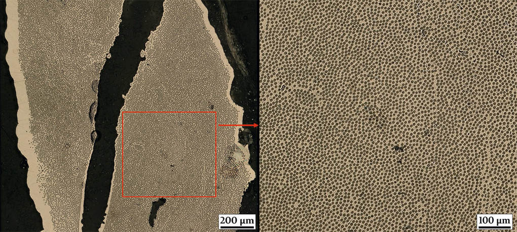
Complete and uniform penetration of the carbon fibers with the metallic matrix is crucial for successful production. The assessment was carried out by analyzing the samples under an optical microscope, as shown in Figure 3. For this purpose, several sample pieces were cut out of the manufactured material after each test using a cutting machine. These sample pieces were embedded in synthetic resin and prepared metallographically. This is done on a grinding and polishing machine with SiC abrasive paper. This is the only way to take high-quality images that allow a look inside the material. The cross-section of the round carbon fibers can be clearly distinguished from the bright nickel matrix. Pores and uncoated carbon fibres can also be easily identified; these features should be minimized by optimizing the deposition process. By evaluating the images, fiber volume fractions of over 40 % could be determined for the best test samples, with a pore volume fraction of only 4 %. These results are comparable to the volume fractions of polymer composites. Fig. 3: Metal matrix composite (MMC) made of carbon fibers with electrodeposited nickel, image taken under an optical microscope
Production of structural components for space travel
Finally, the advantages of the manufacturing process were to be demonstrated using a practical application example. The project partner Beyond Gravity from Zurich, Switzerland, is a company that has been a major player in the Austrian space industry for decades. In addition to satellite components and electronics, the company's core competencies also include thermal systems and structural elements. A specific structural component in use was selected for demonstration purposes. This is to be reproduced using the developed manufacturing process with fiber reinforcement.
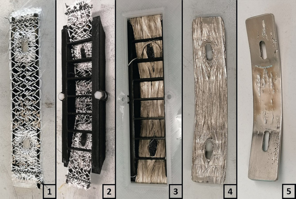
 Fig. 4: Work steps for manufacturing the structural component - original designInthe first step, the component was reproduced true to form (Fig. 4). For this purpose, a fiber preform with the correct dimensions and already integrated slotted holes was designed (1). The flexible fiber preform was integrated into the sample holder, which fixes the fibers in the desired shape (2). Finally, the carbon fibers were pretreated in an acetone bath and placed in the nickel sulfamate electrolyte. The first deposition step (approx. 12-15 h) was then carried out (3). The near-net-shape and dimensionally stable blank (4) could now be removed from the sample holder. In order to obtain flat surfaces and the final component shape, post-processing steps consisting of further nickel deposition and material removal by milling followed (5).
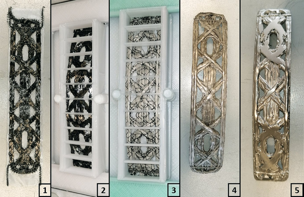
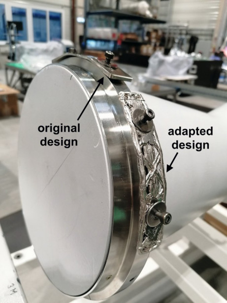
Finally, possibilities were sought to use the design freedom gained through the manufacturing process to optimize the design of the structural component. On the one hand, this concerned the two bends in the original design, which were created exclusively due to the classic manufacturing route. However, as the fixture on which the structural component is mounted is rotationally symmetrical, there can only be point contact between the component and the fixture. A continuous curvature with a larger bending radius would be better for the application, which would enable a planar contact and thus an improved form fit between the components. Furthermore, mass is to be saved by implementing a grid structure instead of solid material. The picture on page 823 shows the original versus the adapted design.
 Fig. 5: Work steps for manufacturing the structural component - adapted design
For implementation (Fig. 5), a new fiber preform was produced with the adapted design elements (1). Furthermore, the sample holder was adapted, which fixes the flexible preform in the adapted geometric shape. After pretreatment of the carbon fibers, nickel deposition was carried out in the nickel sulfamate electrolyte (3). The dimensionally stable blank (4) was then removed from the sample holder. The post-processing steps for this variant were limited to the necessary areas due to the more complex geometry. This included milling out the slotted holes and reworking the surfaces around the slotted holes, which serve as support points for the washers during screw fastening.
 Fig. 6: Test installation of both component variants on a mock-up
Finally, a test installation was carried out at Beyond Gravity. Both component variants were installed on a mock-up to simulate the real installation situation (Fig. 6). Ultimately, this application example demonstrated that the advantages of the TFP process can be utilized. By adapting the fiber preforms and the sample holders for fixing the flexible embroidery, a high degree of geometric design freedom can be achieved. Adjustments to the component can be tested iteratively and implemented quickly.


