
Gear wheels are used in all areas of technology and only work smoothly if they are optimally deburred or chamfered. Studies show that the formation of burrs depends on how the gears are manufactured and that the structure of the material is usually deformed in the vicinity of the burrs and must therefore be removed by chamfering. Large burrs are created, for example, when the cutter exits the workpiece, but a so-called Poisson burr is also created at the start of the hobbing process. The process, which can also chamfer such burrs in places that are geometrically difficult to access, uses milling cutters that can produce high-quality chamfers of up to 2 mm in size in a very short time after synchronizing the rotation angles of the tool and workpiece. The precision of the chamfers is verified by means of a contour measurement and by analyzing the chips produced.
 Fig. 1: Gear produced by hobbing with pronounced burr formation on the exit side of the hobThetypical symbol of mechanical engineering for hundreds of years has been the gear wheel, which moves machines or vehicles and generally ensures that rotary movements can be transmitted and/or translated. Gears are manufactured by casting, forging, fine blanking or with machining processes such as hobbing, gear shaping, gear skiving or broaching. Machining processes are mainly used for gears when large forces need to be transmitted and/or when the gears need to run smoothly and particularly quietly even at high speeds. All cutting processes produce more or less large burrs when the gear cutting tool exits the tooth space onto the flat surfaces of the gears (Fig. 1).
Not all burrs are as pronounced as in Figure 1, but even smaller burrs or sharp edges can make a gear unusable for its intended use. When such gears are further processed and mounted for use in a gearbox, the following problems can occur:
- Further handling can injure the personnel involved
- The gear can be damaged at the tooth face edges during transportation
- Over-carburization of the edges during heat treatment by case hardening can cause edge chipping during subsequent use
- The flat surfaces of the gears are often used as a stop surface or as a clamping surface for subsequent hard finishing; only burr-free flat surfaces can guarantee trouble-free further processing
- The service life of tools for subsequent hard finishing, such as grinding wheels or honing tools, is impaired
- Problems can occur during the assembly of gearboxes, especially if this is done automatically
- Damaged flanks or residual burrs on the gears result in increased noise emissions from the gearboxes
- Burr residues can destroy a gearbox due to their abrasive effect
For these reasons, all machined gears are deburred. Most mechanical deburring processes leave sharp edges, which are increasingly unsatisfactory due to the increasing demands placed on gears and gearboxes.
If the required deburring quality of gears is not exceptionally high, one of the simpler processes can be used. In addition to non-targeted processes such as vibratory grinding, electrochemical bath deburring or thermal deburring (TEM), there is also the method using deburring wheels or filing wheels. They are all able to safely remove burrs from the gear cutting process, but leave behind sharp edges, sometimes with residual burrs (Fig. 2).
 Fig. 2: Image of a gear machined with a deburring wheel. In addition to the "cut" surface, the residual burrs on the tooth face edges are clearly visible
![Abb. 3: Gratentstehung beim Austritt eines Fräsers unter verschiedenen Winkeln [1]](/images/stories/Abo-2020-09/image4_korr.jpg "Abb. 3: Gratentstehung beim Austritt eines Fräsers unter verschiedenen Winkeln [1]") Fig. 3: Burr formation at the exit of a cutter at different angles [1]
Fig. 3: Burr formation at the exit of a cutter at different angles [1]
To produce a gear with good deburring quality, without residual burrs and sharp edges, the best method is to apply a defined chamfer. This ensures that no residual burrs impair the flat surfaces of the gears and enables, for example, assembly in a gearbox without any damage to the mating gear due to a sharp and hardened tooth face edge.
This can be confirmed by analyzing the resulting burrs, which also shows why and to what extent such burrs must occur in the aforementioned gear cutting processes and cannot be avoided.
Macroscopic burr detection
 Fig. 4: Burrs detached from the gear as in Fig. 1; magnification approx. 50xThedescription of the burr geometry is based on the spur gearing from Fig. 1, as this is particularly illustrative. The burr formation was examined in metallurgical grinding, among other things, and can therefore be quantified. From the micrographs, conclusions can be drawn about the change in the material in the edge zone during burr formation.
The burr is first detected macroscopically. Figure 1 shows that a very large burr is pressed out both on the tooth flanks and in the base between the teeth when the milling cutter exits, partly because the rake angle of the milling cutter must be 0° due to the tooth geometry. The burrs near the base of the tooth are a burr in the interdental space and at the base of the adjacent teeth at the top, a burr almost exclusively in the interdental space below (red arrow) and a burr mainly to the right and left of the interdental space at the bottom. This irregularity is typical for this type of cutting and is related to the current angle at the time the milling cutter emerges into the flat surface. This makes deburring more difficult with conventional systems, but not with the system of the machine in this project.
The nature of the resulting burrs is in line with the literature, in which a very large burr was identified at the cutter exit below 90° (Fig. 3). The burrs themselves are several millimeters in size and usually roll up due to the compression during machining (Fig. 4).
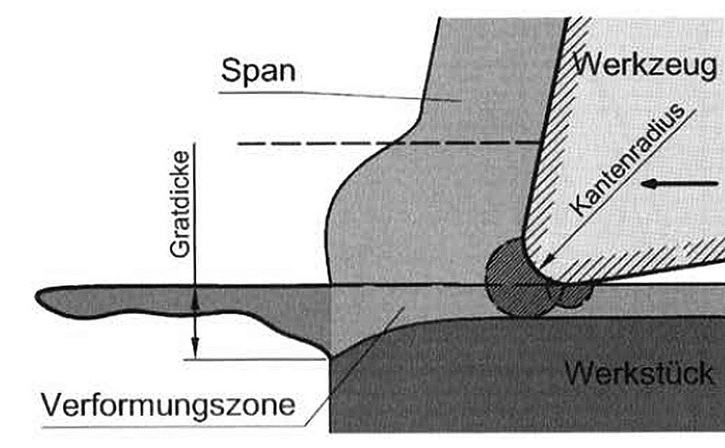

Fig. 5: Deformation zones at the milling cutter exit (left: schematic, right: microsection)
In the literature, burr formation during machining processes is described as the material to be machined yielding to the cutting force. At the edge of the workpiece, the compressed material "folds" over the edge and thus creates the burr (Fig. 5). This burr formation can be demonstrated microscopically on the existing test samples (Fig. 6 and 7).
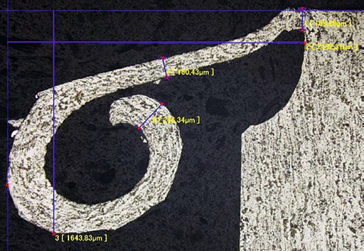

Fig. 6 and 7: Deformed burr from hobbing (cross section from the gear wheel in Fig. 1)
The change in the microstructure only becomes clear at higher magnification (Figs. 8 and 9). Here it can be seen that the microstructure of the material is damaged by the milling cutter to a depth of several µm, which continues into the burr and whose completely compressed microstructure no longer matches that of the base material. This is one of the reasons for generously chamfering the tooth edges, namely to remove the damaged microstructure.
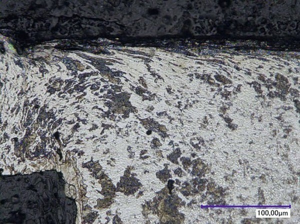
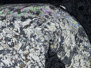
Fig. 8 and 9: Burr root structure, sections from Fig. 6 and 7, 1000-fold
In addition to the burrs described above, the formation of burrs on the tool entry side is also described in the literature. This is also due to the deflection of the material when the cutting force is applied. In the test samples, burrs can be detected both on the tool entry side and on the tip circle diameter or tip taper. The extent of these burrs, referred to in the literature [3] as "Poisson rates", is significantly lower than at the exit point of the tool.
How Poisson's ridges are formed
Figure 10 shows the burrs on the end face on the tool entry side. A particularly pronounced burr formation was observed in the area of the transition from the tooth flank to the root circle.
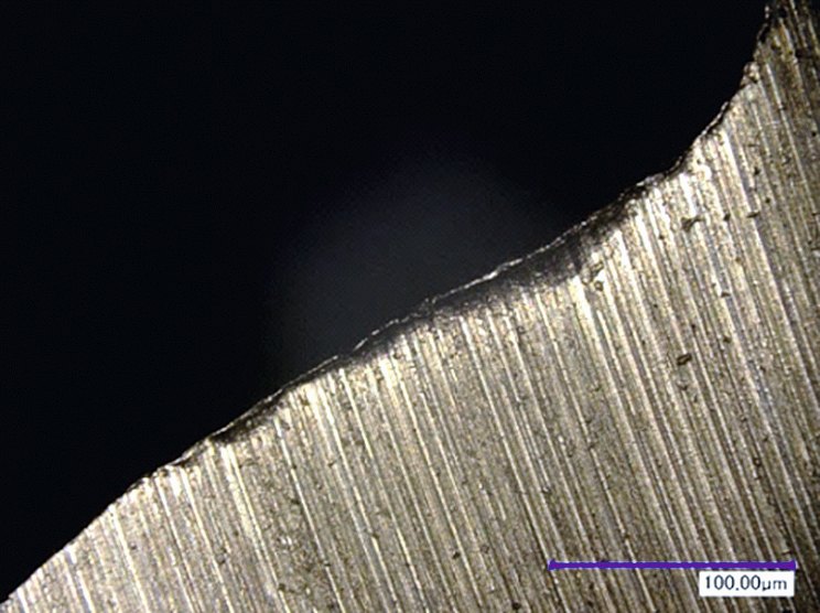
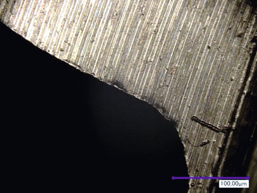
Fig. 10: Burr on the tool entry side - so-called Poisson burr, 100-fold
In addition to the face surfaces, the tip surfaces on the gear can also be affected by the formation of Poisson burrs (according to [3]). Figure 11 shows such a burr on the tip cone of a bevel pinion.
Figure 12 can be used to estimate the size of these burrs. Burrs of up to approx. 90 µm can occur on the face and tip surface.
 Fig. 11: Poisson burr on the head cone, 100x
 Fig. 12: Poisson's ridge on the end face, section from Fig. 10, 500x
Poisson's ridges can therefore have a detrimental effect on subsequent processes, particularly because they are not so obvious due to their small size. This is another reason why it makes sense to chamfer both sides of the workpiece.
New process for better results
 Fig. 13: Gear wheel that is difficult to chamfer; a burr from the gear shaping or gear skiving process forms especially in the narrow space between the two respective gear teeth; this can be removed using the radial gear chamfering processIn addition tothe existing processes on the market that can chamfer gear wheels as required and described, a method that can produce chamfers quickly and precisely on the tooth face edges, especially on components with interfering contours, has been lacking until now. Particularly due to the current emergence of electromobility, gearboxes and therefore gears are becoming smaller and more complex for reasons of lightweight construction and energy efficiency, but also for combustion engines. This in turn means that more and more workpieces with interfering contours are being produced (see Fig. 13 for an example), which are very difficult or impossible to deburr automatically.
These workpieces have to be deburred manually, with the corresponding fluctuations in quality and cycle time of a monotonous, tedious task at comparatively high costs.
With the newly developed Radial Gear Chamfering process, the above requirements can be met in equal measure. A radially positioned end mill with a geometry calculated on the basis of the tooth geometry and the required chamfer design is used. The RGC 350 chamfering machine developed for this technology ensures that the speed of the cutter and its position are precisely synchronized with the teeth of the gear.
After synchronization, the gear is precisely chamfered within a few seconds. This can be achieved with tooth shapes that are easy to machine, as in the example in Figure 1, as well as with helical spur gears or spiral bevel gears, for example.
The advantages of the radial gear chamfering process are not only the short machining time and the good quality of the chamfer, but also the great flexibility, especially for workpieces with interfering contours, which makes this process interesting. The resulting costs per workpiece make the radial gear chamfering process not only technically but also economically attractive due to the short cycle times.
After synchronizing the rotation angles of the gear and milling cutter, the rotation angle of the milling cutter is determined at the start of machining. At the same time, the cutter geometry is calculated so that cutters can be manufactured from suitable cutting materials, adapted to the respective gears and machined. During initial machining, it was possible to chamfer and deburr the gearing despite very strong burrs on the tooth face edges. The desired chamfer depth was 0.5 mm (selectable between 0.2 and 2 mm); alternatively, the chamfer width could also be specified. In order to be able to precisely determine the actual chamfer depth produced in this case, the contour of the chamfer was recorded and visualized using a contour measuring device (Hommel-Etamic, type T8000 RC). Figure 14 shows an excerpt from the measurement report, which shows a section in the area of the tooth height center. The angular deviation of the two chamfers is less than 3°. This error was significantly reduced during further optimization.
 Fig. 14: Measurement report of the chamfer with a target depth of 0.5 mm
 Fig. 15: Result with the current generation milling cutter
Reducing secondary burrs
The milling cutters have since been further developed several times and in the current generation the tool geometry has been optimized so that the milling cutters can be manufactured from carbide. The previously introduced positive rake angle has proven its worth on all components, machining has been optimized and the formation of secondary burrs has been significantly reduced. The chamfers now obtained have an almost ideal shape and there are no longer any significant secondary burrs in the tooth flank. The surface is significantly smoother, as can be seen from the gloss in the chamfer in Figure 15. However, there is a slight asymmetry on the components, which can easily be avoided if the machine settings are improved.

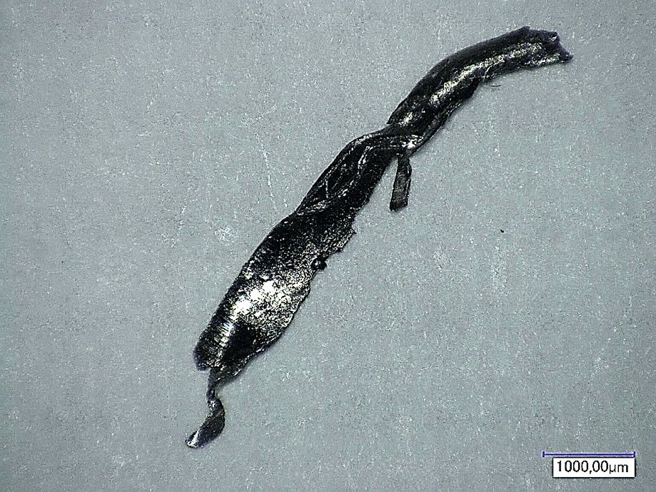
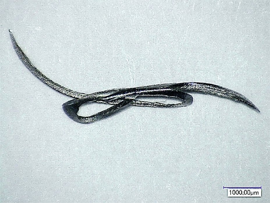
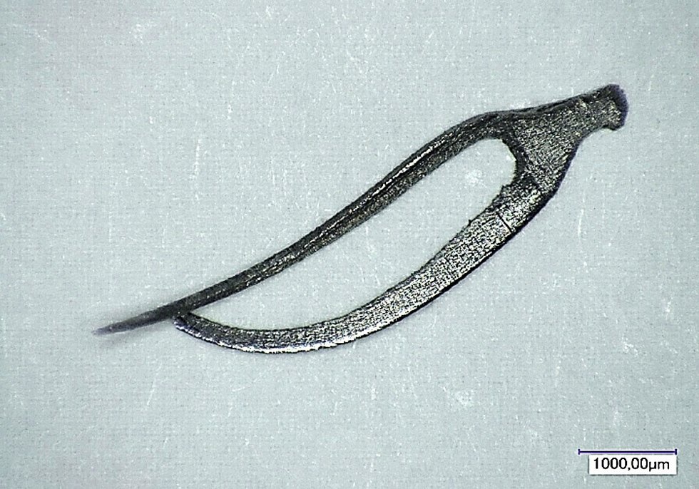
Fig. 16: Chips from the final test series with a milling cutter of the current generation
![Abb. 17: Der Wärmefluss bzw. die Temperaturströme bei der Zerspanung von Stahl (nach [4, 5])](/images/stories/Abo-2020-09/2301.png "Abb. 17: Der Wärmefluss bzw. die Temperaturströme bei der Zerspanung von Stahl (nach [4, 5])") Fig. 17: The heat flow or temperature currents during the machining of steel (according to [4, 5])Despite a cutting speed of vc = 170 m/min and dry machining, the chips show no signs of thermal stress on the tool or even damage (Fig. 16). In such a case, the chips would be discolored with tarnish. Since approx. 75 % of the energy supplied to the process flows into the chip (Fig. 17), the overall heat development during the process at small fiber depths can be classified as very low.
Fig. 17: The heat flow or temperature currents during the machining of steel (according to [4, 5])Despite a cutting speed of vc = 170 m/min and dry machining, the chips show no signs of thermal stress on the tool or even damage (Fig. 16). In such a case, the chips would be discolored with tarnish. Since approx. 75 % of the energy supplied to the process flows into the chip (Fig. 17), the overall heat development during the process at small fiber depths can be classified as very low.
The chips have a uniform and even cutting surface, which indicates a peeling and therefore harmonious cutting process. In Figure 16, the tooth gap shape of the component is partially visible on the chip, which indicates a continuous passage of the tool cutting edge through the tooth gap, as planned. At no point does the cutting force break off due to vibrations or other damaging influences.
The working area of the RGC 350 deburring machine is clearly laid out and open (Fig. 18). This ensures free chip fall during dry cutting and also prevents collisions in the work area. All guides, cables and moving parts are well protected behind the covers from the needle chips produced during the process. The RGC 350 can be used flexibly as a stand-alone machine; however, the machine can also be easily linked to gear hobbing or gear shaping machines and integrated into a production line using an appropriate automation solution. With a footprint of around 2 m², this machine can be set up quickly and easily in production. The short cycle times can be realized with the powerful workpiece and tool spindles. Gear wheels with a diameter of up to 350 mm or gear shafts with a length of up to 350 mm can be machined. The standard workpiece holders available on the market can be used, special clamping devices are not required (Fig. 19). Setting up the machine is quick and easy, and knowledge of CNC programming is not required thanks to the intuitive graphical user interface (Fig. 20). Only the set-up data provided with the tool needs to be entered into the corresponding masks. There is also no need to measure the tools, as all data is provided with the tools.
 Fig. 18: RGC 350 machine for chamfering gears. The operating unit on the right-hand side of the picture
 Fig. 19: Setting up the machine with a suitable clamping device for a new gear wheel
The RGC 350 machine with the radial gear chamfering process works very economically for small and medium-sized series. However, it is also a real cost-effective alternative to existing processes for large quantities. The application is particularly interesting for gears or gear shafts in situations that are very difficult to machine, e.g. with closely spaced gears (e.g. workpieces as shown in Fig. 21) or with interfering contours.
 Fig. 20: User interface of the RGC 350 machine
 Fig. 21: RGC 350 chamfering machine deburring a two-stage sprocket
