
Deburring bores that intersect and cross inside workpieces is difficult. In a study, workpieces made of free-cutting or heat-treated steel and a high-strength aluminum alloy, all of which had extremely complicated deburring situations, were deburred using different methods and compared. In this first of two parts, the performance of some common methods is examined.
In metalworking, deburring is an operation that is required as a result of many processes. For example, cast parts cannot be used without fettling, deep-drawn parts usually require an edge to be cut off and bores are usually followed by countersinking. If the burrs are easily accessible on the outside of the workpieces, deburring is usually not a technical difficulty and only needs to be planned using one of the many known processes. This is much more complicated for bores that intersect inside the workpieces - and all the more so the smaller the series, so that an expensive process is not worthwhile and especially if the variants of the bore intersections are manifold. Such a situation, in which both obstacles occurred, was the reason for the present study, in which the technical suitability of the possible processes was examined and their economic efficiency calculated.
The reasons for deburring (Fig. 1) were formulated many years ago [1] and nothing has changed to this day, except that some machining processes have become more precise and in some cases the burrs are smaller as a result. As a result, it may be sufficient for many workpieces either not to deburr them at all or to treat them with a much simpler process than would have been the case in the past.
Starting point of the investigation and burrs that occur
The range of parts involves workpieces made of free-cutting or heat-treated steel and a high-strength aluminum alloy, which are assembled into a ready-for-sale assembly in a separate assembly department after finishing. As manual deburring on the machine impairs the machine running time and ancillary work such as pinning individual parts cannot be dispensed with in assembly, i.e. work that generates chips is required anyway, the deburring of complex contours has so far been transferred almost entirely to assembly. Around 20 to 40 % of the working time in mechanical engineering assembly is spent on deburring [2]. In another study [3], deburring accounts for 20 to 30 % of production costs or 30 % of the production time for the corresponding workpieces. In a comparison of the situation on which this is based, the result is roughly the same even decades later.
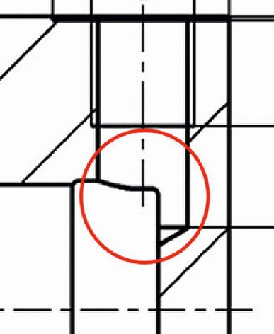
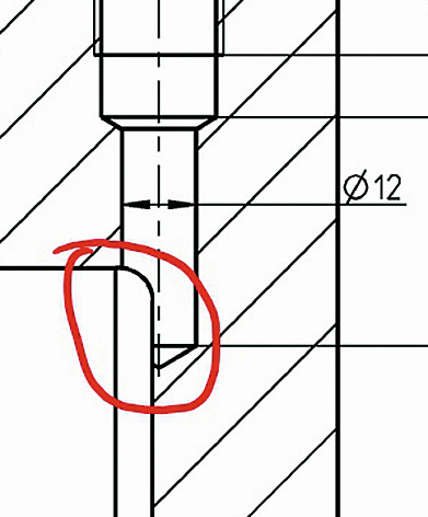
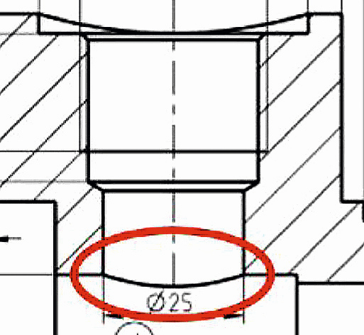
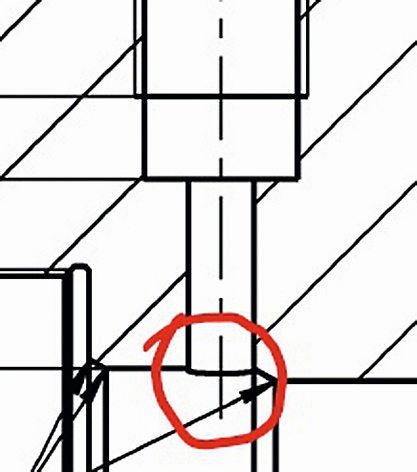
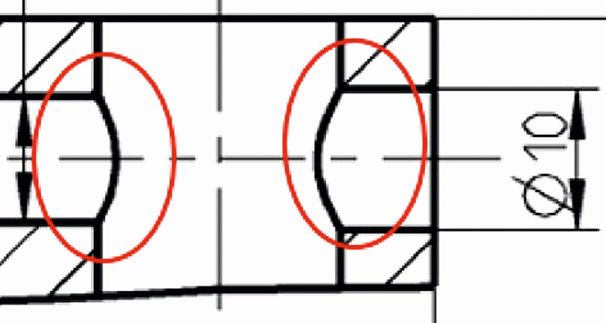
Fig. 2 to 6 (from left to right): Partial drill exit of a small bore into a larger bore; complete drill exit of a small bore into a large bore; intersecting bores with the same or different diameters
In the following pictures, some typical burrs from the inside of various workpieces are shown partly as sections from drawings (Fig. 2 to 6) and partly as photos (Fig. 7 to 15). Both the drawing sections and the photos show extremely complicated deburring situations, which have so far been processed manually with more or less good, but mostly fluctuating deburring quality. It is obvious that some of the details could probably be alleviated by a better design, but in many cases this is made more difficult or prevented by the required compactness of the parts.
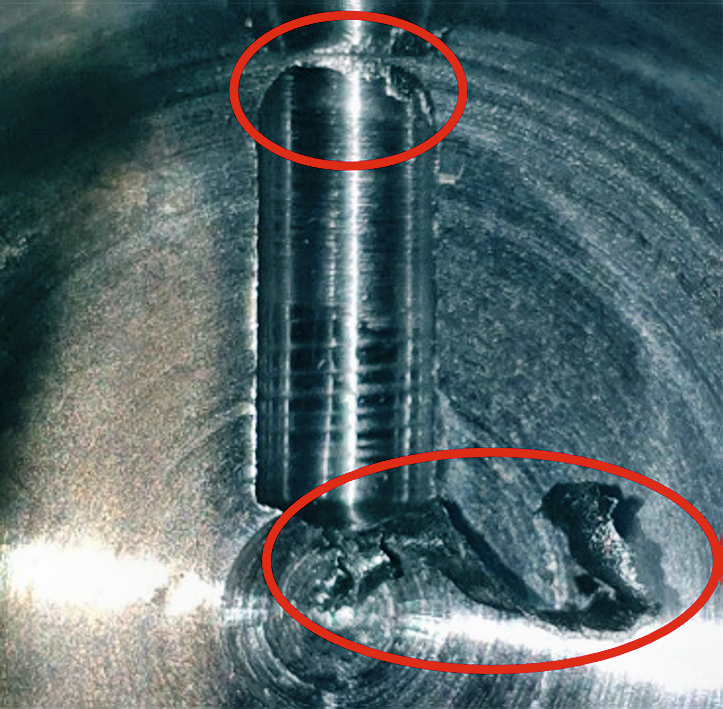
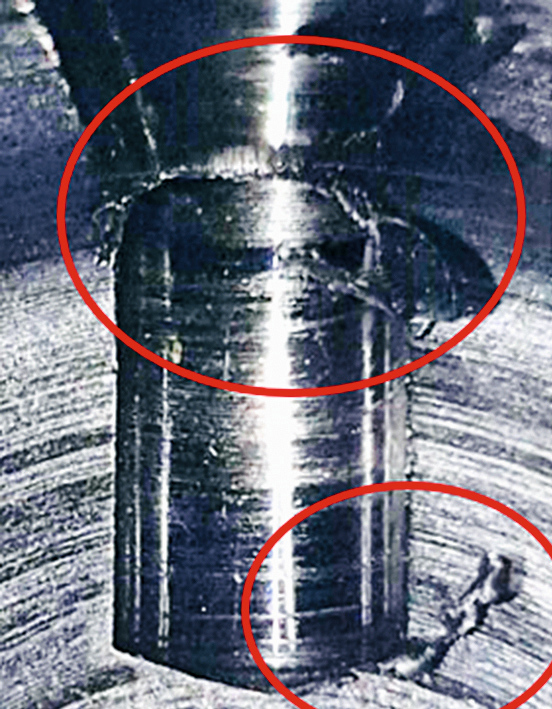
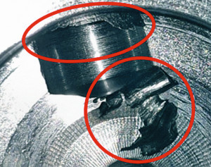
Fig. 7 to 9 (from left to right): Emergence of a "half" hole into the end wall of a larger hole
In particular, the holes in Figures 2 and 3 as well as 7 to 9 are very unfavorable for production because the drill only partially works in the material shortly before reaching the correct depth. However, due to the function of the holes, a more favorable design is not intended for these parts. For this reason, these workpieces have burrs both at the exit of the hole from the solid material and at the end of the hole, each of which must be deburred separately.
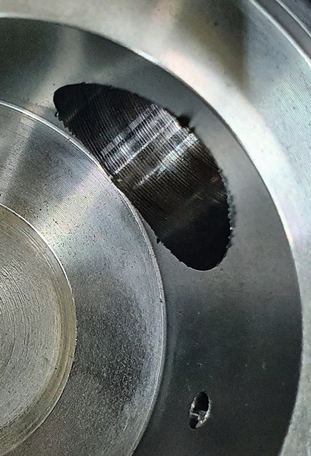
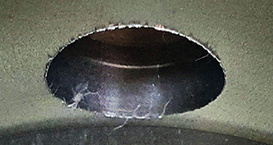
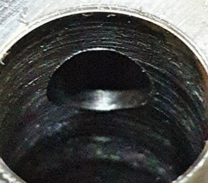
Fig. 10 to 12 (from left to right): Emergence of smaller bores into a larger bore in each case
In the burrs shown in Figures 4 and 5 and photos 10 to 13, the entire diameter of the smaller drill bit passes through the inner wall of the larger hole, resulting in a relatively low annular burr with a height of between 0.1 and 0.5 mm. It is to be expected that these burrs are much easier to machine. Finally, a third type of burr occurs when bores cross, i.e. intersect at an angle of 90° as shown in Figures 6, 14 and 15, whereby smaller burrs tend to form. It should therefore be noted that burrs occur for which a suitable process should definitely be found and those that are more likely to be considered "free-form" and for which manual deburring will most probably have to be retained. The number of parts to be deburred per year is in the order of 80,000, whereby the many different variants mean that batch sizes are only a maximum of a few hundred parts.

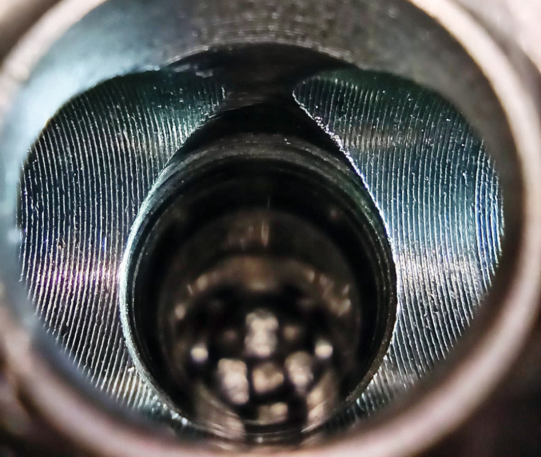
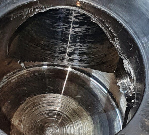
Fig. 13 to 15 (from left to right): Emergence of 2 bores into one larger bore each; intersecting bores and meeting of several bores of different sizes
Selection of deburring processes
According to [4], there are over 120 deburring processes available for workpieces made of metallic materials, which could in principle be suitable for the workpieces in question. However, processes that would damage adjacent surfaces that have already been machined or those that cannot reach the burrs due to geometric conditions must be completely ruled out. Following a discussion with experts, a preliminary selection of processes was made, which were to be tested for their suitability both theoretically and in trials. Another criterion for the selection was the required deburring quality. Some points come into contact with other parts when the assemblies are in use and require complete deburring, preferably with a small chamfer or a small radius, while in other positions the burrs only need to be removed to the extent that no more material particles can become detached. Finally, the machining time for deburring and the costs must be taken into account when selecting the process. The processing time must not interfere with subsequent processing or assembly and intermediate storage or complicated parts logistics must be avoided.
![Abb. 16: Werkzeuge COFA, DEFA, DL2, SNAP, GH-K [5]](/images/stories/Abo-2022-09/gt-2022-09-0064.jpg "Abb. 16: Werkzeuge COFA, DEFA, DL2, SNAP, GH-K [5]") Fig. 16: Tools COFA, DEFA, DL2, SNAP, GH-K [5]
Fig. 16: Tools COFA, DEFA, DL2, SNAP, GH-K [5]
In addition to manual deburring, the following processes were therefore shortlisted:
- Automated deburring in the machining center
- Robot-assisted deburring in a deburring cell
- thermal-chemical deburring (TEM)
- electrochemical deburring (ECM) and
- high-pressure water jet deburring.

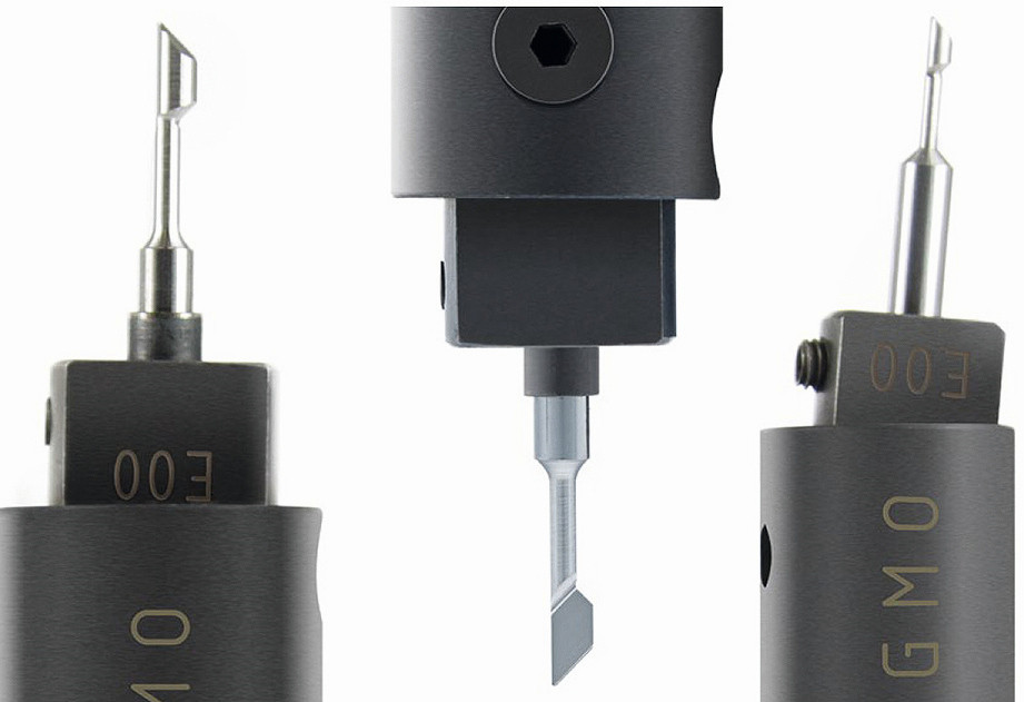
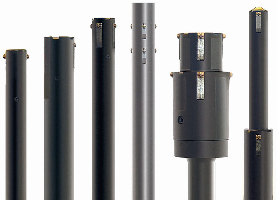 Fig. 17: Tools from the Back Burr Cutter, GMO, HSD programs, various special deburring tools such as Burr-Off or Burraway as well as mounted points and ceramic fibre brushes [6]
Deburring in the machining center and with the industrial robot
![Abb. 18: Schematische Darstellung der Funktion einer TEM-Anlage [9]; dabei bedeuten 1: Entgratkammer, 2: Maschinengestell, 3: hydraulisches Schließsystem, 4: Rundtischantrieb, 5: Schließteller, 6: Rundschalttisch, 7: Absaugung, 8: Mischblock, 9: Zündeinrichtung, 10: Gasventile, 11: Hydraulik, 12: Gasdosiersystem (bei neueren Anlagen durch Proportionalventiltechnik ersetzt), 13: Schallschutzkabine](/images/stories/Abo-2022-09/gt-2022-09-0070.jpg "Abb. 18: Schematische Darstellung der Funktion einer TEM-Anlage [9]; dabei bedeuten 1: Entgratkammer, 2: Maschinengestell, 3: hydraulisches Schließsystem, 4: Rundtischantrieb, 5: Schließteller, 6: Rundschalttisch, 7: Absaugung, 8: Mischblock, 9: Zündeinrichtung, 10: Gasventile, 11: Hydraulik, 12: Gasdosiersystem (bei neueren Anlagen durch Proportionalventiltechnik ersetzt), 13: Schallschutzkabine") Fig. 18: Schematic representation of the function of a TEM system [9]; where 1: deburring chamber, 2: machine frame, 3: hydraulic clamping system, 4: rotary table drive, 5: clamping plate, 6: rotary indexing table, 7: extraction system, 8: mixing block, 9: ignition device, 10: gas valves, 11: hydraulics, 12: gas dosing system (replaced by proportional valve technology in newer systems), 13: Noise protection cabinInthe machining center or with the robot, processes from the group of machining with geometrically defined cutting edges are preferable, as some of the processes of machining with geometrically undefined cutting edges such as blasting or vibratory grinding either impair the adjacent surfaces or do not reach the burrs. Only grinding tools with a defined shape such as mounted points would be conceivable instead of a milling cutter or countersink. Using such tools in the machining center is preferable because the workpieces are already clamped and in a geometrically defined position. It is therefore only necessary to keep the tools required for deburring in the magazine and to write a program section for the deburring process. The employees are familiar with the use of the corresponding tools, whereas employees would first have to be trained for new processes or new employees would have to be hired. However, it should be noted that a magazine with sufficient free spaces must be available, especially if several tools for different bore diameters are required for deburring several points. On the other hand, deburring extends the dwell or processing time of the workpiece in the machining center and, in contrast to less demanding workstations, a machining center is comparatively expensive. In addition, license costs are incurred for CAM programming. The following machining steps must be planned:
Fig. 18: Schematic representation of the function of a TEM system [9]; where 1: deburring chamber, 2: machine frame, 3: hydraulic clamping system, 4: rotary table drive, 5: clamping plate, 6: rotary indexing table, 7: extraction system, 8: mixing block, 9: ignition device, 10: gas valves, 11: hydraulics, 12: gas dosing system (replaced by proportional valve technology in newer systems), 13: Noise protection cabinInthe machining center or with the robot, processes from the group of machining with geometrically defined cutting edges are preferable, as some of the processes of machining with geometrically undefined cutting edges such as blasting or vibratory grinding either impair the adjacent surfaces or do not reach the burrs. Only grinding tools with a defined shape such as mounted points would be conceivable instead of a milling cutter or countersink. Using such tools in the machining center is preferable because the workpieces are already clamped and in a geometrically defined position. It is therefore only necessary to keep the tools required for deburring in the magazine and to write a program section for the deburring process. The employees are familiar with the use of the corresponding tools, whereas employees would first have to be trained for new processes or new employees would have to be hired. However, it should be noted that a magazine with sufficient free spaces must be available, especially if several tools for different bore diameters are required for deburring several points. On the other hand, deburring extends the dwell or processing time of the workpiece in the machining center and, in contrast to less demanding workstations, a machining center is comparatively expensive. In addition, license costs are incurred for CAM programming. The following machining steps must be planned:
- Select suitable tool holders for the deburring tools
- Measure the tools and enter them in the tool list of the machining center
- Adapt the workshop programming for the workpiece and enter the tool call in the machining cycle
- Insert the deburring tool and deburr
- Check the deburring result.
Nevertheless, deburring in the machining center is preferable to machining with an industrial robot, as this requires a similar amount of programming and transport from the machining center to the robot in addition to a not inconsiderable investment. On the other hand, a robot can be operated in parallel to the machining center and allows faster production per unit of time if deburring does not take longer than the production of the parts in the machining center. One advantage of deburring with a robot is the possibility of running the machining process unmanned at night or at weekends with automated feeding and removal of the workpieces. Which of the two options, tool-guided or workpiece-guided deburring, is used depends on the size of the workpieces, the number of difficult or easy-to-access processing points and other aspects, and could also be combined under certain circumstances.
![Abb. 19: Anlage zum thermisch-chemischen Entgraten iTEM 400/600 [10]](/images/stories/Abo-2022-09/gt-2022-09-0071.jpg "Abb. 19: Anlage zum thermisch-chemischen Entgraten iTEM 400/600 [10]") Fig. 19: System for thermal-chemical deburring iTEM 400/600 [10]
Fig. 19: System for thermal-chemical deburring iTEM 400/600 [10]
A large number of countersinks, reverse countersinks (Fig. 16), milling cutters, deburring knives, brushes or mounted points are available for the type of application described so far (Fig. 17), with which a very large number of deburring problems can already be solved.
Thermal-chemical deburring (TEM)
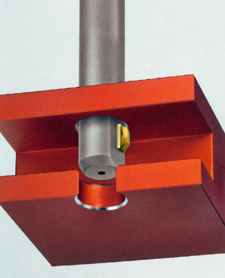
![Abb. 20: Funktionsschema des elektrochemischen Formentgratens [11]](/images/stories/Abo-2022-09/gt-2022-09-0072.jpg "Abb. 20: Funktionsschema des elektrochemischen Formentgratens [11]") Fig. 20: Functional diagram of electrochemical mold deburring [11] According to DIN 8590, thermal-chemical deburring is in the main group 3 "Cutting", group 3.4 "Removal", in subgroup 3.4.2 "Chemical removal" and forms the further subdivision 3.4.2.2 [7]. The abbreviation TEM stands for thermal deburring method. In this process, deburring is carried out with a fuel gas/oxygen mixture that is ignited in a closed chamber. The burrs on the component vaporize, melt or burn, depending on the material, or are already separated by the pressure wave of the chemical reaction.
Fig. 20: Functional diagram of electrochemical mold deburring [11] According to DIN 8590, thermal-chemical deburring is in the main group 3 "Cutting", group 3.4 "Removal", in subgroup 3.4.2 "Chemical removal" and forms the further subdivision 3.4.2.2 [7]. The abbreviation TEM stands for thermal deburring method. In this process, deburring is carried out with a fuel gas/oxygen mixture that is ignited in a closed chamber. The burrs on the component vaporize, melt or burn, depending on the material, or are already separated by the pressure wave of the chemical reaction.
Figure 18 shows how the process works in principle. The workpiece is either clamped loosely in a holding device or placed as bulk material in a basket in a hermetically sealable chamber and the chamber is closed. Methane or hydrogen is used as the fuel gas. The mixture is ignited by an ignition device and burns within 20 milliseconds due to a controlled excess of oxygen. A temperature of 2,500 to 3,300 °C is reached. The burrs on the workpiece have a large surface area compared to their volume, so that they cannot dissipate the heat absorbed by heat radiation into the interior of the workpiece and are immediately vaporized, burned, blown away or fused with the component surface with the help of the additional pressure wave generated. The cycle time is between 30 and 60 seconds [8]. The intensive activation of the surface leaves a black oxide layer on the workpiece, which must be removed by a subsequent cleaning process or by pickling. The workpiece is briefly heated to more than 100 °C and subjected to pressure peaks. These loads are not suitable for all component thicknesses and materials.
Low-carbon steels and high-alloy austenitic steels are very suitable for TEM. The deburring result is poorer for steel alloys with a higher carbon content and low-alloy steel as well as aluminum alloys. This is due to temperature-dependent structural changes in some materials, thermal conductivity and the temperature difference between the metal and the oxide [8]. Burrs with a large burr thickness can only be deburred with limited process reliability, as detachable residual burrs can occur. Thin burrs from machining are more favorable.
If the entire deburring process is considered, parts handling on the deburring system can be automated for higher quantities. However, if there is a large variety of parts, it makes sense for an employee to operate the machine. This person can place the parts in prefabricated devices according to size and type, remove the parts again and sort them accordingly for the rest of the process. As an example, Figure 19 shows a TEM system from ATL Anlagentechnik Luhden GmbH with the designation "iTEM 400/600" [10].
Electrochemical deburring
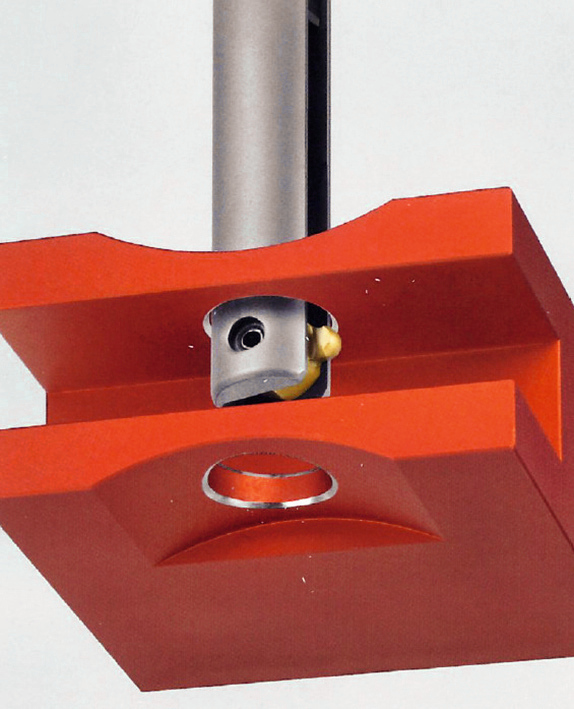
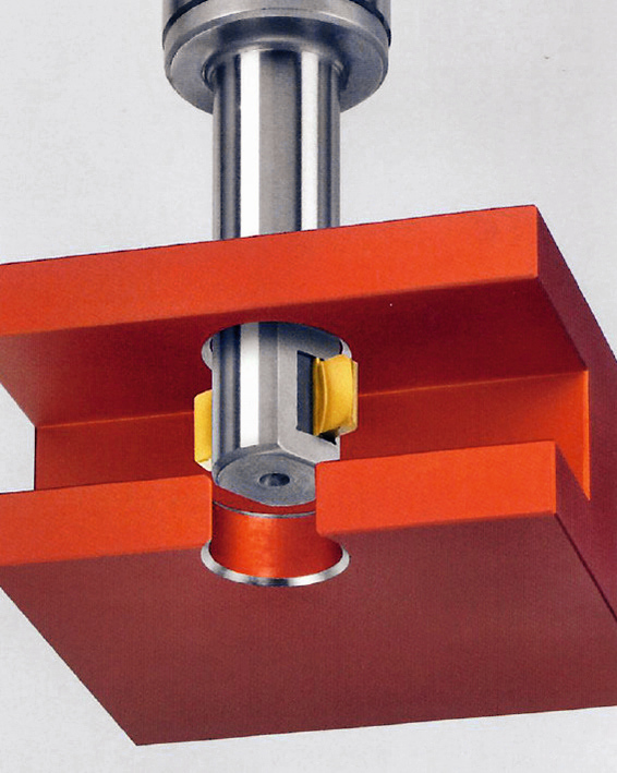
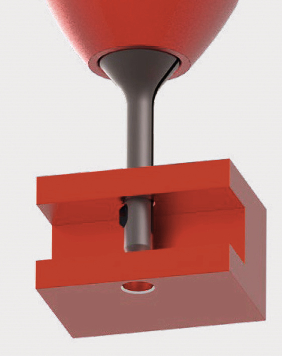
Electrochemical mold deburring, or ECM for Electro Chemical Machining for short, is the most suitable of the various process variants for electrochemical deburring. In this process, an electrochemical reaction between the tool and the workpiece removes the burr without contact. The current density is concentrated at the burr points and the material is preferentially removed at narrow points where the electrolyte flows relatively quickly between the burr and the electrode. The workpiece is connected as the anode and the tool as the cathode. They are surrounded by an aqueous electrolyte in the system, which is supplied under pressure. To activate the reaction, the current flow is generated via an external current source, which causes electron transport in the flowing electrolyte (Fig. 20).
Easily detachable metal atoms with a high concentration of current lines, such as burrs, detach from the workpiece surface and the part is deburred. The resulting waste products in the electrolyte are filtered out and disposed of in accordance with legal regulations [8].
The workpieces must be electrically conductive, grease-free and clean for the process to work and for a current to flow. In addition, there must be no rolling chips, thick burrs or large burrs on the workpiece. If the burr bridges the gap between the tool and the workpiece, a short circuit may occur, causing machine downtime or damage to adjacent components. The cathode must have the negative shape of the contour to be deburred in order to achieve reliable deburring [12]. The burr body should be approximately the same size and should not vary excessively from component to component, as otherwise the deburring results will differ. If targeted removal is to be carried out at the base of the burr, additional insulating materials such as polyurethane are required on the electrode. These protect the rest of the component from material removal. The distance between the cathode and the workpiece also has a significant influence on material removal. If these conditions are taken into account, this process can have an advantage over other processes due to the following points:
- Very low cathode and tool wear
- reliable deburring within 10 to 180 seconds
- No secondary burrs and structural changes
- Very suitable for internal bore intersections
- Edges are rounded, which is favorable in terms of flow for hydraulic components
- Material removal can be adjusted via the current integral current per second [12].
When evaluating the deburring processes, however, the effort and costs for the design and manufacture of the devices must be taken into account. In addition, electrolyte residues must be removed from the workpieces before the parts are further processed. Desalting is usually carried out with water and neutral detergent. Further processing must take place immediately after machining or the workpieces must be protected against corrosion [13].
