
The control of the steam boiler presented in part 6 has many variants. This part of the article series deals with regulators and valves, condensation systems and the electrogalvanic voltage of steam from boilers with heating outputs of 7-30 kW.
Regulators and valves
 Fig. 2: Electrically heated steam boiler, with sealed, calibrated liquifantsIfthe water level in the boilerwerenot reliably monitored, the consequences would be catastrophic. If the water level drops too low and the boiler tubes are outside the water, the boiler tubes overheat to more than 500 °C, which would lead to an explosion of the free hydrogen. In this case, an oxyhydrogen explosion would be the result.
If the water level is too high, the water could run into the steam system and interrupt the steam process. For this reason, the level is regulated with controls. In order to meet legal requirements, control systems and alarm functions are visibly arranged for the operator and automatically initiate the controlled shutdown of the boiler without operation, especially in the event of problems with the water level. A common method of level control is the installation of probes that monitor the water level in the boiler using the "power free method". Power failures or shutdown lead to the emergency stop function of all heaters and drives. All probes have a dual design with parallel control.
If a limit value is reached, a control unit sends a signal to the feed pump, which starts to work to restore the water level in the boiler and switches off when a predetermined minimum level is reached. The probe has fixed, non-adjustable, integral levels at which the pump is switched on and off, activating alarms or shutting down the systems at low or high levels. Alternative systems use floats as signaling devices. With all signal transmitter systems, attention must be paid to the contamination of the contact surfaces in the medium. The layers of dirt change the immersion depth of the floats or influence the permeability of the signaling device walls to the medium. Checks requiring verification must be carried out regularly (Fig. 1).
Alternatively, an electrically heated steam boiler is equipped with two tested liquid level limit switches, which are monitored in several stages. In addition, a viewing window is fitted to check the water quantity, cleanliness and function by eye (Fig. 2).
The design as a float has shown in practice that mechanical jamming and irregularities in the float's own weight plus dirt build-up do not provide sufficient safety. For this reason, this solution is not discussed in this paper and is not recommended for use.
Valves, diaphragm or ball valves suitable for continuous operation with steam at temperatures above 200 °C are used in areas of the steam piping system. The plastics/seals are selected as non-swelling and temperature-resistant materials. The control is always closed when de-energized; in the event of a fault, the valves are securely closed. The valves were diaphragm valves and ball valves with pneumatic actuation.
Condensation systems
The steam from the boiler must be transferred to the machining process in the correct state. To ensure this process, strainers, separators and condensate drains must be installed in the piping to the tool.
The aim is to achieve dry, low-droplet or better droplet-free steam without mechanical particles. A metal mesh screen is the start of the cleaning process. Mechanical particles are surrounded by condensed water, a water droplet is slowed down and cooled, the separated particles settle and the water droplet continues in the steam as mist. A strainer should be cleaned regularly to avoid blockages. Visible fragments should be removed from the steam flow (Fig. 3).
 Fig. 3: Section through a steam strainer
 Fig. 4: Section through a baffle plate condensate separator
The steam should be as dry as possible, as this makes heat transfer more effective. A separator is an assembly in the pipework that interrupts the direct path of the steam in a series of plates or sheets; it is specifically diverted. The steam hits the plates and all water droplets in the steam are deflected on the impact surface. Following the force of gravity and the direction of movement of the reflected water droplets, the condensate collects. The condensate is drained from the bottom of the separator in a controlled manner via a float valve.
A condensate drain (Fig. 4) uses the difference in density between steam and condensate, a valve is switched. The condensate enters the trap, a float is raised and the float lever mechanism opens the main valve to allow the condensate to drain. When the condensate reduces the flow, the float drops and closes the main valve, preventing steam from escaping. The mechanical movement mechanisms and sealing lips must be kept free of caking.
In the test system, all pipes for extracting the vapors were made of thin-walled, corrugated metal pipes with a downward slope towards the collection tank and storage tank. The thin wall thickness (< 1 mm) and the resulting large surface area condenses the vapors, creating a negative pressure, a suction of up to 50 mbar negative pressure. This allows the used working steam, the steam after leaving the tool, to flow back into the receiver tank without external drive. The desired condensation water temperature of 70 °C to 80 °C was achieved with the corrugated hose length. Fluctuations in the installation room of the system (temperatures between 16 °C and 25 °C) were not significant for the temperature in the storage tank. The pump for refilling the boiler as well as all pipes, valves, filter housings etc. have an operating temperature of 30 °C to 70 °C, as they absorb the waste heat from the vapors in the basic unit.
 Fig. 5: Hannemann test system operating side - 1 control; 2 temperature fault controller; 3 fresh water inlet; 4 steam generator; 5 refill valve; 6 bag filter 10µm; 7 HP pump 11bar; 8 surge tank bypass; 9 condensate 1;
 Fig. 6: Hannemann test system rear side
The basis for the engineering solution - 1 liter of water produces 1696 liters of steam. With steam at a temperature of 180 °C at the mold outlet (nozzle outlet), the steam expands, reducing its volume by a factor of approx. 1700 under the test conditions. If various deviations and losses are taken into account, a measurable negative pressure remains after the steam has escaped into a cooled, closed room. The principle of boiling down is widely used and well known. Thus, in the experiment, the working chamber of the steam nozzles becomes a closed space due to water seal connections, i.e. negative pressure is created. The working chamber is double-walled, and the space in between is continuously cooled with air drawn in from the hall, so the inner walls are the condensation surface for the steam. Only the remaining expanded working steam that has not condensed in the working chamber is fed back into the receiver tank as a swath via corrugated hoses. In addition, the steam nozzle is designed as an injector, which draws fresh hall air heated via the partition walls into the working chamber. On the way there, the flowing dry, heated air is used to post-dry the cleaned surfaces.
In the test set-up, a side channel blower with 140 mbar negative pressure is used to increase and control the extraction volume of the vapors from the work area. The air volume in the circuit is varied with fresh hall air via a pipe bypass. This ancillary work is not for cleaning the surface, it is an investigation into the use of waste heat and air treatment. The results are not mentioned in this paper.
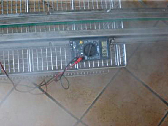
The working nozzles are earthed in the working chamber, electrically non-conductively connected to the boiler and suspended in the working chamber in an insulated manner. The steam supply from the boiler to the nozzle is always electrically connected in non-conductive steam hoses. For safety reasons, the boiler is always earthed to prevent any known negative charging to high voltage values. Figures 5 and 6 show views of the basic unit for the tests.
Investigations into heat transfer during condensation of superheated steam and saturated steam under atmospheric pressure were not carried out as part of this work. The results of the research work of Prof. Dr.-Ing. M. Jakob and Dr.-Ing. S. Erk [1] were used for the experiments.
In the tests, they proved that the heat transfer of dry superheated steam to systems under atmospheric pressure is not inferior to that of saturated steam. The degree of quality of the heat transfer is better for superheated steam than for saturated steam.
As the wall temperature rises, the amount of heat released by the steam decreases, even if the wall temperature exceeds the saturation temperature of the steam. However, this is not sudden, but steady. Similarly, the start of boiling does not cause a sudden change in the heat transfer from the pipe wall to the cooling water.
The heat transfer increases with increasing steam velocity. The highest achievable heat transfer with saturated steam was 175000 kcal.m-2.h-1 (steam velocity 70 or 110 m/s, temperature of the pipe wall 80 °C or 82.5 °C). If significantly poorer heat transfer is observed with air- and oil-free superheated steam, the reason is primarily to be found in gas precipitation, wall coating or the like on the side of the liquid absorbing the heat.
In technical applications, care must therefore be taken to ensure that the heat flux densities are well below the transition point between bubble and film boiling. For the medium water, the critical heat flux density is 1000 kW/m2. Steam boilers should be designed so that a heat flux density of 300 kWp/m2 is not exceeded. The transition from bubble boiling to film boiling is reduced by oils or a high salt content in the boiler water.
As superheated steam is less damaging to the system components than wet steam and also means less energy loss for the cleaning processes and fewer components in the pipework, I carried out my tests with superheated steam between 140 °C and 180 °C at the steam boiler outlet. All tests were carried out with DI water from a mixer tap with subsequent mechanical filtration to 10 µm and with tap water with a hardness of 6 °dH. The vapors were always pumped back into the storage tank and then cleaned and pumped into the boiler.
The steam escaping from the steam boiler was superheated in the working nozzle. Hot air from the environment is used to heat the nozzle and the air drawn in up to 350 °C, producing dry steam. Alternatively, the nozzle body is heated up to 600 °C using heating cartridges from the plastics industry.
|
Test description |
Wet chemical solution |
Superheated steam |
Remark |
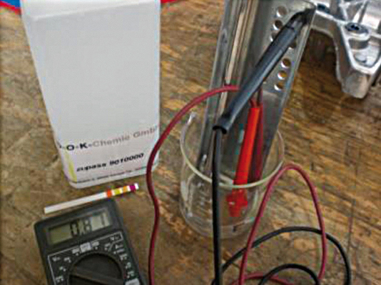 |
pH value of the solution = 3 Black wire is negative pole, red wire is positive pole Solvent is tap water with water hardness 8°d(H) Measured voltage between component and solution is 870 mV |
The surface is positively charged with 870 mV; |
|
 |
pH value of the solution = 10 Black wire is negative pole, red wire is positive pole Solvent is tap water with water hardness 8°d(H) Measured voltage between component and solution is 520 mV Hakupur 735-1 |
The surface is positively charged with 520 mV; |
|
 |
Red cable is negative pole, black cable is positive pole Solvent Tap water with water hardness 8°d(H) Measured voltage between component and solution is -648 mV |
The surface is positively charged with 520 mV; the surface is slightly "pickled", comparable to a slightly acidic solution. The polarity of the measuring device is reversed, therefore the sign changes |
Electro-galvanic voltage of the steam
To understand this physical property of water, the effect of wet-chemical cleaners, acidic and alkaline, is compared with the effect of superheated steam.
If water in a boiler is heated up to 200 °C, the steam and the surrounding boiler become negatively charged. The boiler is not earthed. The voltages can be detected using commercially available DC voltmeters.
If the steam is fed through an electrically non-conductive pressure hose to the discharge nozzle and exits the nozzle without first making contact with earth, the steam jet is still negatively charged directly at/in the nozzle outlet. After 5 mm to 10 mm of free jet, the steam is neutral and then becomes positive. The level of charge depends on the nozzle contour and is primarily determined by the outlet pressure in the boiler. Voltages between 0 V and 1200 mV were measured in the experiments in this work. This voltage is dissipated on the irradiated surface as the component is fixed to earth. As a result, the foreign particles are discharged/charged from the surface and repel from the component surface. The direction of flight of the free particles is determined by the vapor volume. Steam itself can discharge the foreign particles, but due to the expansion when leaving the nozzle, the steam pressure quickly drops to ambient pressure. As a result, the possible conveying capacity decreases with increasing nozzle distance. Ambient air is generated and used as a traction medium to safely remove the foreign particles.
In aqueous-alkaline cleaning, the cleaners generate the electrical voltage of the cleaning solution against the system, the component. Cleaning is also a galvanic process. The voltage behavior is shown in Table 1 for comparison.
For reproducible cleaning, the surface of the component to be cleaned is sprayed with water from the collection tank at a temperature of 60 °C before the steam is applied at 170 °C. This causes the dirt particles to dissolve and become electrically activated.
The superheated steam generates 140 °C to 150 °C on the component surface, the wet dirt surface is electrically charged and the dirt particles are repelled from the component surface. The electrical-static adhesion between the dirt particles and the component surface is removed and the dirt particles, which are now floating, are sucked away by the negative pressure in the environment.
Please note: If the component is moved towards the steam nozzle, the loosened dirt particles have a kinetic energy in the direction of the relative direction of movement. The superheated steam cannot generate this kinetic energy, which is why additional extraction with indoor air is required. A water jet pump, injector nozzle or medium-pressure compressor mounted in front of the steam nozzle extracts the stray dirt particles.
Part 8 deals with further details of dry steam cleaning, such as drying the cleaned component, collecting particles and the importance of water hardness.
