The ever-increasing mechanical and optical demands placed on coated plastic parts, coupled with the need to reduce prices and therefore costs, present manufacturers and coaters with ever-increasing challenges. Even a small proportion of rejects can make the difference between profitable and unprofitable. It is therefore essential to quickly identify the causes of defects. In the following, typical and sometimes unusual defects in the coating of plastics will be presented and the analytical clarification of the causes of the defects will be described. These are all cases of damage for which DFO Service GmbH was commissioned to analyze and determine the causes.
Failure pattern cracking
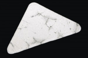
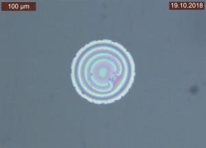
In the first case, cracking occurred on coated polycarbonate components for automotive interiors in the area of the symbols (see Fig. 1). These areas are lasered free after the initial coating and then the entire component is overcoated with a black UV clear coat. At the request of DFO, various processed components were provided for examination, including raw parts, coated and lasered parts, components painted with clear coat only and components with the defect pattern that were coated and processed according to the standard process. As translucent inlets are inserted into the components in the area of the symbolism, it was suspected that these were defective or that the cracking was caused by the laser process.
The cause could already be clearly identified during the light microscopic examination of all component variants: Both the uncoated parts and the component that had been coated and lasered in the inlet area but not overcoated with clear lacquer showed no cracking whatsoever. In contrast, the unfinished part, which was only coated with the UV clear coat, showed cracking identical to the defect pattern not only in the area of the inlets, but also on the entire component surface. A glance at the safety data sheet for the UV coating revealed that it contained a relatively high proportion of butyl acetate. However, the PC components used were not sufficiently resistant to this solvent, so that cracking occurred directly during coating with the UV clear coat. The defect was then only visible in the area of the inlets because, on the one hand, this area was translucent and backlit, which significantly increased the visibility of the cracks. Secondly, the black coating was present on the rest of the component at the time of clear coating. This was resistant to butyl acetate.
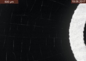
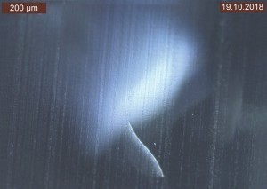
In a second case of cracking, switch panels, also made of polycarbonate, were primed in white with 2K polyurethane paints and topcoated in black. The raw parts were manufactured in Germany and then sent to Asia for coating with the specification of the paint systems to be used. Here, too, an area was laser-cut to achieve a partially translucent symbolism so that it could be backlit when installed. After a short period of use, fine cracks became visible during backlighting (see Fig. 2) and complaints were made as a result.
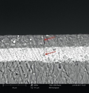
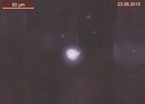
To localize the cracks precisely, cross-sections were first made using a microtome. The cracks themselves could then only be visualized using a scanning electron microscope (SEM) (Fig. 3); they were not visible under a light microscope.
Although the cracks ran through both coating layers, they did not reach the substrate. A substrate defect or cracking in the substrate could therefore be ruled out.
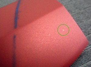
2K polyurethane coatings show excellent chemical resistance, provided they are sufficiently cured. However, a wiping test with a cloth soaked in isopropanol showed a different picture: the coating could be wiped off the components almost residue-free with little effort. A clear cracking of the coating could be observed (Fig. 4).
An IR spectroscopic examination of the coating provided information: the red spectrum in Figure 5 shows the absorption bands of the black coating, the blue spectrum those of the white coating. Both showed a clear undercrosslinking, recognizable by the intensity ratio of the two characteristic peaks at the wavenumbers 1685 cm-1 and 1721 cm-1. Both polyurethane coatings were so clearly undercrosslinked that it could be assumed that no hardener had been added at all.
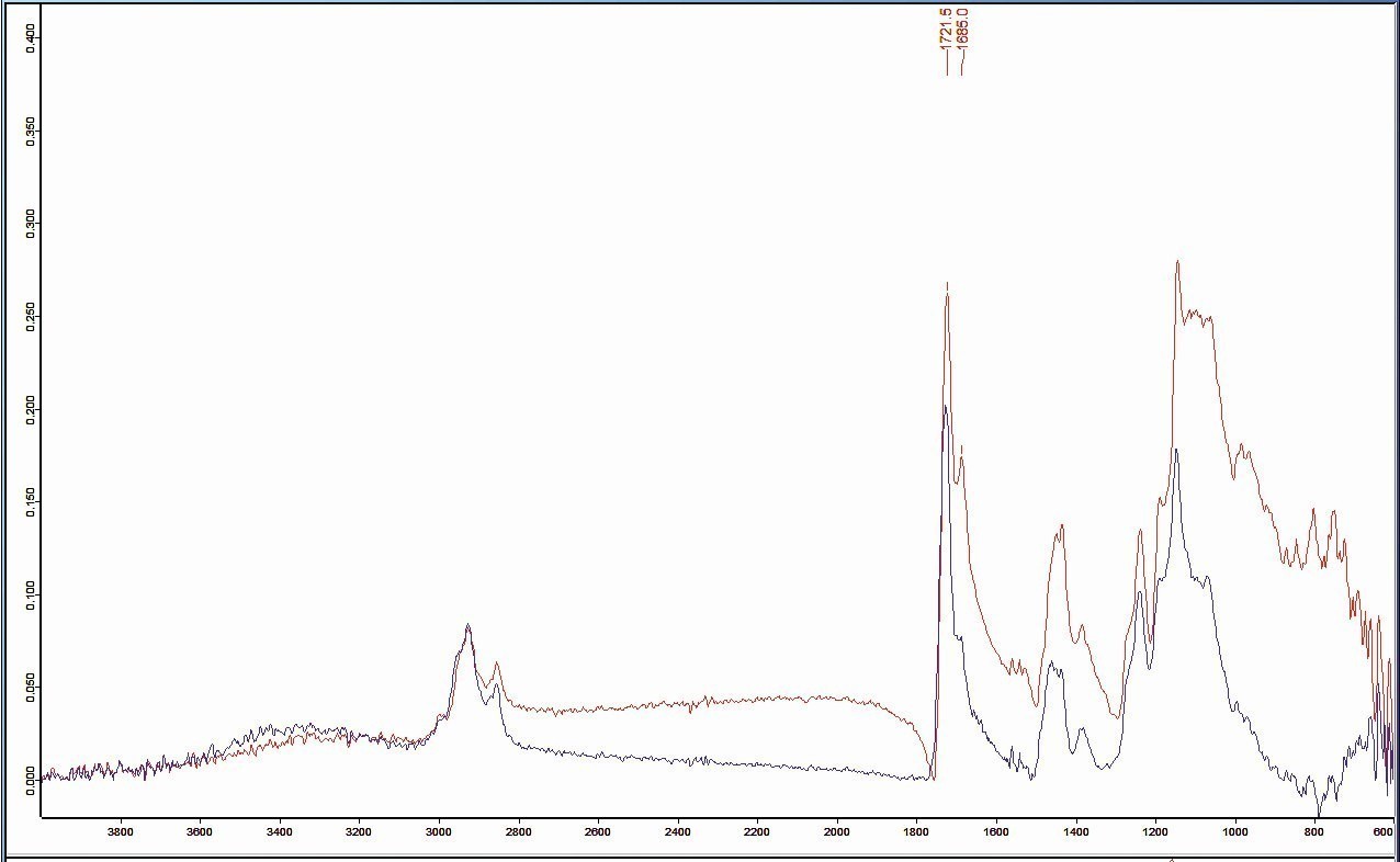 Fig. 5: IR absorption spectra of the coating (red spectrum: black layer; blue spectrum: white layer)
Undercrosslinked coating systems have neither sufficient mechanical-technological properties (elasticity, adhesive strength, etc.) nor high chemical resistance and can even be dissolved.
How did the cracking occur? The base coat of both paint systems contained high levels of butyl acetate. After the white primer - obviously only the base coat - had been painted, it was unable to crosslink due to the lack of hardener. The subsequent coating with the black top coat - again, only the base coat - led to cracking of the non-chemical-resistant primer due to the butyl acetate it contained. Subsequent mechanical stress on the switches in daily use (pressure switches) caused cracks to propagate from the primer to the already less elastic top coat. Solvent-based cleaning agents, such as glass cleaner, may have contributed to the increase in defects.
The third case of damage shows that even in the field of plastic coating, supposed coating defects often enough actually turn out to be substrate defects. In this case, DFO Service GmbH was commissioned to examine coated plastic components that showed abnormalities in the hydrolysis resistance test. In addition to very isolated bubble formation, the anomalies were described as "glistening spots", which appeared very differently bright depending on the viewing angle and illumination.
 Fig. 6: "Glistening spots" defect image in top view after water storage (92 °C for 48 hours)
By means of water storage at 92 °C for 48 hours, the defect pattern could be reproduced several times with different coating structures (see Fig. 6).
Subsequent storage in the oven for 30 minutes at 80 °C significantly reduced the defect pattern, so that water inclusions were assumed (Fig. 7).
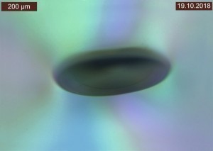
By varying the filter settings, interference phenomena could be visualized under the light microscope, which sometimes appeared as dark, elliptical effects (Fig. 8) and sometimes as circular, spherical effects (Fig. 9).
The cross-sectional examinations did not show any abnormalities in the coatings, but the same interference phenomena that were already visible in the top view were noticeable deep in the substrate (see Fig. 10).
Finally, the defects were fractures or cracks in the plastic, which could also be detected in completely uncoated components after the hydrolysis resistance test. The plastic used was therefore not hydrolysis-stabilized, as assumed by the client.
Bubble formation defect pattern
If bubbles form on a coated component, there are numerous possible causes. This defect often only becomes visible after some time, depending on its origin. The blisters often appear after a longer period of time in the end application, after a condensation water constant climate test or the hydrolysis resistance test.
The most typical causes here are
- inadequate mixing of 2K coating systems
- Rinsing or abrasive residues under the coating
- Inadequately pre-treated substrate surfaces (e.g. due to over-scarfing)
- Overburning in the curing oven due to excessive temperature
Somewhat more exotic causes of blistering are less common. One such cause is explained below using an example.
CFRP components manufactured in China were sent to Germany for coating with a multi-layer structure. They were transported there and back by ship. When the finished coated components arrived in China, massive blistering was detected on the components. These were shipped back to Germany as a complaint, but the defect was no longer visible there. The parts that remained in Germany after coating also did not show this defect at any time. Using light microscopy, small crystalline inclusions in the coating could be made visible across the entire component using a polarization filter (Fig. 11).
The inclusions were exposed by means of an oblique section using a microtome and further examined using SEM with energy dispersive X-ray spectroscopy (EDX). The EDX analysis showed that in addition to the "normal" paint components (carbon (C), nitrogen (N) and oxygen (O)), the elements sodium (Na) and chlorine (Cl) could also be found (Fig. 12).
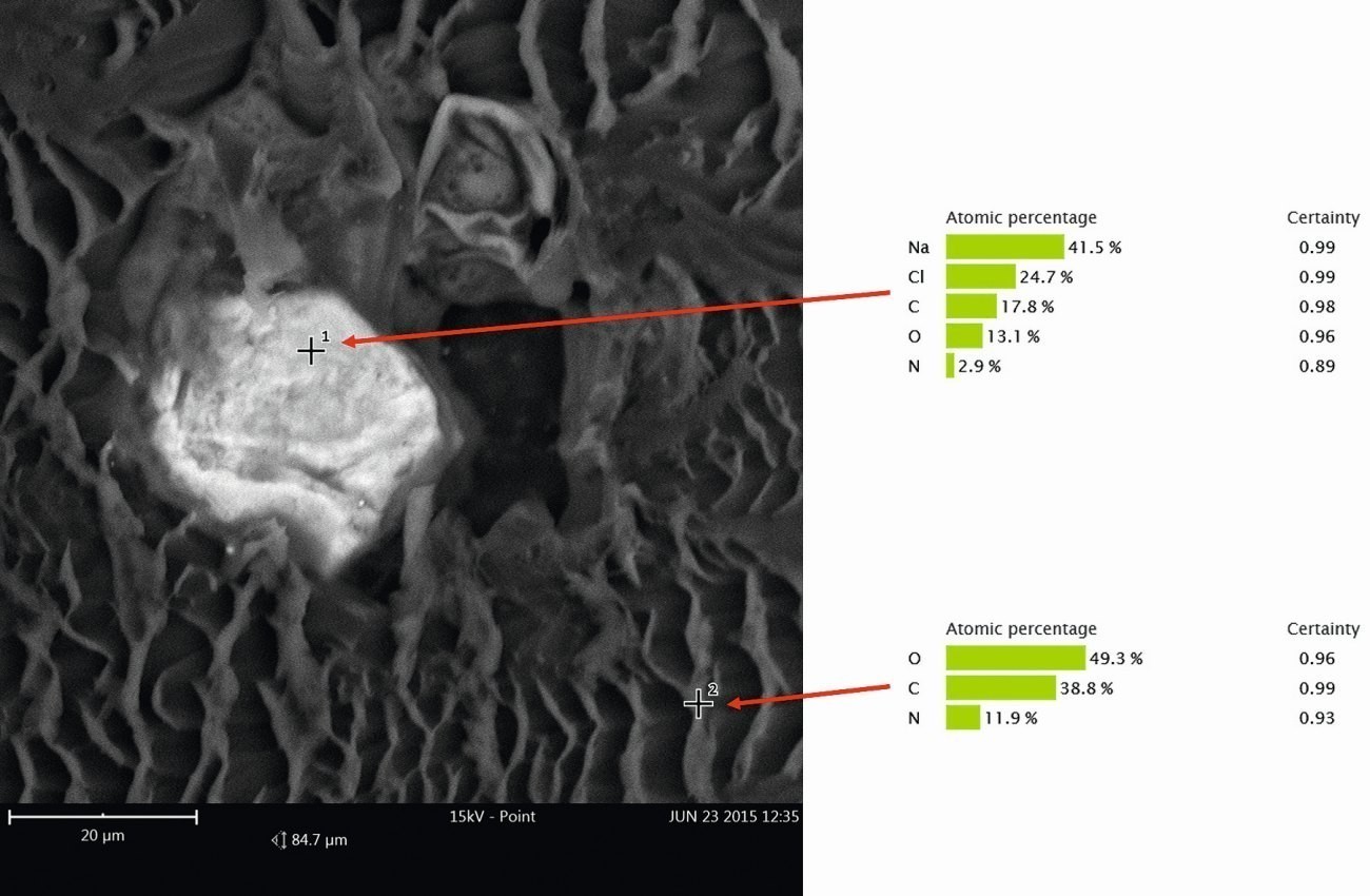 Fig. 12: Point measurements by EDX in the inclusion (measuring point 1) and in the area of the i.O. coating (measuring point 2)
The chemical compound that can be assigned to these elements is sodium chloride (NaCl). Due to the positioning of the inclusions (they are found in all layers and on the substrate), it was assumed that the NaCl had entered the coating immediately before or during the coating process. After consultation with the coater, it was possible to clarify how the salts had gotten into and under the coating. The CFRP components were sanded manually before coating. Normally, such processes are carried out with gloves, which was also the case here. However, according to the coater, after the sanding process the employees checked the sanded surface with their bare hands to "feel" whether the sanding had been sufficiently smooth. This meant that the contamination with NaCl could simply be traced back to residues of hand perspiration, which typically contains high quantities of NaCl.
But what does this have to do with blistering? Sodium chloride is a hygroscopic substance, so it tends to absorb water. Since an organic coating always has a certain water vapor permeability, enough water can migrate to the sodium chloride to cause an increase in volume and consequently the formation of bubbles, especially at high humidity.
This also explains why the defect was only visible in China after transportation by sea. On the high seas, the components were exposed to high humidity over a long period of time. Back in Germany, the water contained in the bubbles had escaped again at low humidity and the bubbles had regressed.
"Spots" defect pattern with increased gloss level
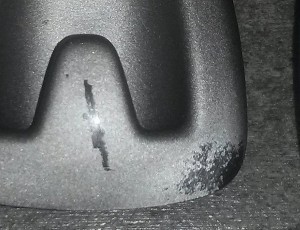
The following case concerned the coating of plastic components with a colored basecoat and a matt 2K polyurethane clearcoat. Here there were isolated circular spots a few millimeters in size with an increased gloss level, which were described as "spots" (see Fig. 13).
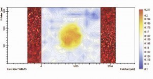
No inclusions or irregularities in the pigmentation could be detected under the light microscope, neither in top view nor in cross-section. The brightening in the defect area was only due to the higher gloss level. For further analysis, the defect area was examined over a large area using IR spectroscopy. A grid with over 300 measuring points was laid out over the defect area (Fig. 14). This allowed the IR spectroscopic differences between the defect area and the OK area and a corresponding local demarcation to be shown.
To illustrate the IR spectroscopic difference between the error range and the OK range, the difference in intensity of the individual absorption spectra at the typical wavenumber for isocyanate of 1686 cm-1 was shown in false colors over the entire measurement range. A clear increase in band intensity can be seen in the error range (yellow-orange), while the band intensity in the OK range is constantly lower (blue-white). Consequently, it could be assumed that a significantly higher amount of isocyanate was present in the defect area. Isocyanate is used as a hardener in 2K polyurethane clear coats.
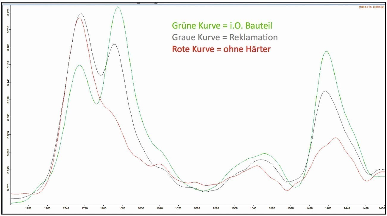 Fig. 16: IR spectroscopic comparison of different coatings
Local over-concentrations of hardener (isocyanate) can occur, for example, due to insufficient mixing of the base coat and hardener.
Static mixers are typically used for 2-component coatings. If these are too short, the mixing distance is not sufficient for homogeneous mixing.
In addition to a number of other factors, the difference in viscosity between the hardener and basecoat can influence the mixing distance required for homogeneous mixing.
Furthermore, valves and nozzles that do not close properly can lead to drops of coating material or base coat or hardener escaping before or after the actual coating, which can lead to "spitting" on the coating. The result is over- or under-crosslinked areas of the coating, which can typically exhibit local differences in gloss level.
Defect pattern loss of adhesion
There can be several reasons for loss of adhesion in coatings. If there are impurities on the substrate surface, such as residues of release agents, sanding dust, fingerprints, etc., these interfere with the adhesion of the coating to the substrate. An insufficiently cured coating does not achieve the mechanical-technological target properties and can therefore also lead to a loss of adhesion. Another influencing factor is the wettability of the substrate, which is characterized by the free surface energy. For sufficient wetting of the coating film, the free surface energy of the substrate must be greater than that of the coating material in order to enable sufficient adhesion.
These and other possible causes of loss of adhesion repeatedly pose challenging questions for DFO in the field of damage analysis.
In the following case, plastic parts coated with a polyurethane-based 2K paint suffered from loss of adhesion. The DFO was provided with defective components (see Fig. 15) and components without loss of adhesion to investigate the causes.
The comparative IR spectroscopic investigations of the coatings of the components without loss of adhesion and the components with complaints revealed clear differences in the intensity of the two peaks at approx. 1680 cm-1 and 1730 cm-1 in the spectra. Their intensity ratio is inverse in the samples examined, whereby the peak of the wavenumber 1680 cm-1 is clearly attenuated in the complaint sample (Fig. 16). These two peaks can typically be assigned to a polyurethane compound. The peak intensity of the wavenumber 1680 cm-1 was very low in a coating sample prepared in the laboratory, in which no hardener was added to the coating as a test.
This suggested that there was an incorrect mixing ratio between the hardener and the base coat of the 2K lacquer. If there is too little hardener in a two-component coating, the cross-linking reaction cannot take place completely, which results in insufficient adhesion, among other things.
In the event of a complaint, a very simple test can be carried out to quickly check whether there may be insufficient curing: This involves rubbing the coated surface with the solvent isopropanol. If there is no change, the coating is fully cured. If, on the other hand, the coating "dissolves", it can be assumed that the coating has not cured sufficiently. If sufficiently cured, a 2K coating is resistant to this stress. Another case of damage with the defect pattern "loss of adhesion" required a different analytical approach. Coated and partially laser-cut plastic components for automotive interiors showed large-scale loss of adhesion (Fig. 17). Although the defect pattern could be narrowed down to just one batch of paint, there were still disputes about the cause of the defect, as only a few percent of the components were affected. According to the paint manufacturer, nothing relevant had changed in the paint formulation with regard to adhesion. In this case, IR spectroscopic examinations of the coating did not reveal any abnormalities compared to the coating of non-defective components.
In the case of adhesion defects or delamination of the coating, the parting plane is always of analytical interest. In this case, therefore, both the underside of the coating and the component surface in the delamination area were examined using ToF-SIMS (time-of-flight secondary ion mass spectrometry). This analytical method makes it possible to detect even the smallest traces down to monomolecular layers of a substance. In this way, a modified polydimethylsiloxane (PDMS) was detected on the underside of the coating. This alone was not initially conspicuous as such PDMS, e.g. in the form of a flow additive, are typical coating components. However, large quantities of PDMS were also detected on the component surface in the delaminated area. No PDMS was detected on uncoated raw parts from the same production batch, but stearates and palmitates were detected. Others concluded that PDMS could be ruled out as the cause, as it was a coating component, and that the stearates and palmitates must be responsible for the defect pattern.
A little logic and physical imagination helped to disprove this thesis. Stearates and palmitates could be ruled out as the cause of the defect, as they would also have caused the problem in other paint batches.
Meanwhile, the PDMS used in the affected coating system could very well be the cause of the defect. Leveling additives based on PDMS have a surfactant structure, i.e. a non-polar and a polar part in the molecular structure. When used in a coating system, they have a surface-active effect and thus reduce the free surface energy of the coating, which should lead to better flow of the coating. It is known that an excessive amount of such surfactant substances leads to the so-called critical micelle formation concentration (CMC) being exceeded. This can lead to the formation of micelles of PDMS, which in turn attach to each other or form lamellar structures at the phase boundaries, e.g. coating/substrate (Fig. 18).
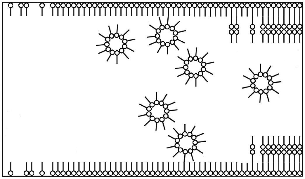 Fig. 18: Positioning and alignment of surfactants in a liquid (e.g. paint) at the phase boundaries
The individual layers of PDMS have no or a weak adhesive bond to each other. Consequently, delamination of the coating from the substrate can occur in these areas. But how did an excessive amount of PDMS come to be present in the affected coating batch? A closer look at the events during the period in which the defect occurred revealed that the formulation of the affected batch did indeed deviate from the standard formulation. Just under 1% matting agent was removed from the formulation to adjust the gloss level. However, the statement that this was a non-adhesion-relevant change to the recipe was unfortunately not correct. As the matting agent used was a solid, a relevant proportion of the available surface was removed, at whose phase boundary to the coating the PDMS could align itself. The excess PDMS now led to the CMC being exceeded and ultimately to the adhesion failure. Adequate adjustment of the additive quantity when changing the formulation would have avoided the problem.
"Stippling" error pattern
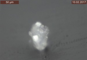 Fig. 19: Inclusion in the coating in top view (500x magnification, polarization filter 90°)The most plausible cause is not always the actual cause of the "speckling" defect. It is easy to talk about "dirt inclusions" in the coating, whereupon all employees usually go in search of impurities on the components, contamination in the paints or in the painting periphery. Sometimes, however, the source of the "specks" is only recognizable at second or third glance.
In the case of components with a high-gloss black coating, specks formed in the coating. The problem was already evident at the start of series production and occurred continuously and homogeneously on all component surfaces. However, the usual measures, such as changing paint batches, cleaning the paint booth or checking the cleanliness of the components, did not lead to any significant improvement. As a result, the component itself became the focus of suspicion.
However, the first light microscopic examinations from above quickly showed that numerous crystalline inclusions in the coating were the cause of the defects (see Fig. 19).
The inclusions were first exposed by means of an oblique section using a microtome and then examined using EDX. In addition to the typical coating elements carbon and oxygen, a large number of foreign elements such as sodium, potassium, sulphur and chlorine were detected, which could not initially be assigned. In order to be able to assign the foreign elements, a deeper insight into the history of the paint shop was required. After numerous discussions with the plant operator, it emerged that there had been a local fire in the immediate vicinity of the paint booths years previously. When more detailed enquiries were made about this incident, it emerged that the fire had been extinguished using portable powder fire extinguishers. A quick search on the ingredients of powder fire extinguishers revealed the origin of the coating inclusions: Class BC extinguishing powders, for example, are composed on the basis of potassium sulphate and sodium hydrogen carbonate. Class D extinguishing powders often contain sodium chloride.
Why had the previous measures, especially the cleaning of the paint booths, not led to a reduction in the defect rate? The release of even small quantities of extinguishing powder can lead to considerable consequential damage. Extinguishing powders are particles just a few micrometers in size that can become lodged in ventilation systems, filters and application technology. In addition, the extinguishing powder used can absorb and carry away components of the source of the fire. Even years later, these particles can still be found and cause defects. In such cases, more extensive cleaning by specialist companies is usually required.


