
In order to develop a method for in-situ observation of the growth of electrodeposited dispersion layers, three consecutive experimental set-ups are presented in which the development is observed using a digital microscope. Dispersion layers with a silver matrix, deposited from a cyanide electrolyte, are used as example systems. Both electrically conductive (polythiophene-functionalized sulphur particles) and non-conductive particles (diamonds) are used as dispersoids. The former play an important role in the galvanic production of sulphur-based battery electrodes, the latter in wear protection, on tools or in tribological applications, for example.
Electroplating applications can be found in many manufacturing processes and it is difficult to imagine our level of technological development without electroplating. Electroplated coatings are generally divided into decorative and functional coatings. One type of coating that is primarily used in the area of functional coatings is dispersion deposition [1].
In this process, dispersoids (e.g. particles) are simultaneously incorporated into the metal layer growing as a matrix during (electro)chemical deposition. This allows the properties of the metal and the dispersoids to be combined, thus optimizing tribological properties such as friction coefficient and wear [1]. Another field of application for dispersion layers is saw wire for cutting monocrystalline or polycrystalline silicon [2, 3]. The use of dispersion deposition is also conceivable in future industries such as battery technology [4, 5]. For example, its application has been researched for several years as part of the combined composite electroforming process developed by our working group at Aalen University for the production of complete battery electrodes [6-11].
In principle, a distinction can be made between electrically conductive and non-conductive particles. Models have already been developed for both in the past, which, adapted to a model system in each case, allow modeling of the intercalation fractions of dispersoids in the layer [1]. Guglielmi [12] used non-conducting dispersoids for his work. His model is based on the assumption that the incorporation of a particle into the coating is preceded by a two-stage adsorption process. Bazzard and Boden [13] carried out studies on dispersion deposition with conductive dispersoids. They observed dendritic growth of the layers. This is due to the electrical conductivity of the particles: If a particle comes close to the cathode surface, it increases the electric field strength in this area and thus the local current density. If the particle then touches the growing layer, it will grow directly around it. In contrast to non-conductive dispersoids, which are embedded from the base to the tip, a layer is spontaneously deposited on the entire particle after contact. In addition, further models have been developed over time that take into account more and more aspects relevant to the intercalation mechanism [14-18].
As with any coating, the quality of the coating plays a decisive role in dispersion deposition. In order to check this, coated substrates are usually randomly inspected for quality defects after coating. This means that defects can only be detected on the result - the finished coated component. If the process stability is suboptimal, this leads to a high level of rework or increased rejects, but in any case to increased costs. It would be advantageous if components could be inspected in-situ during the coating process. This would not only allow defects to be detected at an early stage, but the process could also be corrected in real time. This article represents a first step in this direction and is primarily intended to improve our understanding of the processes involved in dispersion deposition. A method is presented, still on a laboratory scale, of how the growth of dispersion layers can be observed in-situ via digital microscopy with the aid of a suitable experimental set-up.
Selection of the process
Due to the different growth modes of electrically conductive and non-conductive particles, one type from each area was selected as a model particle. As non-conductive particles, diamonds are relevant, for example, for wear protection coatings, tribological applications to increase the static friction coefficient or for coating saw wires. Diamonds (d50 = 29 µm; Element Six, County Clare, Ireland) are therefore used here as an example. According to Wu et al [19], sulphur particles functionalized with polythiophene are used as conductive dispersoids. Sulfur particles functionalized in this way are used in the aforementioned composite electroforming process to build novel sulfur cathodes [4-11] for Li-S cells. Since the in-situ observation is to be carried out using optical light, the electrolyte must be as transparent as possible, which applies to most cyanide baths.
In order to prevent vapors from rising due to increased temperature and depositing on the microscope, a process that can be operated at room temperature should be selected, which also has almost 100% efficiency in order to prevent the development of hydrogen that would interfere with observation. Cyanide silver electrolytes typically meet these requirements. Silver, like all coinage metals, is also known to be suitable as a matrix for dispersion deposition. Table 1 shows the electrolyte composition used.
Development of the experimental setup
A digital microscope (VHX 6000, KEYENCE Deutschland GmbH, Neu-Isenburg, Germany) is used for in-situ observation. This offers the advantage of being able to illuminate a transparent flow cell with a substrate of suitable geometry in different ways, e.g. coaxially or with a ring light. The flow cell is made of glass. This means that an additional light source (transmitted light) radiating upwards through the coating cell can be used. A pump (PERIMAX 12, Spetec GmbH, Erding, Germany) is used to prevent sedimentation of the particles. It pumps the particle-containing electrolyte from the storage container into the coating vessel and from there into a collection container. This also generates the convection that is relevant in practice. The voltage source is a galvanostat (built in-house by Aalen University, Aalen, Germany), which is connected to a multimeter (Voltcraft VC 840, Conrad Electronics AG, Wollerau, Switzerland) for fine adjustment of the current. A silver wire (d = 1.5 mm, 99.99 % silver, Martin Wagner, Sonnenbühl, Germany) acts as a soluble anode. Figure 1 shows the schematic test arrangement.
 Fig. 1: Schematic experimental set-up for in-situ observation of dispersion deposition
| Component | Concentration in g/l |
| Potassium dicyanoargentate(I) | 100 |
| Potassium cyanide | 95 |
| Potassium carbonate | 55 |
 Fig. 2: Circuit board cut-out with fixing and contacting after coating A drip tray, which is not shown for better clarity, serves as protection against an accident. The storage and collection containers are placed in the drip tray during the experiments. Furthermore, the magnetic stirring plate under the storage container, over which the solution is stirred using a magnetic stirring rod to keep the particles in suspension, is not shown. A transparent plastic film is placed between the object table and the coating cell to protect the object table from contamination with electrolyte. The real test arrangement can be seen in the first picture of this article. The numbering corresponds to that in Figure 1. The described experimental set-up is used for all experiments.
In order to be able to observe the layer growth in the horizontal as well as in the vertical plane, individual pieces with metallized holes on the top side only (D hole = 2.0 mm) are cut out of printed circuit boards and used as substrates (see Fig. 2). For the coating, a simple polycarbonate holder is made for clamping the substrate.
To protect the objective of the microscope, a Petri dish is placed on the screw heads and fixed to the edge of the vessel with plastic blocks. This arrangement is shown schematically in Figure 3.
A photo of the arrangement of the coating cell is shown in Figure 4. To ensure clarity, some elements such as the plastic blocks with tubes and the silver anode wire are not attached.
This experimental set-up is used for dispersion deposition with sulphur particles. Incident light (illumination from above, here as ring light) and transmitted light (additional illumination from below) are used to illuminate the substrate. In order to be able to observe the coating process in the entire drilling area, work is carried out without magnification.
 Fig. 3: Schematic insert for the initial internal structure of the coating cell
To improve the reproducibility of the results, the test set-up is being further developed. New substrates and a new substrate holder were designed for this purpose. The new substrates are again printed circuit boards with holes (EDA Center of Aalen University, Aalen, Germany), but with a fixed layout. The diameter is reduced to d = 0.5 mm in order to be able to operate with digital magnifications. To homogenize the electric field in the drilling area, a 2 mm wide copper layer remains around the hole as well as a conductor track 3 mm wide and 15 mm long as an auxiliary cathode. A holder is developed and 3D printed for the new substrates and the Petri dish as lens protection. The dimensions are adapted to the dimensions of the coating vessel. The design of the new holder with circuit board is shown in Figure 5.
 Fig. 4: Structure of the coating cell without some elements
 Durchführen des Anodendrahts und des Kathodenkabels zur Fixierung; 3–5) Herausführungen aus der Beschichtungszelle in drei getrennten Kanälen; nicht gezeigt: metallische Fittings im Austrittsbereich der Kanäle zum Aufstecken der Schläuche; Pfeile: Absaugrichtung Elektrolyt; 4) Öffnung zum Freispülen der Substratoberfläche; 5) Einströmung von Vorratslösung") Fig. 5: 3D-printed holder with new substrate and numbering of the individual channels: 1, 2) Feed-through of the anode wire and the cathode cable for fixing; 3-5) Outlets from the coating cell in three separate channels; not shown: metal fittings in the outlet area of the channels for attaching the hoses; arrows: Electrolyte suction direction; 4) Opening for rinsing the substrate surface; 5) Inflow of supply solution
Fig. 5: 3D-printed holder with new substrate and numbering of the individual channels: 1, 2) Feed-through of the anode wire and the cathode cable for fixing; 3-5) Outlets from the coating cell in three separate channels; not shown: metal fittings in the outlet area of the channels for attaching the hoses; arrows: Electrolyte suction direction; 4) Opening for rinsing the substrate surface; 5) Inflow of supply solution
The geometry of the holder also allows the Petri dish to be inserted over the substrate to protect the objective and is thus fixed in place. Figure 6 (left) shows the cylinder under the circuit board in detail. This is hollow so that microscopy can also be carried out using transmitted light. This is also intended to prevent particles from accumulating under the substrate and thus obstructing the light entering from below. Two further holes are made in the hollow cylinder through which the anode is guided. This is shown in Figure 6 (right), where only one of the two holes is visible. The top view in Figure 7 shows the fully assembled coating cell.
 sowie ein vertikaler Schnitt durch die Halterung und die Kanäle (rechts)") Fig. 6: Top view of the holder (left) and a vertical section through the holder and the channels (right)
Fig. 6: Top view of the holder (left) and a vertical section through the holder and the channels (right)
Layer growth with sulphur can be observed in-situ at higher magnifications with this experimental setup. Here again, incident and transmitted light illumination is used. Due to the higher density of the diamonds, they would sediment in the tubes and therefore cannot be conveyed with the existing experimental setup. In order to still be able to feed the particles, the particles are not pre-dispersed in the storage container, but are instead placed in a 250 mL separating funnel with electrolyte. Thus, in the modified test arrangement, the particle-free electrolyte is pumped from the storage container through a newly inserted T-piece (see Fig. 8), via which a suspension with a high particle content is added, into the coating cell. The T-piece is connected to the separating funnel. The flow of particles can be adjusted qualitatively using the tap on the separating funnel.
 Fig. 7: Top view of the fully assembled coating cell
 Fig. 9: Wire substrate soldered to the circuit board with soldered cable for contacting
In addition to the substrates mentioned above, wire substrates are also coated as a starting point for the industrial application of wire coating with diamonds. For this purpose, a copper wire (d = 0.05 mm, Heinrich Stamm GmbH, Iserlohn, Germany) is placed over a metal-free hole in a printed circuit board and soldered on. This is shown in Figure 9. As with the test set-up for dispersion deposition with sulphur, incident and transmitted light are also used here. In addition, experiments are only carried out with incident light, as this makes it easier to differentiate between the substrate and its surroundings due to the greater contrast. The illumination with incident light is always coaxial, i.e. point-shaped.
 Fig. 8: Modified test set-up with separating funnel for the extraction of diamonds
The results
Dispersion deposition with sulphur
With the first test arrangement, it can already be shown that individual sulphur particles can be optically dissolved and their adsorption on the substrate can be observed. Figure 10 shows two exemplary images. The upper image is taken with incident light only, the lower image with incident and transmitted light.
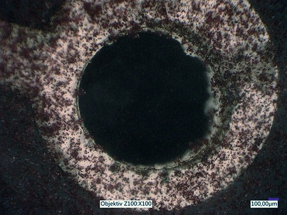

Fig. 10: Images with the first test arrangement with incident light (top) and with incident and transmitted light (bottom) with already adsorbed particles (see arrows)
By using substrates with a hole diameter reduced to 0.5 mm, it is possible to observe the dispersion deposition with sulphur particles even at higher magnification (see Fig. 11). There are 60 seconds between the images shown in Figure 11.
") Fig. 11: Images taken with test set-up 2 after different coating times with sedimented particles (see arrows)
Fig. 11: Images taken with test set-up 2 after different coating times with sedimented particles (see arrows)
Dispersion deposition with diamond
The original experimental setup proved to be quite suitable for the in-situ observation of dispersion deposition with sulphur. In order to also be able to investigate dispersion deposition with diamond, the modified test arrangement 3 is used. Figure 12 shows the chronological sequence of layer growth. The following description refers to the areas marked with red circles. Figure 12a only shows the vertical substrate surface after a coating time of 16 minutes and eight seconds. Subsequently, in Figure 12b, a diamond is adsorbed on the substrate after a further nine seconds. Figure 12c shows the diamond already half covered by the coating after a further 12 minutes and 7 seconds. In Figure 12d, it is completely overgrown after a total of 44 minutes and 18 seconds. The experimental setup is therefore suitable for the task at hand.
 Fig. 12: Time-lapse image series for dispersion deposition with diamonds
Figure 13 shows the in-situ observation of wire substrates coated with the further adapted test arrangement. The coaxial incident light of different brightness used leads to different contrasts. A stronger contrast between the substrate and its surroundings appears to facilitate differentiation. This also allows conclusions to be drawn about the deposition process, even if the process can only be observed in the relatively small focal plane here.
Conclusion and outlook:
 Fig. 13: Different illumination settings for wire coating with stronger contrast in the lower image The method presented allows the layer growth during dispersion deposition to be observed in-situ. Model systems for different substrate geometries and test arrangements are silver/sulphur and silver/diamond.
With the help of a comparatively simple experimental setup, it is already possible to optically dissolve individual sulphur particles and observe coatings in real time. A newly developed setup enables a further improvement in reproducibility by producing a 3D-printed holder and printed circuit board substrates with a defined layout. A modification of the particle feed also allows in-situ observation of dispersion deposition with diamonds. Both PCB substrates and copper wires are used here.
In order to be able to observe dispersion deposition in colored electrolytes in-situ, a flatter coating cell can be used in the future. Fundamentally different principles, such as ultrasound microscopy, are also conceivable in order to enable an extension to electrolytes with little or no permeability to visible light. This would be particularly helpful with regard to the nickel and copper electrolytes frequently used for dispersion deposition.
Literature
[1] Sörgel, T.; Meyer, J.: WoMag 9 (2013) 2, 24-33, DOI: 10.7395/2013/Soergel1
[2] Wietschel, M.; Ullrich, S.J. (Eds.): Energietechnologien der Zukunft, Erzeugung, Speicherung, Effizienz und Netze, Springer Vieweg, Wiesbaden, 2015
[3] Meyer, J.: Materialwissenschaft und Werkstofftechnik, 39 (2008), 958
[4] Kesten, O.; Wengel, A.; Sörgel, S.; Sörgel, T.: Nickel-sulphur dispersion layers on nickel foams - for use as cathode in lithium-sulphur batteries; WOMag 2016, 5, 10-16, DOI: 10.7395/2016/Soergel3
[5] Sörgel, S.; Kesten, O.; Wengel, A.; Sörgel, T.: Energy Storage Materials, 2018, 10, 223
[6] Meinhard, S.; Kesten, O.; Jäger, K.; Hägele, I.; Sörgel, T.: New insights into composite electroforming - electroforming as a key technology for high-performance accumulators, Galvanotechnik 2020, 8, 1164-1169
[7] Jäger, A.K.; Meinhard, S.; Kesten, O.; Hägele, I.; Sörgel, T.: Kompositgalvanoformung - Von der Idee zur Pilotanlage, WoMag 2020, 4, 25-26
[8] Sörgel, T.: ZVO report 2019, 1, 46
[9] Erhardt, C.; Meinhard, S.; Sörgel, S.; Sörgel, T.: Production of an innovative cathode for lithium-sulphur accumulators using electroforming processes, Galvanotechnik 2015, 106, 2396-2402
[10] Erhardt, C.; Sörgel, S.; Meinhard, S.; Sörgel, T.: Electroforming of novel, hybrid copper-sulfur cathodes for lithium/sulfur cells, ZVO-Report 2015, 5, 32-36
[11] Erhardt, C.; Sörgel, S.; Meinhard, S.; Sörgel, T.: Application of electroplating technology for a new concept to build high-performance sulfur cathodes for the next generation of lithium batteries, Jahrbuch Oberflächentechnik 2015, Vol. 71, 198-209, Leuze-Verlag, Bad Saulgau
[12] Guglielmi, N.: J. Electrochem. Soc., 119 (1972), 1009
[13] Bazzard, R.; Boden, P.J.: Trans. Inst. Met. Finish, 50 (1972), 63
[14] Celis, J.P.; Roos, J.R.; Buelens, C.: J. Electrochem. Soc. 1987, 134, 1402
[15] Fransaer, J.; Celis, J.P.; Roos, J.R.; J. Electrochem. Soc. 1992, 139, 413
[16] Hwang, B.J.; Hwang, C.S.; J. Electrochem. Soc. 1993, 140, 979
[17] Hovestad, A.; Janssen, L.J.J.: Journal of Applied Electrochemistry 1995, 25, 519
[18] Dedeloudis, C.; Fransaer, J.; Langmuir 2004, 20, 11030
[19] Wu, F.; Chen, J.; Chen, R.; Wu, S.; Li, L.; Chen, S.; Zhao, T.: J. Phys. Chem, C 115 (2011), 6057
[20] Dettner, H.W.; Elze, J. (eds.): Handbuch der Galvanotechnik, Band II, Carl Hanser Verlag, Munich, 1966
