
Pipe cleaning is a special form of dry steam cleaning. Here too, the process can achieve the required cleaning speed for pipe production and deliver reliable results. The external pipe diameters and surface structure play a subordinate role here. Penultimate part of the twelve-part cleaning series.
Tests and test results with steam engine technology models, effect of saturated steam
 Fig. 1: Adiabatic diagram model of a steam-driven reciprocating engineTheamount of heat Q₁ is continuously supplied to the water in the steam generator by the electric tube jacket heater. As the output cross-section of the steam generator remains unchanged in size and shape during the process and the pressure is kept constant with a tolerance of +/- 0.5 bar via the control of the electric heater, the temperature at the output of the steam generator T1 also remains almost constant at +/- 2K. From the starting point a, the system reaches point b after a time t₁, the steam quantity x₁ has been produced and flows via the nozzle tool into the inner pipe cross-section (χ = steam quantity).
At around atmospheric pressure of 1 bar, the pressure gauge on the steam boiler shows 0 bar, 1 kg of steam takes up a space of around 1700 liters. At a pressure of 10 bar, the pressure gauge indicates a steam overpressure of 9 bar, 1 kg of steam only has a volume of 240 liters.
If 1 liter of water (1 kg of water) is heated from 0 to 100 °C at 0 bar pressure in the steam boiler, 417.5 kJ are required. If this quantity of 1 kg of water is completely converted into steam at 0 bar pressure in the steam boiler, a further 2257.9 kJ are required. This means that 1 kg of fresh water at 0 bar pressure in the steam boiler in the test sequence requires approx. 2675.4 kJ of electrical heating energy, i.e. 743 Wh of heating energy. The losses are set to zero in this calculation.
If 1 liter of water (1 kg of water) is heated from 0 °C to 180 °C at 10 bar pressure in the steam boiler, 763 kJ are required. If this quantity of 1 kg of water is completely converted into steam at 10 bar pressure in the steam boiler, a further 2014 kJ are required. This means that 1 kg of fresh water in the test procedure requires approx. 2777 kJ of electrical heating energy, i.e. 771 Wh of heating energy. The losses are set to zero in this calculation.
Figure 1 shows the model assumptions for a piston steam engine as an overview of adiabatic lines. The area enclosed by the lines is the work, the energy in the system.
Figure 2 shows the model assumptions for a tube internal surface cleaning steam engine as an adiabatic overview. The area enclosed by the lines is the work, the energy in the system. In this model, the work acts in different processes than in Figure 1.
 Fig. 2: Adiabatic diagram model of a steam-driven internal pipe surface cleaning system The model in Figure 1 has been used several times in history and is sufficiently well known. In a modification of this model, the subject of this work is modeled in Figure 2. First, the model in Figure 1 is explained.
It is assumed that the adiabatic lines ad and bc are placed through the points a and b. The vapor expands adiabatically from point b to point c. The pressure changes from p1 to p2.
The temperature drops from T1 to T2 and the specific steam quantity changes in value from x₁ to x2. In a piston steam engine, the piston would now be moved to the starting position. The mass in the cylinder chamber is compressed along this path c to d at constant pressure p2 and constant temperature T2. The point d is reached and thus the adiabatic ad. In this phase, the vapor is condensed, the amount of heat Q2 is dissipated and the specific amount of vapor changes from x2 to x3, it becomes smaller. As the steam is not located in the cylinder chamber of a steam engine in the case we are investigating, I will use this model as a template and adapt it to my conditions.
The model according to Figure 2
The rotating body falls mechanically in free fall into the inner pipe cross-section of the starting station a at pressure pA*. The subsequent rotating bodies, which lie before the mechanical separation barrier, largely close the connection to the atmosphere with the pressure pNA**. A kind of chamber is created in which the rotating body is in the starting position in the direction of the inner pipe cross-section.
Alternatively, shooting in, i.e. an initial acceleration by shooting in the rotating body, would be conceivable. This case was tested in this work, but was not investigated further due to time constraints. In the test runs, a deviating behavior of the cleaning parameters was visible. As no significant improvement in the cleaning results was visible from the samples, this test direction was discontinued.
The contact surfaces between the start chamber and the pipe to be cleaned are electrically non-conductive. The entire length of the pipe is mounted or clamped in a non-conductive manner. To optimize and adjust the surface charge of the pipe to be cleaned, the pipe surface is connected to an adjustable DC voltage source with any polarity. The applied DC voltage is varied between 0 to 4 volts at 0 to 0.1 A in the experiments.
In our model case, the adiabatic flow from x2 via x3 to a is not caused by condensation in the inner pipe cross-section, but the vapor escapes at the pipe outletRE into the adjacent atmosphere at the pressure PNE. The vapors loaded with detached dirt from the inner pipe surfaces make their way into the condensation tank, which is designed as a collecting tank. The adjacent atmosphere is lowered to a negative pressure PNE of -100 mbar via a Venturi nozzle. In this way, the steam is safely transported as a contaminated vapor to the condensation cross-section. At the outlet of the condensation cross-section, the condensed steam drips into the collection tank. Here, demulsification causes the oils to float and settling causes the formation of a sediment consisting of chips and mineral residues. As the condensate treated by mechanical filtration at 40 °C to 70 °C is fed back into the steam generator as purified feed water at an overpressure of 11 bar, the water is circulated in a closed system. A small amount of fresh water must be added to the process. When the point x2 is reached, the rotating body moves out of the internal pipe cross-section into the open, into the surrounding atmosphere with the pressure PNE.
The calculations for the model description according to Figure 2
The latent heats δ1 and δ2 have the temperatures T1 and T2. The amount of heatQ1 is released on the "adiabatic path" from the pipe cross-section. The air, inner pipe wall and rotating body absorb this amount of heat Q1.
Q1 = x1 δ1<1>
The amount of heat Q2, which is extracted from the air in the pipe, the inner pipe wall and the rotating body in the process of moving the rotating body through the inner pipe cross-section or is "consumed" by converting the form of energy, is calculated as follows
Q2 = δ2(x2 - x3)<2>
This energy can be measured as the heating of rotating bodies, cleaned pipes and the environment. In this work, the values of this amount of energy are not determined, as the steam generator has sufficient reserves in the output and the cleaning result of the inner pipe surfaces is defined as essential for the task. There are certainly reserves for energy savings for future systems.
The work obtained Lm results from
A Lm =Q1 - Q2<3>
The index m is intended to indicate that the work ALm is close to a maximum. As in the piston machine, a Carnot cycle can be assumed for the model. In our case, the rotating body floats through the inner cross-section of the pipe, on an air-vapor cushion, in an air-vapor flow.
"The Carnot process is an ideal-typical circular process that the fluid must follow in a heat engine in order to have the same energetic state after passing through the process as at the beginning of the process. The process is reversible, i.e. the direction in which the process is run through is reversible. The Carnot process is an important basic process of thermodynamics, it is used as an ideal theoretical comparison process to investigate real processes. It is a heat-force process. It was introduced by Nicolas Leonard Sadi Carnot to investigate how efficient heat engines (especially steam engines at that time) could be. The Carnot process cannot be realized in practice, it has a model character.
The Carnot process is based on the fundamental observation that heat energy that flows from one body to the other when two bodies of different temperatures come into contact is ultimately lost for the generation of mechanical energy. Therefore, an ideal process must avoid such contacts."
(http://www.uni-protokolle.de/Lexikon/Carnot-Prozess.html )
 <4>
<4>
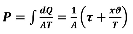
The adiabatic curve has for dQ = 0, so the value for P becomes a constant quantity. The vapor pressure in the inner pipe cross-section will be almost constant, as the loss due to condensation at the pipe outlet is continuously supplemented at the pipe inlet, it is an equilibrium.
If more than one rotating body is moved in the pipe at the same time, the equilibrium is disturbed, the temperature and pressure start to fluctuate and condensation may occur inside the pipe. Integer cycle sequences of rotating bodies moving simultaneously in the pipe certainly influence the energy loss. In test trials, no recognizable advantages of more than one rotating body in the pipe at the same time were identified. There were mechanical collisions between the rotating bodies, resulting in irregularities in the movement sequence and mechanical blockages. The use of one rotating body per revolution is therefore proposed and investigated in test series. Several balls inside the pipe disturb, even interrupt, the equilibrium between the pipe inlet and outlet. The driving flow is interrupted irregularly and follows the ball moving in the pipe irregularly.
The following applies to the adiabatic bc:
for an adiabatic curve, dQ = 0, therefore the value P = const.
For the adiabatic rate bc in the piston drive
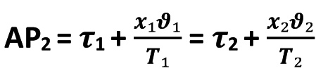 <5>
<5>
For the adiabatic ad in the piston drive
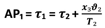 <6>
<6>
Because at point a the value x = 0
After more than 30 minutes of system operation, heating and cooling build up to an almost constant pressure in the pipe and to a stable pipe temperature when the cleaned pipe leaves the system.
Overviews of temperature, pressure and time diagrams are derived from the above statements. The reheating of dry and/or superheated steam shows significant temperature increases in the pipe cross-section with a lower percentage of heating power in the steam generator.
Figure 3 shows the energy changes and the modeling for the design of the system technology.
- Diagramm für Verdampfung bei 10 bar und Überhitzung bis auf 320 °C (die Energiemenge, die benötigt wird, um 1 kg eines Stoffes um 1 °K zu erwärmen)") Fig. 3: Temperature-specific heat capacity (amount of energy) diagram for evaporation at 10 bar and superheating up to 320 °C (the amount of energy required to heat 1 kg of a substance by 1 °K)
Fig. 3: Temperature-specific heat capacity (amount of energy) diagram for evaporation at 10 bar and superheating up to 320 °C (the amount of energy required to heat 1 kg of a substance by 1 °K)
Based on an RWE diagram from the Internet (Anwendungstechnik 1983), the experiment in this work is shown in green. In the steam generator, water is electrically heated to 200 °C. Dry steam flows continuously through the cleaning nozzles from the outlet of the steam generator, almost without water droplets. The pressure of 9.5 bar to 10 bar in the steam generator is maintained over the period of use. The steam nozzle with an intake cross-section for ambient air is heated by a hot air gun, room temperature up to 320 °C. Air drawn in and the steam coming from the steam generator are heated in the nozzle by the hot air from the hot air gun. The outflowing steam is superheated before it flows out of the Venturi nozzle and mixed with the hot air by adding it. A mixture of hot air between 20 and 320 °C and superheated steam from the steam generator is formed. The energy available for cleaning the inner surface of the pipe and for accelerating the rotating bodies is infinitely variable.
The measured cleaning results show that at the aforementioned maximum setting, a minimum of residual contamination remains in the pipe; no undesirable foreign matter can be detected on the inner surface of the pipe. A pipe batch is therefore cleaned for 6 weeks with this setting as a test. The cleaning results are stable, the system works as a system without defects.
The water circuit in the system works as described in the model. The number of rotational body cycles varies between 5 and 30 cycles.
In Figure 4, reference is made to a slide example from RWE. The green part of the curve from Figure 3 can be transferred to this diagram. Thus, the components of the supplied heat are different in value, but comparable in presence and effect on the cleaning task. The liquid heat in the steam generator (blue in Fig. 4), the vaporization heat above the liquid level in the steam generator (orange) and the overheating heat due to electrical reheating in the nozzle (red) make up the heat supplied. Evaporation at up to 200 °C results in an increase in the recoverable mechanical work, i.e. the kinetic energy required for the rotating bodies and the flow energy in the pipe interior is provided here. The waste heat area is located below the horizontal line through point 1. The liquid tanks and the pipes are the areas of high energy loss. In the tests, these areas were covered with 45 mm thick insulation from the outside.
- Diagramm für Verdampfung bei 1 bar und Überhitzung bis auf 320 °C, zugeführte Wärme") Fig. 4: Temperature-specific heat capacity (amount of energy) diagram for evaporation at 1 bar and superheating up to 320 °C, heat supplied
Fig. 4: Temperature-specific heat capacity (amount of energy) diagram for evaporation at 1 bar and superheating up to 320 °C, heat supplied
The condensation and vapor extraction areas were deliberately not insulated. Here, the heat loss must support the condensation of the vapors. The Venturi nozzle in the vapor extraction system reliably cools the vapor to 50 °C to 70 °C condensate in the collection tank. However, the collection tank is insulated to the maximum, as only feed water for the steam generator that is heated to at least 40 °C ensures a long service life for the steam generator mechanics.
In the diagram in Figure 5, the usable energies can be read off between points 1-2-3-4-1. Below the line 1-5 up to the abscissa is the area of lost energy, energy that cannot be used for the intended technology. The areas are schematically cut out in Figure 6.
 Fig. 5: Temperature-specific heat capacity diagram for evaporation at 1 bar and superheating up to 320 °C, heat supplied
The efficiency increases with increasing temperature in the steam generator and with increasing superheating. It can be seen that the energy input in the superheating range increases the efficiency more effectively. Therefore, the test experiments in this work are carried out with superheating starting from different initial pressures/temperatures.
Over the ring transport distance of the steam from the steam generator outlet to a hose length of 16 m with a clear hose cross-section of 5 mm, the steam released 10 K to 20 K into the environment. Saturated steam at 5 to 8 bar at 150 to 180 °C is available to feed the nozzles for all tests.
 Fig. 6: Efficiency from vaporization to generate mechanical work
The special design of the nozzle, a two-substance nozzle as a Venturi nozzle with a swirl effect, allows the mixing of steam with a flow velocity close to the speed of sound in the outlet cross-section. Additional full jet nozzles with inlet in the Venturi nozzle channel increase the suction effect at the air inlet. Hall air is sucked in here and mixes with the steam. The swirl of the steam flow forces the steam flow outwards. A rapidly rotating flow tube is formed. The ambient air is sucked into this flow tube.
For superheating, heated air (100 to 400 °C) is blown into the air intake cross-section with a heating air gun. The body of the nozzle takes on the temperature of the heated air and thus becomes a heated steam nozzle. This means that the outflowing steam is directly reheated and flows out at a higher temperature than when it leaves the steam generator, despite the high flow velocity. In these test series, we therefore clearly have overheated steam mixed with heated indoor air. The volume ratios of steam and air were appropriate for the appliance dimensions and the work task. The dosing and adjustment of temperature and pressure at the internal pipe cross-section inlet were therefore infinitely variable. By adding indoor air, the chamber with the rotating body received a strong steam-air impulse due to the flow resistance of the rotating body. This started the rotating body like a projectile. Over the length of the pipe, the rotating body floated through the pipe at projectile speed, largely without touching the wall. The pipe had already reached a temperature of over 100 °C after the first pass. After 3 passes, the pipe had reached steam temperature, i.e. 150 to 180 °C. This meant that 99 to 100 % of the oil, lubricating coolants, swarf and minerals had been removed from the inner surface of the pipe. The pipe was cooled to below 50 °C and dried 100% with up to five passes of the rotating body, which was driven solely by compressed air.
No additional chemicals are used in the entire cleaning process. As the test case involved V2A heat exchanger tubes with internal threads, no passivation was used. The inner surface of the tubes was cooled to room temperature by compressed air and delivered to the packaging, a wooden crate lined with foil. The surface temperature of the pipes at the time of packaging was below 40 °C, as they were wrapped in plastic film.
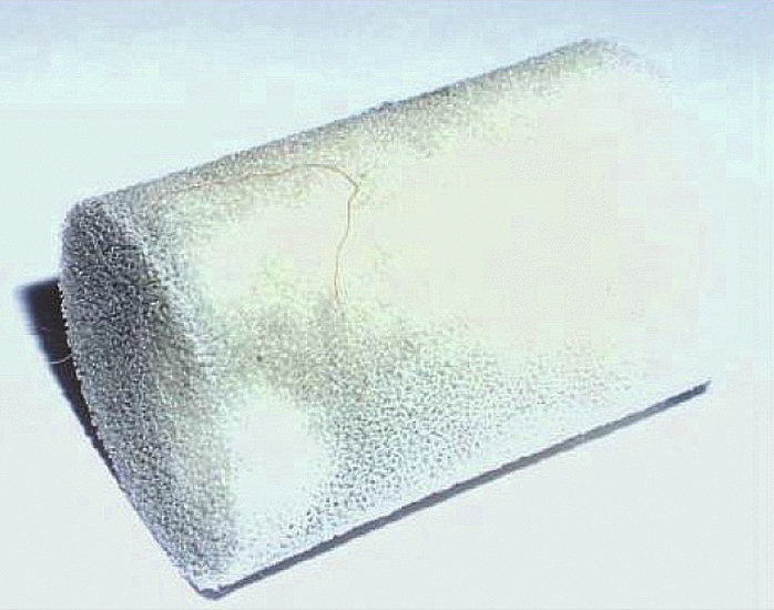
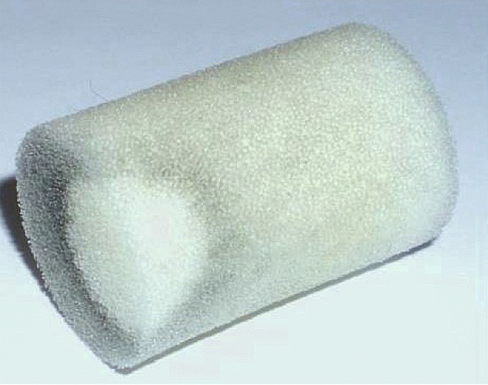
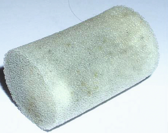
The visible test for internal cleanliness was carried out by shooting white foam cylinders once through the inner tube using compressed air, as shown in Figure 7. The white test cylinder was dry and slightly grey after the test run, the pictures show examples after 22 meters of threaded pipe with a clear width of 19 mm. Unfortunately, the laboratory test protocols are not public.
|
Test run Image Number |
Remark |
|
1 |
Heat exchanger tube thread rolled, clear diameter 19 mm |
|
2 |
Heat exchanger pipe thread rolled, clear diameter 19 mm |
|
3 |
Heat exchanger pipe thread rolled, clear diameter 19 mm |
|
4 |
Heat exchanger pipe thread rolled, clear diameter 19 mm - Test cylinder made of - white foam |
|
5 |
Heat exchanger pipe thread rolled, clear diameter 19 mm |


Technological parameters for successful surface cleaning with superheated steam
These figures are theoretically determined in two different ways. Statements on the flow velocities of the steam and the sucked-in air were also determined. The galvanic charge and the flow velocity are essential for cleaning. The temperature significantly accelerates charge separation or charge equalization between the component surface and dirt particles. Due to its physical properties, steam cannot transfer mechanical energy directly. As the steam loses approx. 1700 times its volume through condensation when it leaves the nozzle, a vacuum is always created. If the system is not sealed airtight, air is sucked in and generates the air flow. This can transport, suck in or blow away particles according to the laws of air movement. The annular gap is the "moving" annular nozzle, i.e. the shape and the cross-sectional area determine the flow behavior, determine the temperature and speed and the energy loss. A formula would have to be derived to design a system. The vapor condenses at approx. Mach 1, i.e. it rushes ahead of the sucked-in air, before the air arrives, the vapor must condense. It is not yet possible to say exactly what pressure will be achieved, although estimates and initial calculations are available. It is certain that the "cleaning flow", consisting of condensing hot steam and air, must be at least 25 m/s times 5, i.e. approx. 125 m/s and faster. This statement is based on tests with drawn wires at up to 35 m/s wire feed. The collecting station must extract the amount of air that the ball pushes in front of it, preferably a little more. Therefore, if the sample system is assumed, up to
21 m x (Dm 15 mm)2xPi/4= internal pipe volume
are moved at the speed of the ball. The ball should take less than 1 s to travel the distance, i.e. 1 s for the calculation. This results in approx. 4 dm3/sec. air, i.e. 14m3/h. It is therefore obvious to design the suction nozzle to be about twice as large in diameter with the same design as the steam nozzle. The task is solved with adjustable compressed air, between 4 and 6 bar with an 8 mm hose cross-section feed.
The following calculations result for the pipe cleaning of a heat exchanger pipe with a pipe length of 21 m:
The electrical heating power consumed was measured at max. 14 kWh in the cleaning system, for external and internal cleaning in parallel operation.
Heat exchanger pipes with a length of 21 m and an outer diameter of 22 mm were cleaned inside and outside after rolling.
Comparable statements can be made for a nozzle gap length of 180 mm with a gap width of 0.05 mm, slotted nozzle.
- What quantity of water Q? is evaporated and condensed with a consumed energy (heat) quantity Q= 14 kW h?
1. heating the water to boiling temperature (100 °C):
(Wa. = water; Da. = steam) Q1 = m(Wa.) * cp(Wa.) * (100 °C-70 °C) = Q? kg * 4.2 kJ/kg/°C * 30 °C = 17640 kJ for 140 liters of water
2. evaporation of water at boiling temperature:
Q2 = m(W a.) * Delta HV(W a.) = Q? kg * 2256 kJ/kg = 157920 kJ for 70 liters of water,
3. heating the steam from 100 to 180 °C:
Q3 = m(Da.) * cp(Da.) * (180°C - 100 °C) = Q? kg * 2.0 kJ/kg/°C * 80 °C = 9800 kJ for 61 kg of w ater vapor
4. overheating by fan heater
Q4 = m(Da.)* cp(Da.) * (300 °C - 180 °C) = 20 kg * 2.0 kJ/Kg/°C * 120 °C = 4800 kJ → Q4= 1.33 kW h.
- Total heat requirement:
Q = Q1 + Q2 + Q3 = 50360 kJ (14 kW h) → + 1.33 kW h for superheating at the steam nozzle
- Total heat requirement after reaching the operating temperatures in the test with a nozzle slot length of 180 mm and a gap width of 0.05 mm: Q = 27447 kJ (approx. 7 kW h)
- 14 kW h= Q? kg * 4.2 kJ/kg/°C * 30 °C + Q? kg * 2256 kJ/kg + Q? kg * 2.0 kJ/kg/°C * 80 °C
- Q? = 50360 kJ /(4.2 kJ/kg/°C * 30 °C + 2256 kJ/kg + 2.0 kJ/kg/°C * 80 °C )
- Q? = 50360kJ /(126kJ/kg + 2256kJ/kg + 160kJ/kg)=50360kJ / 2542kJ/kg= 19.8 kg water
- 20 liters of water per hour are converted to superheated steam, which flows through the working nozzle
- As the vapors in the working area of the steam nozzle are immediately and continuously extracted and condensed in the collection tank, fresh water quantities from the fresh water pipe are less than 5 liters/h.
Conversion to kW h (1 kW h = 3600 kJ): 50360 kJ approx.= 14 kW h
- The energy consumption is very low compared to other systems. The feed rate of the working nozzle can be up to 10 m/sec. The power limitation is restricted by the properties of the cleaned dirt. With drawn welding wire 10 m/sec have been tested, with flat surfaces with "flat nozzle 180 mm" 2 m/sec. The distance between the nozzle outlet - nozzle and surface - component should be between 5 and 30 mm, the smaller the distance the more effective the cleaning.
The galvanic charge and the flow velocity are essential for cleaning. The higher temperature significantly accelerates charge separation or charge equalization between the component surface and dirt particles.
Due to its physical properties, the high-pressure steam alone cannot generate sufficient mechanical energy to remove the dirt particles. As the HP steam loses approx. 1700 times its volume through condensation when leaving the nozzle, air is drawn in and air flow is generated. This air flow can transport the dirt particles, suck them in or blow them away.
The annular gap is the "moving" annular nozzle, i.e. the shape and cross-sectional area determine the flow behavior, determine the temperature and speed as well as the energy loss. For the project planning of cleaning systems, a calculation for different cleaning tasks will be created in further test series, which will enable the project planning of a cleaning system with the determined parameters.
The steam condenses at approx. Mach 1 in the inner diameter of the pipe. The annular gap between the ball and the clear pipe diameter has a significant influence on the cleaning result.
It is certain that the "cleaning flow" in the annular gap consisting of condensing hot steam and heated air must be at least 25 m/sec times five, i.e. approx. 125 m/sec and faster. These statements are determined in the wire tests with drawn wires. Work is underway to complete the calculations.
The ball's collecting station must extract the amount of air that the ball pushes in front of it, preferably a little more.
Based on the sample system, up to 21 m x (Dm 15mm)2 x Pi/4 = internal pipe volume is moved at the speed of the ball. The ball needs less than 1 sec to travel through the 21 m long pipe; 1 sec is assumed for the calculation. This results in approx. 4 dm3/sec air/steam, i.e. 14m3/h. It is therefore obvious to design the suction nozzle to be about twice as large in diameter with the same design as the steam nozzle. Fed with adjustable compressed air, between 4 and 6 bar at 8 mm hose cross-section feed, the task is accomplished.
Thoughts on cleaning pipe surfaces using galvanic high-pressure steam
The tests proved that the required cleaning speed for pipe production, less than 5 m/sec with this high-pressure steam process, produces reliable results with this technology. The outer pipe diameters and the surface structure, smooth or rolled, play a subordinate role. The same applies to the inner pipe surfaces.
Curved pipes can be cleaned on the outside without restriction. The internal cross-sections of the pipe bends must allow the ball to pass safely. If differences in the annular gap of more than 10 % are to be cleaned, condensation can occur in the widened cross-sections, resulting in deposits. Cooling blowing with compressed air can only compensate for this to a limited extent.
If possible, at least the nozzle should be galvanically charged with 3 volts. It would be better to additionally charge the pipes to be cleaned.
* pA = normal overpressure to the atmosphere
** pNA = pressure compared to normal pressure atmosphere
