The possibilities of electrogalvanic dry steam cleaning, also referred to as HP steam cleaning in the cleaning series, have been examined in detail in the articles. In this final installment of the series, we take stock. What can the cleaning process do, where are further technical applications required to achieve the desired cleaning result, and what practical examples are there?
Cleaning results with galvanic high-pressure steam
Figure 1 shows the instructions for designing a cleaning system using galvanic high-pressure steam cleaning. The cleaning process always works in a closed media circuit, i.e. minimum fresh water requirement and low electrical energy consumption. The tandem venturi nozzle as a high-pressure nozzle is electrically charged as a galvanic nozzle with up to 3 volts. If possible, the component is also charged with up to 3 volts.
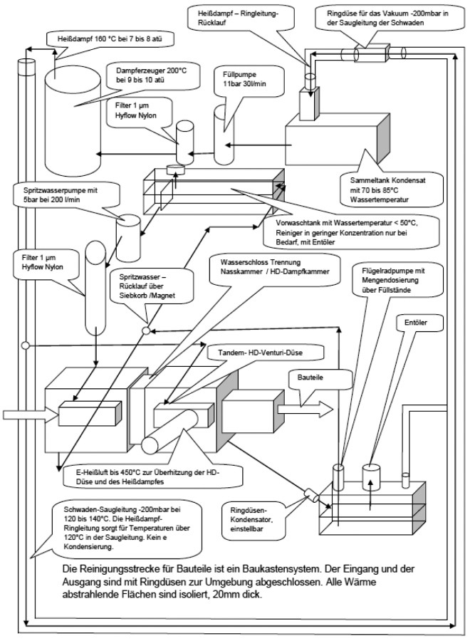 Fig 1: Design of a cleaning system using (all illustrations IBH)
Galvanic high-pressure steam cleaning is suitable for removing oil films and grease films up to a structure and layer thickness depending on the material of the contamination. Grease should be removed as thin films. Visible "grease layers", e.g. grease-lubricated ball bearings, cannot be cleaned with this technology as the dissolved grease particles cannot be sufficiently removed. Here, mechanical air flows must also be integrated into the process. The loosened dirt must be accurately extracted and processed.
Mechanical chips can be removed up to a certain weight and an appropriate flow area. The adhesion to the component surface is loosened in any case, the removal requires selected, additional mechanical flow systems.
In all possible applications, bath maintenance, water treatment and mechanical separation of solid particles in filters are possible. The separation filters should have a filtration fineness of at least 50 µm. The separation of dissolved dirt particles such as oils and greases as well as drawn soaps takes place in the steam generator. Regular desludging separates the dirt from the boiling water. The high-pressure cleaning steam is only contaminated with foreign particles, which can leave the steam generator with the steam from the boiling water after several reflections. The feed water is pressed through an absolute filter from Eaton, type Hyflow filter fineness 1 µm, at a pump pressure of 11 bar. A glass membrane (absolute particle size 40 µm) is also fitted in the filter housing to reduce the mechanical dirt ingress when refilling the steam generator. The feed water should have a bath temperature between 70 and 80 °C. The water hardness is always less than 5 °d(H). It will always be slightly to strongly acidic.
The steam generator output should be dimensioned according to the effective HP steam nozzle length. The nozzle slot width should always be 0.4 to 0.5 µm. This means that a steam generator output of 7 to 14 kW can be expected for a nozzle length of up to 180 mm, the length of the slot unwinding for round nozzles. Depending on the insulation quality and heat recovery. Electrical heating should be provided by sheathed heating cables. These are individually wired and individually controlled. The heating tapes are always run in continuous operation and switched in stages. The size of the steam generator can be increased in stages if required. If required, several smaller steam generators are safer for production. Flexible solutions are therefore possible in the event of a malfunction.
The annular gap between the surface to be cleaned and the outlet opening of the Venturi nozzle or the clear diameter of the nozzle should be between 1 and 5 mm wide. The contour of the component surface must be adapted to the clear nozzle contour. However, adequate results are also possible with round nozzle contours and rounded square box profiles.
Flat component surfaces must be cleaned with offset flat nozzles, as when plowing snow on the highway. The limit of performance is the dirt wave that forms. This must be removed from the component surface using sufficient mechanical energy, such as compressed air or a water jet.
The high-pressure steam nozzles are essential for the function. These are designed according to a calculation scheme. The ratios of the length dimensions are fixed and can be varied by zooming in on the size. The steam generator is always designed for 210 °C and 10 bar pressure. An additional 2 kW heater is required to superheat the steam at the tool nozzle.
The steam extraction system requires a vacuum of 50 to 200 mbar with a suction length of 8 m. The HP steam line as the supply line to the tool nozzles is a throttled open ring line that always provides dry, water-free steam. The ring line is located inside the steam pipe in order to heat it. The steam pipe is thermally insulated. The temperature of the outer wall should be lower than 50 °C.
The cleanliness of the cleaned component surfaces is up to < 200 µm metallic particle length with a width of up to < 40 µm and a thickness of up to < 30 µm.
Dimensioning of the HP steam ring line:
- clear cross-section 5 mm diameter, dimensionally stable up to 500 mbar negative pressure
- Temperature-resistant plastic up to 240 °C
- No water absorption
- No particle separation
- for pH < 5.
The opening of the ring line ends before the inlet to the vapor condensation collection tank with a full jet nozzle with a bore diameter of 0.6 mm designed as an injector nozzle to increase the negative pressure.
If required, the hall air must be filtered and fed into the cleaning chamber, air temperature 200 to 400 °C continuously with a pressure of approx. 50 mbar overpressure.
A water nozzle must be installed if there is a large amount of dirt. This flushes the dirt removed from the component surface into the collection tank and keeps the nozzle area free of dirt particles.
The galvanic voltage at the HP steam nozzle and/or the component is 2.5 to 3 volts DC at a current of less than 0.2 A.
The following cleaning systems are used in practice:
- 4 cleaning systems with ring nozzles of 40 mm and 80 mm clear diameter for closed V2A rectangular profiles for heat exchangers, external cleaning
- 1 cleaning system for window spacers, closed rectangular profile with perforation made of profiled aluminum
- 1 cleaning system for metal awnings, rods made of profiled V2A rectangular profile
- 1 cleaning system for sawn tubes cut to size from V2A
- 1 cleaning system in the final paint shop to remove localized oiling or oily traces of dirt before final painting, work in the paint shop
- 1 test cleaning system for wire cleaning of drawn welding wires
- 1 cleaning system for heat exchanger tubes made of V2A, diameter 20, thread rolled directly after rolling, outside and inside
Information on the specific production processes can be provided on request. The test documents are all internal company documents. Inspection is possible on request.
For the use of galvanic high-pressure steam technology, Figure 2 describes a scheme for the possible selection of this process as a cleaning technology.
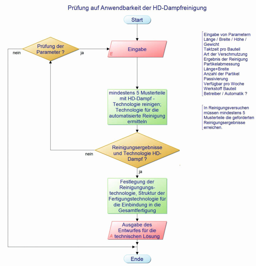 Fig. 2: Selection of the high-pressure steam cleaning process
The cleaning result per cleaning cycle will depend on the type and layer thickness of the soiling. Massive coatings should be pre-cleaned with an aqueous alkaline solution before high-pressure steam cleaning; flood injection rinsing is very effective here.
The solution is shown in Figure 3. The cleaning process is a sequence of technological processes that determine the cleaning result step by step. The tests for the following step must be carried out, otherwise the initial parameters for the subsequent step will not be available.
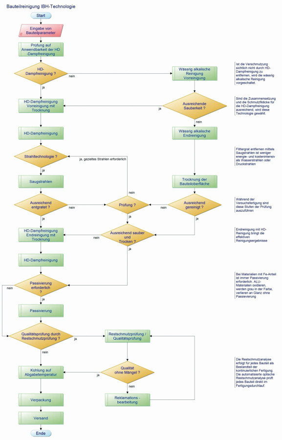 Fig. 3: Design of component cleaning using IBH technology
Figure 3 lists all the steps for component cleaning based on the results of this work. The dimensioning of the system, especially the tools, usually special nozzle systems, is carried out according to a selection system, which is shown in Figure 4.
The testing of the partial cleaning results must be automated so that consistent results are achieved. The test results are archived in the control system, i.e. assigned to the component number. Any faults that occur are clearly identified and can be called up.
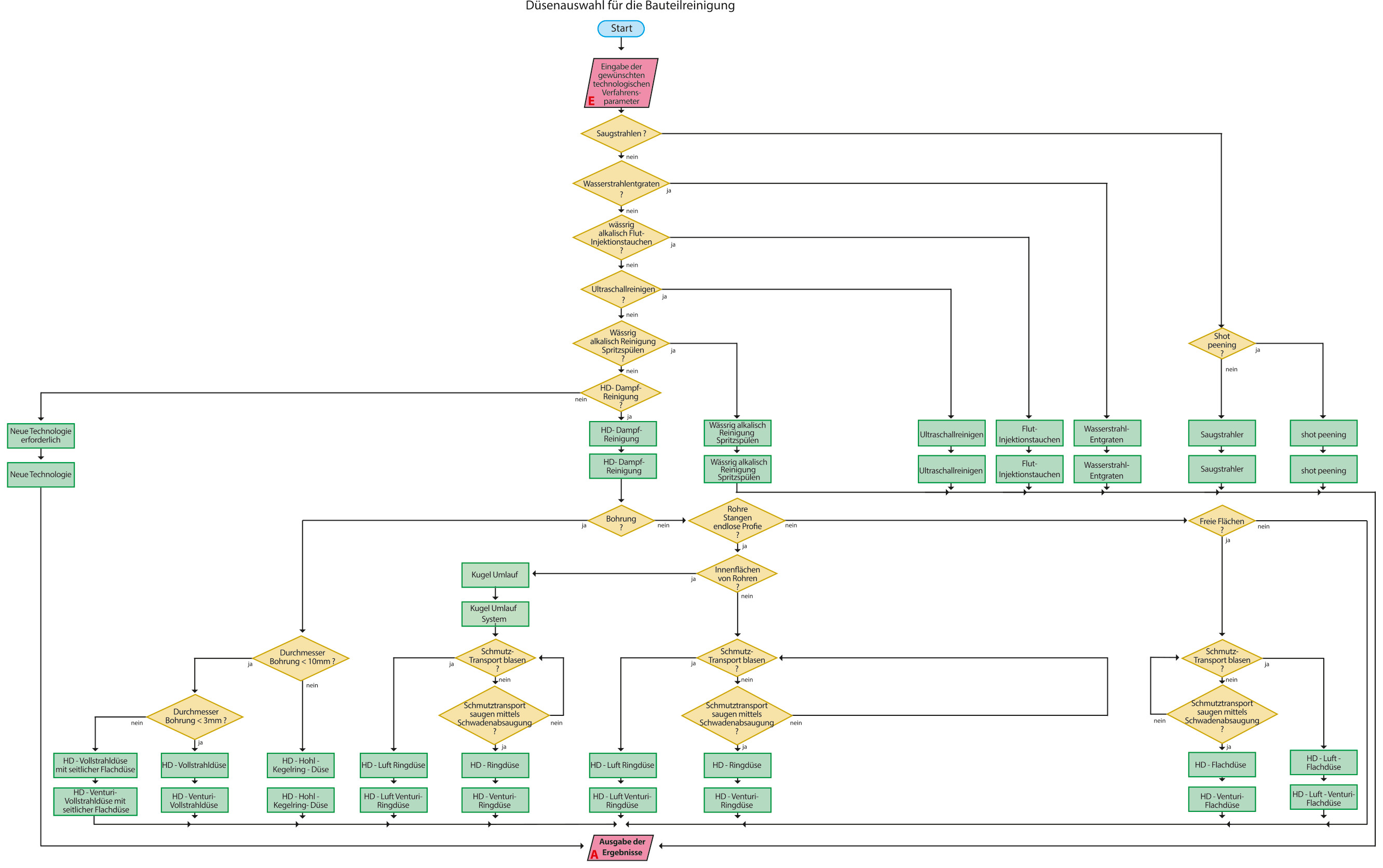 Fig. 4: Design and dimensioning of the tools for high-pressure steam IBH technology
The high-pressure steam rinsing process is used to achieve the final cleaning quality. The component surface is clean and dry. There are no chemical films on the component surface (Fig. 5).
As shown in Figure 3, passivation is added to the cleaning process if required. This step ensures clear, reproducible film formation on the component surface.
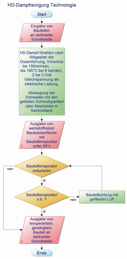 Fig. 5: Design of component cleaning with high-pressure steam IBH technology
Figure 6 shows an overview of the selection of possible technologies and their tools/nozzles. The design of the steam generator and the superheater system as well as the condensation of the vapors and their treatment in the water circuit of the system can be carried out on request.
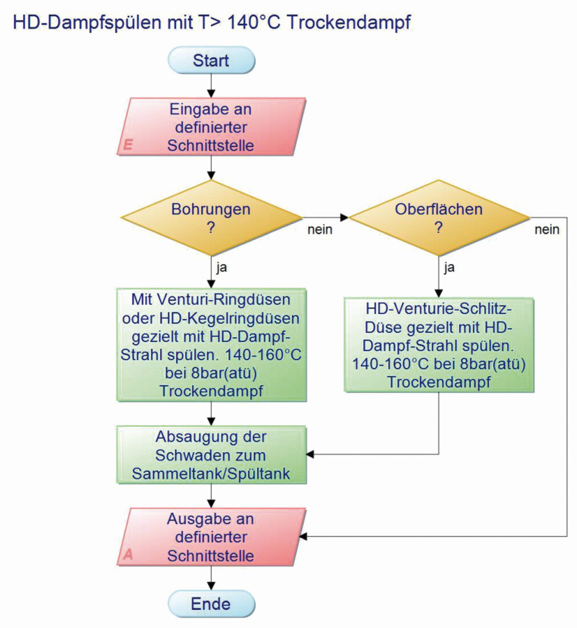 Fig. 6: Design of component flushing with HP steam IBH technology
The Venturi nozzles are dimensioned according to a calculation scheme in the evaluation of this work. Further information can be provided on request.
The parameters for the extraction and for the heating are also dimensioned in a calculation scheme in the evaluation of this work. Assistance can be provided on request.
Outlook
Based on the objective of this work, the results will enable the optimization of existing systems and the construction of new cleaning systems of a new quality. The solutions implemented show that energy and media savings are possible.
As part of the evaluation of this work, investigations into the automated deburring of cut edges in control blocks are underway. Up to now, sandblasting and high-pressure water jet systems have been used here. Suction jet deburring can be used in combination with high-pressure steam cleaning. Energy savings from the current 40 to 110 kW pump power to less than 30 kW electrical power will be possible in future with optimized results. The media circuits are closed and therefore have a much smaller media volume. The continuous treatment of the media and the closed heat circuit are the basis for innovative cleaning systems.
The use of chemical additives such as aqueous cleaners can be greatly reduced or even eliminated. The cleaned component surface after high-pressure steam cleaning always ends with a component surface without a film of residual particles from the cleaning process. This means that the cleaned component surface can be reliably sealed as required.
The steam generator developed enables the heating to be designed in stages. The results of this work therefore make a modular system for cleaning systems possible. Only by varying the number and size of the tools can component surfaces of different sizes and shapes be cleaned.
Figure 3 refers to the quality inspection of the cleaning process. A research project is currently underway with the aim of using robots to guide the tools and carrying out non-destructive optical inspection by camera as a residual dirt analysis on each component, integrated into the automatic cleaning process.
The results of this work open up new avenues in the surface cleaning of components.
Test results of current cleaning systems with high-pressure steam technology and with wet chemical cleaning of components from the same series production - ABS servo control blocks made of aluminum - have shown by the lengths and the number of metallic particles found on the test filters that the high-pressure steam technology cleans the components cleaner - with less media consumption and lower energy consumption - than wet chemical cleaning.
HD steam parameters:
7 kWh for the steam generator + 2 kWh for superheating; < 3 liters/h fresh water
Wet chemical cleaning parameters:
30 kWh for heating and pumps + chem. Cleaner additive; > 50 liters/h fresh water
Literature
TRW - Test documents, October 2014, available for inspection on request


