
Part 5 of the cleaning series presents experiments on surface cleaning using saturated steam. The dry steam cleaning system, which gives this series of articles its name, is used for the first time.
Tests using saturated steam as a medium for cleaning surfaces
Flowing superheated steam as a medium for cleaning an object surface generates discharges and charges between the object surface and the foreign particles due to its positive charge. With its mechanical flow energy and electrical charge, the steam moves the foreign particles from the surface. The size of the charge increases with the steam temperature and the steam speed. The distance and the nozzle contours influence the effective temperature on the surface and vary the mechanical energy for moving the foreign particles. The charge of the flowing steam changes from negatively charged directly in the nozzle outlet cross-section to positively charged at a distance of 20-50 mm. Steam can also be electrically charged. Different cleaning results are demonstrated depending on the parameters.
Steam generation in open and closed steam generators begins with water heating. The volume of water expands as it heats up. In the test facility, there are 30 liters of water in the steam generator. These 30 liters expand to a volume of 31.302 liters at 100 °C. Thus, the 30 liters of water expand to a volume of 31.8 liters of water at a water temperature of 120 °C (author's collective, Handbuch für Kesselwärter Band 1, Tabelle 2, VEB Deutscher Verlag für Grundstoffindustrie, Leipzig, 1960).
The resulting overpressure, measured in atü, delays the evaporation of the water. At 6 atü, the water boils at 164 °C, i.e. the volume of water increases from 30 liters at room temperature to 32.55 liters. These values are essential for checking the water level in the steam generator for functional safety.
The increasing temperature changes the steam volume. With saturated steam and superheated steam, the volume per kg of steam becomes smaller as the pressure increases. With superheated steam, the volume per kg of steam increases with increasing temperature and constant pressure. In the test series, the system was run up to the parameters and then operated with a constant nozzle opening over the test period, i.e. with constant pressure in the steam generator.
At 9 atü, 1 kg of steam has a heat of vaporization of 481.8 kcal/kg (Autorenkollektiv, Handbuch für Kesselwärter Band 1, Tabelle 9, VEB Deutscher Verlag für Grundstoffindustrie, Leipzig, 1960).
The volume of 1 kg of saturated steam at 9 atü has a volume of 0.198m3/kg (Autorenkollektiv, Handbuch für Kesselwärter Band 1, Tabelle 10, VEB Deutscher Verlag für Grundstoffindustrie, Leipzig, 1960).
 – spezifische Entropie (S): T-S-Diagramm für Wasser beim Betrieb einer Turbine") Fig. 1: Temperature (T) - specific entropy (S): T-S diagram for water during operation of a turbineTheseparameters were observed in all tests. It is known from the literature for boiler operators that superheated steam occupies a larger space than saturated steam with the same amount of water in the steam generator and the same heat content. This reduces the water flow rate and thus the energy requirement in the running process. The steam saving is 1 % per 6 ° K overheating.
Fig. 1: Temperature (T) - specific entropy (S): T-S diagram for water during operation of a turbineTheseparameters were observed in all tests. It is known from the literature for boiler operators that superheated steam occupies a larger space than saturated steam with the same amount of water in the steam generator and the same heat content. This reduces the water flow rate and thus the energy requirement in the running process. The steam saving is 1 % per 6 ° K overheating.
The following technology is used in the experiments in this work:
200 °C hot saturated steam is superheated to 300 °C. There is therefore a temperature difference of 100 °C, which means that 16.7 % steam is saved.
The superheating takes place by means of a hot air nozzle (2 kW heating power) by blowing on the hot steam nozzle in the intake area of the ambient air of the nozzle at approx. 300 to 350 °C air and hot nozzle temperature. The hot nozzle steam mixed with air is then always hotter than 250 °C. This mixture of hot steam and hot air is used in all experiments.
The selected parameters significantly reduce the energy losses of the steam line. This mixture cools the component surface to be cleaned, i.e. an additional negative pressure is created at the point of impact. This draws in ambient air. This negative pressure is used in the process to extract the resulting vapors. The steam lines are installed as a ring line in the return line of the vapors to heat the vapors. This creates an almost closed media circuit between the steam generator, superheated steam nozzle, component, vapor extraction, condensation, collection tank for filling the steam generator, filtration/separation and refilling the steam generator.
The transition conditions between liquid water and steam are shown in the boiling point curve of the state diagram (Fig. 1).
Depending on the reference level, the following units were derived from the technical atmosphere:
- absolute pressure (reference level: 0): ata (pa)
- Pressure in at above the reference level: atü (pü)
- Pressure in at below the reference level: atu (pu)
- the technical atmosphere was standardized as the amount of pressure that causes 10 m water column
- 1 at = 10 mWS = 1 kp/cm2 = 9.80665 N/cm2 = 0.980665 bar = 98,066.5 Pa
- 1 Pa = 1.0197 x 10⁻⁵ at or 98.0665 kPa = 98066.5 kg/ms2 = 1 at.
"Technical atmosphere at" from Wikipedia entry on the Internet.
When water evaporates in a colder environment with the addition of heat, parts of the gaseous water condense back into very fine droplets. The water vapor then consists of these droplets and gaseous, invisible water. This mixture is known as wet steam, which is visible when boiling water, for example. In Figure 1, the range of wet steam extends to the critical point at 374 °C and 221.2 bar.
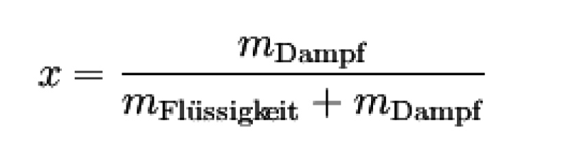
The content of wet steam in liquid water is characterized by the mass fraction x, which can be calculated using the following formula:
Equation 1:
Above this temperature, water vapor and liquid water can no longer be distinguished from each other in terms of their density, which is why this state is referred to as "supercritical". Supercritical water has particularly aggressive chemical properties. Below the critical point, the water vapor is therefore "subcritical", whereby it is in equilibrium with the liquid water.
If it is heated further in this area after the liquid has completely evaporated above the associated evaporation temperature, "superheated steam" or "superheated steam" is produced. This form of vapor no longer contains any water droplets and is a gas in its physical behavior and not visible to the eye.
"Saturated steam" lies in the border area between wet steam and superheated steam. In the literature, "saturated steam" is also referred to as "dry steam".
Equation 2: x = 0 and x = 1
The two boundary curves x = 0 and x = 1 in Figure 1, which meet at the critical point, are of particular importance: The curve x = 0 delimits the area of liquid from wet steam, while the curve x =1 separates wet steam from superheated steam and at the same time marks the state of saturated steam. Other designations for the curve x = 0 are the boiling line or lower limit line, the curve x = 1 is also called the tau line, saturated steam curve or upper limit line. The notation with x for the mass fraction is not uniformly defined here, as the mass fraction is specified with w, particularly in chemistry, and x here mostly stands for the mass fraction. Since both quantities can be converted into each other and are equal in the limit values 0 and 1, this plays a subordinate role.
A useful rule of thumb for calculating the saturated steam temperature from the saturated steam pressure and vice versa is
Equation 3:
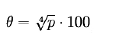
..., if you enter the pressure p in bar (absolute). The corresponding temperature θ is given in degrees Celsius; this formula is valid in the range pkr. > p > p = 3 bar (200 °C > θ > 100 °C) to an accuracy of about 3 % (see: Chemie.de/lexikon).
Steam - water - steam, interplay in the balance of forces
If the number of molecules from the liquid over the surface is free of water vapor, the water evaporates into the free gaseous space. Depending on the structure of the space, open space or closed space, excess pressure builds up as the degree of filling increases.
If the pressure remains constant, adding more heat will not cause the temperature to rise further. Instead, the water will turn into saturated steam. The temperature of boiling water and saturated steam within the same system is the same, but the heat energy per unit mass is much greater than that of steam in open space.
At atmospheric pressure 1 ata, the saturation temperature is 100 °C. However, if the pressure is increased, this allows the addition of more heat and an increase in temperature without a change in phase.
Therefore, increasing the pressure is effective for both the enthalpy of water and the saturation temperature. The relationship between the saturation temperature and the pressure is known as the vapor saturation temperature curve (Fig. 2).
") Fig. 2: Steam saturation curve (0 atü corresponds to 1 ata = 1 bar atmospheric pressure)
Fig. 2: Steam saturation curve (0 atü corresponds to 1 ata = 1 bar atmospheric pressure)
Water and steam can coexist at any pressure on this saturation temperature curve. Steam at a state above the saturation curve is called superheated steam.
- Temperature above saturation temperature is called the degree of superheat of the steam.
- Water in a state below the curve is called sub-saturated water.
If the steam can escape from the boiler at the same rate as it was produced, the addition of further heat simply results in an increase in the rate of steam production. If the steam does not leave the boiler and the heat supply is maintained, the energy in the boiler becomes greater than the energy leaving the boiler. This excess energy increases the pressure, which in turn allows the saturation temperature to rise, as the temperature of the saturated steam correlates with its pressure in the confined space. The heat input into the steam generator system is monitored and controlled by temperature measurement and/or pressure measurement.
The cleaning process using superheated steam (HP steam) as part of production is considered a necessary production step to achieve the desired component surfaces.
A new type of steam generator is developed as a prerequisite for this work. The findings of previous solutions are compiled. The new development resulted from optimizations of previous solutions and new geometries. The space and flow conditions in the steam generator are re-dimensioned.
The following historically important solutions are incorporated into the development. The circulation of the water medium in the developed steam generator is essential for optimum steam generation.
The test system (Fig. p. 889) produces HP steam for 1 slotted nozzle with a length of 180 mm or HP steam for 2 ring venturi nozzles with a clear diameter of 30 mm each and a slot width of 0.05 mm. Furthermore, the system generates no free vapors outside the cleaning system and small, negligible vapors on the contact surface of the HP nozzle to the component surface. The operating temperature of 200 °C is reached after 20 minutes at a starting temperature of 20 °C. During operation, the feed water from the storage tank is heated from 80-200 °C in the electrically heated steam generator. A small amount of fresh water, 0.5 to 1 liter of 10 °C cold fresh water per hour, is added to the feed water with a tank volume of 400 liters. The pump for refilling the steam generator with feed water generates heat in the feed water due to the pressure and friction and heats it additionally. The Venturi nozzle X, operated with compressed air, sucks the vapors out of the system and tool areas. The flow through the Venturi nozzle condenses the vapors to an adjustable 60 °C to 80 °C. The condensate drips into the feed water. The condensate drips into the feed water tank. This process charges the water in the feed water tank electrically. The piping in the extraction area is insulated, i.e. the HP steam supply line for the tool nozzle on the component surface is routed as a ring line within the insulated vapor extraction system. This ensures that the vapors are transported safely to the condensation nozzle, where the temperature difference is sufficient to condense the vapors.
This minimizes the heat loss Q from the vapour transport, the residual heat of the condensate is fed to the fresh water. In the tests, work is carried out in closed, heated rooms with room temperatures B of 16-22 °C. The small room temperature fluctuations are neglected as an influencing factor in the energy balance. A value of 20 °C room temperature B is assumed in the observations.
The electric heater A with several heating cartridges, individually controlled, generates a maximum heating output of 24 kW. This only occurs during the heating-up phase when the system is started. When the operating temperature of 200 °C is reached in the steam generator, the output of heater A drops to 7-12 kW. If the system is used continuously, the lower value applies, as the waste heat heats up the feed water. The efficiency losses D are stated below in the text. The electric heating cartridges have a high efficiency due to insulated installation and maximum heat conduction between the heating wire and the heating pipe filled with flowing water as well as circulation due to the heat difference in the heating pipe.
In the test system, the HP steam pipes and fittings were not insulated. The expenditure would have been inappropriate for the operation of the system. The heat losses of the steam pipe in the test plant are set at a flat rate of less than 3 % of the heating capacity A.
The live steam heat E is released at the highest point in the vertically positioned insulated steam generator into the HP steam pipe as useful steam to the HP nozzle. The HP steam line is located as a ring line in the insulated steam extraction line, i.e. it is largely insulated from the room. Special materials such as glass fibers are used.
The mechanical losses G in the pumps and valves are valued at less than 5 % in the energy balance and can therefore be neglected for the test series.
The contact surfaces of the heated components of the system are directly connected mechanically, usually with screws. Here the direct heat transfer H takes place as contact heat into the frame, housing etc. This energy is valued at less than 3 % of the heating energy A and is therefore not examined further for the energy balance.
The hose lines K outside the housing of the test system are insulated, have an outer diameter of 70 mm and are 40-50 °C warm. Depending on the length of the hose lines, energy losses occur here due to room heating. These values were not determined, as the loss was compensated for by higher electrical heating power at a maximum hose length of 12 meters. The test temperatures were always comparable, i.e. this amount of energy was constant and therefore had no effect on the test result.
The actuator units L in the test system were small in size and number, i.e. less than 1 % of the heating A in relation to the energy requirement.
The exhaust steam heat N was largely absorbed by the vapor extraction system. The exhaust steam heat values were unchanged in all tests, i.e. they had no influence on the test results.
The system vapors from the collector U and the extracted vapors from the component surface V are completely included in the vapor extraction W.
The vapor extraction unit X is equipped with a Venturi nozzle NW 40 and operates using compressed air at 6 bar with an annular gap of 6.28 mm2 nozzle opening.
The electric post-heater T with adjustable power between 0.5-2 kW is essential for optimum effect on the tool. The post-heater is a fan heater that heats room air and feeds it into the HP nozzle as supply air. This heats the HP nozzle body to 300-400 °C, and the room air drawn in and fed into the Venturi HP nozzle is mixed with the dry steam.
This creates a temperature-controlled high-pressure steam flow on the surface of the component at speeds in the Mach 1 range, i.e. the speed of sound. The mixed hall air performs mechanical work and transports the loosened dirt particles.
Literature
[1] Kalide, W.; Sigloch, H.: Energieumwandlung in Kraft - und Arbeitsmaschinen, Carl Hanser Fachbuchverlag, 10th edition, 2010
Schach, W.: Umlenkung eines Flüssigkeitsstrahles an einer ebenen Platte, Springer, Berlin, 1934 Reich, F.: Umlenkung eines freien Flüssigkeitsstrahles an einer senkrecht zur Strömungsrichtung stehende ebenen Platte, VDI-Verlag, Berlin, 1926
