
Current environmental and energy policy calls for material and energy recycling. In workpiece drying, this can be achieved by means of circulating air and condensation drying. The principles and dimensioning of the two processes are described. The h,x diagram facilitates their calculation. The flow distribution plays an important role for the workpieces as bodies around which the air flows.
 The basic principles and fundamental formulas of drying are described in [1, 2].
Modern surface technology requires relatively short drying times. This means that the drying potential of the air must be high until the end of the process. As a result, high energy losses are inherent in the simple drying process. The first step in minimizing these losses is air circulation drying. The exhaust air contains the large amount of energy from the evaporated water. In addition to improved economic efficiency, recovering this energy has environmental benefits in the form of a reduced contribution to global warming. Energy and solvents can be recovered from the exhaust air using condensation drying. These two drying processes will be the subject of this article. The main difference between the processes is the type of air flow (Fig. 1).
The water introduced with the goods is removed again with the respective air flow in the simple and recirculation dryers. It is removed from the circulating air dryer with the low exhaust air flow. In the condensation dryer, on the other hand, it is discharged in liquid form.
In the supply air dryer, the entire air flow is also the exhaust air flow. This means that the entire energy content is also waste heat. In the recirculation dryer, the majority of the exhaust air is recirculated. Only a small proportion is discharged with the water as exhaust air. Despite this, the heat loss is still high. Although the proportion through the air is significantly reduced, the total enthalpy of vaporization of the water, which accounts for the greater amount of energy, is still included. The condensation dryer with heat pump is much more economical. In this case, the entire exhaust air is recirculated and the enthalpy of vaporization is also recovered. Only the heat content corresponding to the temperature of the water is released. However, the condensate separator must be installed as additional technology.
Circulating air dryer
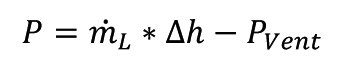
In the recirculation dryer (Fig. 2), one or more fans drive the air in a circle through the drying chamber, the recirculation duct and the distribution grid. The pressure loss in the recirculation dryer is slightly higher than in the simple dryer due to the recirculation channel. The fan energy does not need to be added to the calculation, as fans are also required to accelerate the air in the simple dryer. The entire mechanical powerPVent, which is sent on its way with the fan, is converted into internal energy of the air and can be saved accordingly in the heating power P:

The situation is different with the efficiency of the fan. This lost energy is converted into heat in the fan components.
The comparatively weak supply air flow mixes with the recirculated air flow and then passes over the goods. An exhaust air flow is then separated, the volume flow of which corresponds to the supply air flow. This exhaust air flow carries the vapor of the evaporated water film with it.
Air conditions and calculation variables for the circulating air dryer are shown in Table 1.
| No. | Air condition | Air mass | Vapor pressure | Saturation vapor pressure |
Relative humidity |
Enthalpy |
| 1 | Fresh air |
mL,1 |
ρD,1 |
ρS,1 |
φ1 |
h1+x,1 |
| 0 | Drying air |
mL,0 |
ρD,0 |
ρS,0 |
φ0 |
h1+x,0 |
| 2 | Exhaust air |
mL,2 |
ρD,2 |
ρS,2 |
φ2 |
h1+x,2 |
| 3 |
Recirculated air |
mL,3 |
ρD,3 |
ρS,3 |
φ3 |
h1+x,3 |
Compared to the simple dryer [1], the following changes result (Fig. 3).
 Fig. 3: Principle of the recirculating air dryer
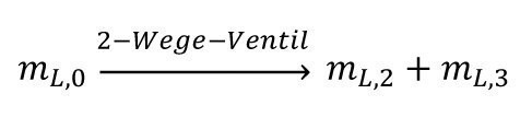
The recirculated air flow is branched off from the exhaust air:
resp.
and
The drying air flow therefore corresponds on the one hand to the sum of the recirculation air flow and the exhaust air flow and on the other hand to the sum of the recirculation air flow and the supply air flow.
The larger proportion of the drying air is returned to the inlet.
The fan not shown in Figure 3 is of course included in the energy balance with its energy

QW is the energy discharged with the goods and QVent is the mechanical energy of the fan.
The statement "without additional energy" is therefore not correct for convection dryers. "Without additional heating energy" would be correct. Regardless of this, the heating coil is required at least for start-up.
The supply air (state 1) mixes with the circulating air (state 3). This produces the drying air mixture (state 0). A fan drives the mixture through the heating coil (calorifier) and the diffuser into the drying chamber. The drying air absorbs (all) the water adhering to the fabric.
This produces the exhaust air (state 2), a large part of which is branched off as recirculated air (state 3) for heat recovery. The fan simultaneously mixes the two streams (states 1 and 3).
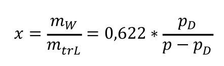
During heating in the heating coil, the ratio of water vapor to air remains constant. The absolute humidity ([1]; Table 9, Eq. <5>) in kg water/kg dry air remains constant, but the relative humidity decreases sharply,
which greatly increases the drying potential.
The absolute humidity forms with the maximum possible humidity fmax, i.e. the
solubility of water vapor in the air as a function of temperature, forms the relative humidity, which is often expressed as a percentage.
The wet bulb temperature changes only slightly with the relative
humidity (Fig. 4); about 2 degrees per 10 percent.
 Fig. 4: Wet bulb temperatures
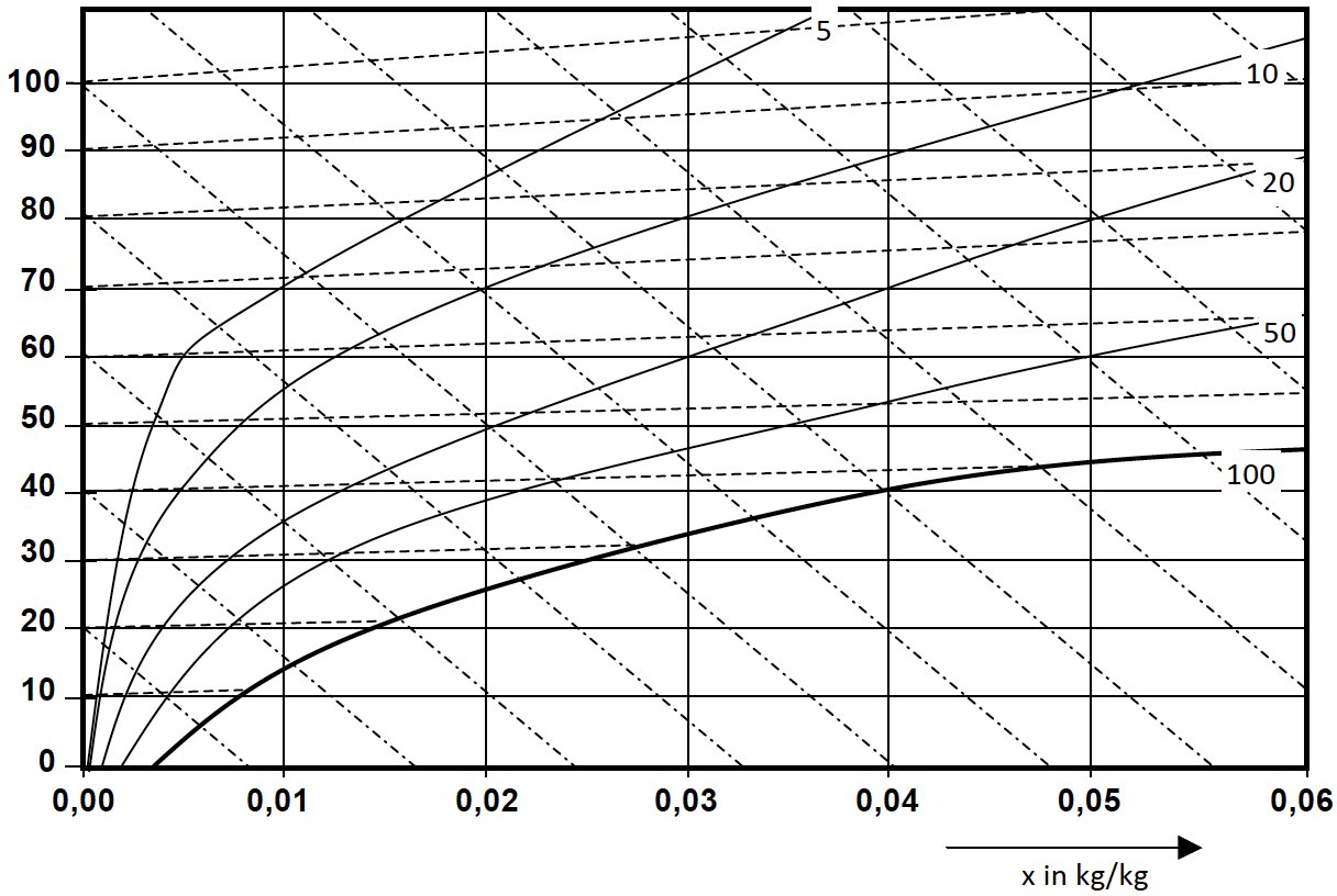 Fig. 5: Template h,x diagram
The fact that the composition of the air in the heating coil remains constant leads to a pure increase in enthalpy, i.e. to a vertical line in the h,x diagram (Fig. 5). With purely convective drying of the goods, the downward line then follows the corresponding isenthalpe (line of equal enthalpy), because the heat of the air is transferred to the water film as evaporation energy.
Air flow
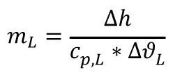
With an enthalpy of vaporization r = 2458 kJ/kg of water and cp,L = 1.01 kJ/(kg*K), the necessary mass of air per kg of vaporized water follows:
With Δh = r and ΔϑL = 18 °C, this results in, for example:
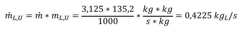
135.2 kg is therefore required for these conditions
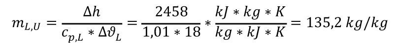
of recirculated air to remove 1 kg of water at a time.
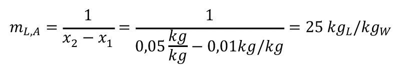
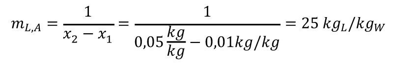
The fresh air has an absolute humidity of x1. The discharged air has a humidity of x2. The required air mass (per kg of water) for its removal is the same, e.g. x1 = 0.01 kg/kg and x2 = 0.05 kg/kg is obtained for
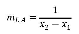
the discharge or clean air quantity
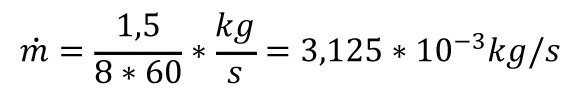
For an entrained water quantity of 1.5 kg in 8 min,
i.e. for a flow of
the resulting recirculated air flow required is
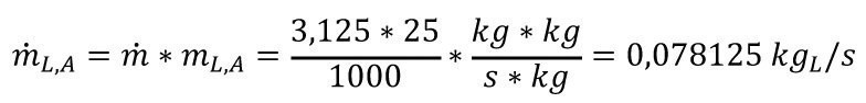
and for the exhaust air flow
As the temperatures and therefore the densities are different,
must be taken into account accordingly for the volume flows.
h,x diagram
The air conditions and their changes can be described with the help of the gas laws. However, as we are "eye animals", pictorial representations are more meaningful for us. We have also learned to read further information from graphical representations. The h,x diagram(Fig. 5, formerly Mollier diagram) is a good tool for describing air conditions.
The ordinate has no unit of measurement because cp,L ≈ 1 kJ/(kg*K), i.e. in the numerical value h ≈ ϑ . h in kJ/kg and ϑ in °C. Parameter: rel. humidity in percent.
Figure 6 shows a diagram with plotted values for a dryer.
 Fig. 6: Mollier diagram with example drying process drawn in
A simplified representation of the drying process in the h,x diagram is shown in Figure 7.
 Fig. 7: Basic drying process; h,x diagram
The process (Fig. 7) starts at the initial temperature of the air and its absolute humidity (ϑ1;x1). During heating, the humidity does not change; only the temperature and enthalpy content increase (ϑ0; x0 = x1). In the diagram, the trace runs vertically upwards (red arrow).
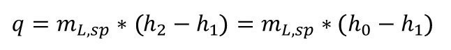
During evaporation, the enthalpy content remains constant (h2 = h0); only the form of the heat changes. The air temperature becomes the heat of evaporation of the absorbed vapor. The air cools down accordingly along a line of constant enthalpy (blue arrow).
In a simple supply air dryer, the next batch starts again at the initial values of the fresh air.
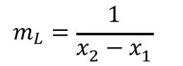
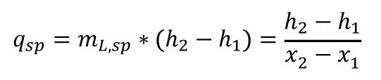
The specific air mass, i.e. related to the evaporation of 1 kg of water, is again derived from the final and initial humidities.
These values can be easily taken from the h,x diagram
diagram.
The specific heat requirement for the preheater is then calculated as follows:
This can be seen more precisely in the heat balance (Tab. 2).
| Heat supplied | heat dissipated |
|
Air and the moisture it contains |
Exhaust air and the moisture it contains |
|
Heat content of goods |
Heat content of dry goods |
|
Heat content of water film |
(heat content of steam) |
|
Heat content of racks |
Heat content of racks after drying |
|
Ambient heat loss |
The start of the recirculation dryer is the same (Fig. 8). However, the air from state 2 is then recirculated and mixes with air from state 1 to state 0.
The state diagram of the recirculation dryer, i.e. the dryer with exhaust air recirculation, is shown in Fig. 8. The process starts on the left of the diagram at the level of humidity (x1) of the outside air. During the process, it shifts to the moisture content of the mixed air (x0). In any case, the air is heated up to the enthalpy h2. The length ratio of the recirculation and supply air arrows corresponds to their mass ratio. As can be seen from the length of the heating arrows, the heat requirement decreases significantly with the transition to recirculation mode. A further advantage is the lower overall temperature, which leads to a reduction in heat losses to the environment.
 Fig. 8: Principle diagram of the recirculating air dryer
The mixed air data always lies on the straight line connecting the output air volume data (see also Fig. 8). The connecting line between the data of the drying end point and the data of the fresh air is characterized by the different air masses. The length of the green arrow corresponds to the proportion of fresh air; the length of the purple arrow corresponds to the proportion of exhaust air (recirculated air). The air requirement for the recirculation dryer is greater than for the simple supply air dryer. This is because
is.
The specific heat requirement for the heater of the simple dryer is the same
The following applies accordingly for the recirculation dryer
From the similarity of the triangles in the diagram follows

As you can see, the statement is correct: with the same exhaust air values, the temperature is significantly lower compared to the supply air dryer. This not only reduces the required heat output, but also significantly reduces the ambient losses. A significant proportion of the heat output is supplied by the fans.
 Fig. 9: h,x diagram for a recirculating air dryer with example values Fresh air: 20 °C; x = 0.005 kg/kg; ps = 2338 Pa; φ = 33 %; xs = 0.015 kg/kg; h1+x = 32 kJ/kg Exhaust air: 32 °C; x = 0.0242 kg/kg; ps = 4758 Pa; φ= 98 %; xs = 0.025 kg/kg; h1+x = 92 kJ/kg
The fresh air has an absolute humidity of x1. The discharged air has a humidity of x2. The required air mass (per kg of water) for water absorption is equal to
z. e.g. with x1 = 0.01 kg/kg and x2 = 0.05 kg/kg, the following is obtained for the exhaust or clean air quantity
For the above example
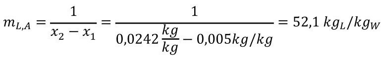
In this case, 52.1 kg of air is required to evaporate 1 kg of water.
![Abb. 10: Verlauf des Luftzustandes beim einfachen Trockner (Zulufttrockner; Bereich I) und beim Umlufttrockner (Bereich II) bei gleicher Trockenlufttemperatur. In Anlehnung an [3]](/images/stories/Abo-2020-11/thumbnails/thumbnails/thumbnails/thumbnails/thumbnails/thumbnails/gt-2020-11-0171.jpg "Abb. 10: Verlauf des Luftzustandes beim einfachen Trockner (Zulufttrockner; Bereich I) und beim Umlufttrockner (Bereich II) bei gleicher Trockenlufttemperatur. In Anlehnung an [3]") Fig. 10: Progression of the air condition in the simple dryer (supply air dryer; area I) and in the circulating air dryer (area II) at the same dry air temperature. Based on [3]
Fig. 10: Progression of the air condition in the simple dryer (supply air dryer; area I) and in the circulating air dryer (area II) at the same dry air temperature. Based on [3]
| Supply air dryer | Recirculating air dryer | |
| Start |
KZ-1 2800 |
KU-3 2250 |
| end | 250 | 500 |
| Log. Average | 1056 | 1164 |
A different picture emerges if the circulating air dryer is heated to the same temperature as the supply air dryer (Fig. 10). As a result, the enthalpy at which drying takes place is significantly higher.
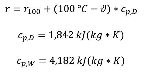
With the formula
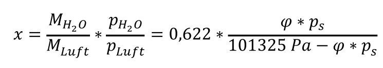
or
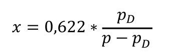
the moisture contents and their differences can be easily converted into partial pressures or partial pressure differences (lower part of the diagram in Fig. 10).
Δp changes less with the circulating air dryer; drying along the product is more uniform. However, as the mean logarithmic vapor pressure difference is greater, the product dries faster. In addition, the drying speed is increased by the generally higher air speed compared to the supply air dryer. If the air flow in the example is allowed to cool down by 20 °C (Fig. 10), thereby releasing r = Δh =2458 kJ/kg to the water film, the carrier for this energy is
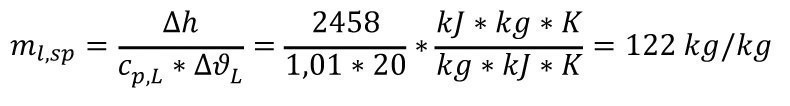
Recirculated air is required.
The fresh air enters with 0.011 kg/kg humidity. At the outlet, it has 0.05 kg/kg, i.e. a difference of x = 0.039. The fresh air requirement for this case is therefore
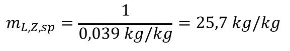
The ratio of fresh air to recirculated air is 1 : 4.75, i.e. the proportion of fresh air is only 21 %.
The steam generated from the rinsing film must be continuously removed, otherwise it would increasingly disrupt the drying process and eventually interrupt it completely. For this reason, fresh air must always be supplied in the quantity that removes the steam as exhaust air. The other option for getting rid of the steam is to freeze it out of the drying air or to absorb it, whereby the latter option is irrelevant for surface technology.
Further water vapor is present in the fresh air [1]. Its influence is greatest in the supply air dryer. If the majority of the air is recirculated, the influence is of course significantly reduced. It is completely suppressed in the case of complete recirculation, i.e. in a condensation dryer.
Condensation dryer
In a condensation dryer (Fig. 11), the exhaust air must be cooled down to the mist range.
The dashed line in Figure 11 shows the boundary between the cooling area (below) and the drying area (above). During condensation cooling, the evaporation heat of the adhering rinsing water is also recovered. It may therefore be practical to avoid additional heating. How can this be? The fans for circulating the recirculated air require several kW of power. This power is converted into heat via the movement. It may be sufficient to compensate for the losses.
 Fig. 11: Principle of condensation drying
  Fig. 11: Principle of condensation drying
Of course, it is not necessary to cool down as far as shown in Fig. 11, i.e. to the moisture content of the fresh air, although the same conclusions apply as for the recirculation dryer (Fig. 12).
In contrast to the circulation dryer, the condensation dryer also has a cold trap which removes the water carried in with the goods. Such a cold trap is of course designed as or in conjunction with a heat exchanger.
The values in Table 4 should apply to the condensation dryer.
| No. | Air condition | Air mass | Vapor pressure | Saturation vapor pressure |
Relative humidity |
Enthalpy |
| 1 | Fresh air |
mL,1 |
ρD,1 |
ρS,1 |
φ1 |
h1+x,1 |
| 0 | Drying air |
mL,0 |
ρD,0 |
ρS,0 |
φ0 |
h1+x,0 |
| 2 | Exhaust air |
mL,2 |
ρD,2 |
ρS,2 |
φ2 |
h1+x,2 |
| 3 |
Recirculated air |
mL,3 |
ρD,3 |
ρS,3 |
φ3 |
h1+x,3 |
| 4 | cooled circulating air |
mL,4 |
ρD,4 |
ρS,4 |
φ4 |
h1+x,4 |
Compared to the simple circulating air dryer [1], the following changes occur:
The cooled and reheated circulating air that is fed to the dryer has the same mass mL,4 = mL,3, but different values for vapor pressure, saturation vapor pressure and relative humidity (Fig. 13).
The air mass is not changed in the cold trap, i.e. mL,4 = mL,3; only the water mass. The following applies in continuous operation
The cold trap often consists of a heat exchanger and a heat pump. A heat exchanger works without additional energy.
The heat pump has its own coolant circuit (Fig. 14).
Together with the cold trap and the heater, this results in the air circuit (Fig. 15).
 Fig. 14: Heat pump coolant circuit; the designations refer to the coolant, not the dry air
 Fig. 15: Dryer with air circuit
In the heat exchanger, the exhaust air is "pre-cooled" with the air from the heat pump. In the cold part of the heat pump (coolant evaporator), it is cooled down to the mist range in order to separate out the water absorbed in the dryer. It is then reheated in the warm part of the heat pump (coolant condenser). Heating then continues in the heat exchanger in counterflow with the exhaust air. It is then driven through the heater via the fan not shown in Figure 15 , where it is finally brought back to the required enthalpy of the drying air.
Figures 16 and 17 show industrial versions of condensation dryers and cold traps respectively.
![Abb. 16: Airgenex® Entfeuchtungstechnologie [5] 1. Schnittstelle Airgenex® Entfeuchtungstechnologie/Trockner: Feuchte Luft wird aus dem Trockenraum ab- und der Luftentfeuchtung zugeführt 2. Der Vorkühler, der gleichzeitig als Vorerhitzer dient (4) und energielos arbeitet, ist optional einsetzbar. Seine Wirtschaftlichkeit ist von der gewünschten Trocknungstemperatur abhängig 3. Die Feuchtigkeit schlägt sich an den Lamellen des Luftkühlers nieder und läuft über die Ablaufwanne und den Kondensatablauf aus der Trocknungsanlage 4. Die abgekühlte, entfeuchtete Luft wird mittels optional einsetzbarem Vorerhitzer (2) energielos aufgewärmt 5. Der Lufterhitzer erwärmt die Luft auf die geforderte Prozesstemperatur 6. Der Prozessluftventilator sorgt für den notwendigen Luftaustausch zwischen Airgenex® Entfeuchtungstechnologie und Trockenraum 7. Jetzt wird die trockene, ungesättigte Luft in den Trockenraum geführt und nimmt dort die Feuchte des Produkts auf Somit ist der Kreislauf geschlossen](/images/stories/Abo-2020-11/thumbnails/thumbnails/thumbnails/thumbnails/thumbnails/thumbnails/thumbnails/thumbnails/thumbnails/thumbnails/thumbnails/2020_11_Trocknen_Abb_16gt-2020-11-0169.jpg "Abb. 16: Airgenex® Entfeuchtungstechnologie [5] 1. Schnittstelle Airgenex® Entfeuchtungstechnologie/Trockner: Feuchte Luft wird aus dem Trockenraum ab- und der Luftentfeuchtung zugeführt 2. Der Vorkühler, der gleichzeitig als Vorerhitzer dient (4) und energielos arbeitet, ist optional einsetzbar. Seine Wirtschaftlichkeit ist von der gewünschten Trocknungstemperatur abhängig 3. Die Feuchtigkeit schlägt sich an den Lamellen des Luftkühlers nieder und läuft über die Ablaufwanne und den Kondensatablauf aus der Trocknungsanlage 4. Die abgekühlte, entfeuchtete Luft wird mittels optional einsetzbarem Vorerhitzer (2) energielos aufgewärmt 5. Der Lufterhitzer erwärmt die Luft auf die geforderte Prozesstemperatur 6. Der Prozessluftventilator sorgt für den notwendigen Luftaustausch zwischen Airgenex® Entfeuchtungstechnologie und Trockenraum 7. Jetzt wird die trockene, ungesättigte Luft in den Trockenraum geführt und nimmt dort die Feuchte des Produkts auf Somit ist der Kreislauf geschlossen") Fig. 16: Airgenex® dehumidification technology [5]
Fig. 16: Airgenex® dehumidification technology [5]
1. Airgenex® dehumidification technology/dryer interface: humid air is extracted from the drying room and fed into the dehumidification system
2. The pre-cooler, which also serves as a pre-heater (4) and operates without energy, can be used as an option. Its efficiency depends on the desired drying temperature
3. The moisture condenses on the fins of the air cooler and runs out of the drying system via the drain pan and the condensate drain
4. The cooled, dehumidified air is heated up without energy using the optional preheater (2)
5. The air heater heats the air to the required process temperature
6. The process air fan ensures the necessary air exchange between the Airgenex® dehumidification technology and the drying room
7. The dry, unsaturated air is now fed into the drying room, where it absorbs the moisture from the product
This closes the cycle
![Abb. 17: Kompakte Kühlfalle eines Kondensationstrockners [7]](/images/stories/Abo-2020-11/thumbnails/thumbnails/thumbnails/thumbnails/thumbnails/thumbnails/thumbnails/thumbnails/thumbnails/thumbnails/thumbnails/thumbnails/thumb_gt-2020-11-0170.jpg "Abb. 17: Kompakte Kühlfalle eines Kondensationstrockners [7]") Fig. 17: Compact cold trap of a condensation dryer [7]
Fig. 17: Compact cold trap of a condensation dryer [7]
Recirculated air flow
The recirculated air flow results from
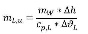
Δh enthalpy of vaporization (which the circulating air gives off to the product or the water film) Δh = r in kJ/kg*mW
The values also apply:
| ϑ | r |
cp,L |
| °C | kJ/kg | kJ/(kg*K) |
| 0 | 2500 | 1,006 |
| 100 | 2257 | 1,011 |
Fresh air flow
The fresh air flow is obtained from
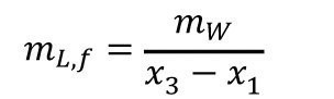
In a recirculating air dryer, two air volumes of different states are mixed. The, usually larger, recirculated air volume (x3; ϕ3; ϑ3;h3) with the smaller fresh air volume (x1; ϕ1; ϑ1;h1).
The resulting mixture is fed to the dryer before heating. The states are shown schematically in the h-x diagram (Fig. 9) .
The specific heat requirement for the supply air dryer is
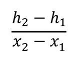
The following applies accordingly for circulating air drying
(with the data h0, x0 for the mixture) or
according to the similarity of the triangles.
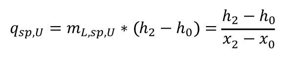
The mass of dry air for the evaporation of 1 kg of water is given by
and for the circulating air evaporator or circulating air dryer
The heat requirement per kg of water is correspondingly
It is provided by the heater and the fans.
An important aspect for all dryers in surface technology is to distribute the air flow as evenly as possible to all workpieces. The workpieces that the air passes by more slowly dry much longer than those with a higher air speed. However, the drying time is determined by the slowest process. In addition, the faster-drying workpieces heat up after the end of the evaporation process and are therefore more difficult to remove (gloves!). In addition, there are time and energy savings with uniform air circulation. Ensuring uniform air distribution is therefore a basic requirement of dryer design.
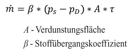
The basic properties of air flow around bodies are described in [1]. In the case of plate-shaped workpieces, the angle of flow plays a significant role in the size of the mass transfer coefficient (β in m/s) (Fig. 18).
 Fig. 18: Mass transfer coefficient on the plate-shaped workpiece as a function of the angle of attack
  Fig. 19: Mass transfer coefficient as a function of the flow velocity
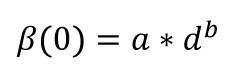
If the plate is parallel to the direction of flow, the mass transfer coefficient is the same on both sides. This changes when it is rotated. The dependence on the angle of attack a for the downstream side follows a function of the type
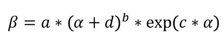
This means an initial sharp increase with increasing angle, a narrow maximum followed by a drop due to the exponential function. This means that the exponent c is always negative. The term d determines the mass transfer coefficient at zero angle of attack.
The maximum shifts to higher angles with increasing inflow length; from approx. 10° at 40 mm length up to 45° at 300 mm inflow length. At the same time, it decreases slightly as the angle of attack increases.
For the opposite side, the mass transfer coefficient increases slightly and approximately linearly from the same initial value (for α = 0) up to an angle of 90°. If you wanted to achieve uniform drying in this case, the plate would have to rotate slowly. This method is also used for solvent evaporation after painting. There are similar problems with cylindrical workpieces, where "dead water" forms opposite the flow point.
The above makes it clear that the dryer must always be slightly oversized in order to dry all workpieces at all points.
Another problem is the flow cross-section. On the fabric, it must be based on the size of the fabric. Relatively small cross-sections are required for optimum dimensioning of the fan. If the fan is positioned in front of the fabric window, the cross-section in this direction must be enlarged; if it is positioned behind it, it must be reduced. In the case of the circulating air dryer, both must be achieved. Directly around the workpieces, the cross-section is reduced and the flow is disturbed.
While the flow in the narrowing part (nozzle-like part) can be left to itself, it is advisable to support it in the diffuser (widening flow channel) with guide plates. This is necessary because the flow does not expand evenly in all directions and often leans against a wall. The disadvantage of the increased pressure loss is compensated by the shorter drying time due to the more even distribution.
As the air flow is guided in a circle during air circulation drying, it must also be deflected. However, deflections also lead to highly uneven flow velocities. It is advisable to use sufficient radii and cleverly positioned baffles.
Air circulation dryers usually guide a powerful air flow in a circle over the goods. Only a small proportion is diverted as exhaust air and replaced by preheated fresh air.
The partial pressure difference
is the driving force for mass transport (moisture transport) [6].
The following applies to the amount of diffusing vapor
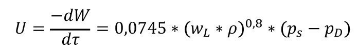
As it is adhesive water, the free film of the rinsing water, evaporation can be considered as evaporation from a free surface. The partial pressure remains constant until the film disappears. The following applies to the drying rate in kg/(m2*h) [6].
It is necessary to specify the unit, as this is what the figures refer to.
Other formula in kg/(m2*s) according to [4]
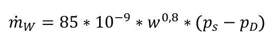
The unit is also important here because the numerical values change as a result. The higher air speed leads to correspondingly higher drying speeds for dryers with recovery at the same potential pressure difference. Due to the exponent 0.8 for the velocity or the Reynolds number, the increase is somewhat less than linear and decreases with increasing wind speed (Fig. 19).
Literature
[1] Unruh, J.N.M.: Trocknung - ein Stiefkind der galvano- technischen Fertigung, Jahrb. Oberflächentechnik 74, Eugen G. Leuze Verlag, Bad Saulgau, 2018, 134-151
[2] Unruh, J.N.M.; "Galvanotechnik" 116, 10, Leuze Verlag, Bad Saulgau, 2018, 1951-1956
[3] Kröll, K.: Trocknungstechnik, 2nd vol, 2nd ed., Springer, Bln., Hdlbg, NY, 1978
[4] Pawlow, K.F.; Romankow, P.G.; Noskow, A.A.: Beispiele und Übungsaufgaben zur chemischen Verfahrenstechnik, 5th ed, Dt. Verl. f.d. Grundstoffindustrie, Leipzig, 1975
[5] www.harter-gmbh.de
[6] Lysjanski, V.M. u.a: Verfahrenstechnische Grundlagen der Lebensmitteltechnik, Springer, Wiesbaden, 1983
[7] FSTDrytec, product presentation Sternenfels, 18.01.201
