- Part 1 - Experimental work: Electrolyte preparation and electroforming with planar substrate
In order to meet the expectations for a similar range of electric cars compared to combustion vehicles, lithium-ion batteries must be further developed. The two electrodes offer potential. This paper presents the production of aluminum current collector foils. An ionic liquid based on aluminum chloride (AlCl3) and 1-ethyl-3-methyl-imidazolium chloride [EMIm]Cl in a molar ratio of 1.5:1 serves as the electrolyte. Electroforming is investigated on substrates made of different materials and with different geometries. By characterizing the films using light and scanning electron microscopy, correlations between the deposition conditions and the microstructure of the films can be established.
Introduction
In 2015, 195 parties signed the Paris Agreement on climate change. It stipulates that global warming is to be limited to well below 2 °C and preferably below 1.5 °C compared to pre-industrial temperature levels [1]. In Germany, the Climate Action Plan 2050 [2] was adopted by the federal government to meet the targets. It contains targets that specify the maximum number of tons ofCO2 equivalents that may be emitted per sector in 2030. The transport sector accounts for the third-largest share of greenhouse gas emissions in 2020 at around 20%, of which 96% (in 2019) is attributable to road traffic. In order to reduce emissions in road traffic, a switch from combustion engines to electric motors is to take place, as electric cars have a lowercarbon footprint over their entire life cycle than cars with combustion engines [3]. According to a forecast by the Federal Motor Transport Authority, 24.4% of all cars in Germany in 2030 (this corresponds to 11.55 million units) will already be powered by an electric motor [4]. Electric motors convert electrical energy into mechanical energy and thus drive the car. Electrochemical storage systems are used to store the electrical energy required for this. In addition to ecological and economic aspects, the requirements for the storage units include fast charging capability (fast power consumption) and fast power output. At the same time, the volume and weight of the storage units should be as low as possible, i.e. their power density and specific power should be as high as possible, while maintaining a high energy density and specific energy [5]. Lithium-ion batteries (LIBs) are currently used in battery electric vehicles (BEVs), as this battery technology represents the best compromise between the requirements [6]. In order to meet the expectations for a similar range of BEVs compared to vehicles with combustion engines, LIBs must be further developed [7]. The two electrodes offer potential for this. In addition to the active materials used and their proportion in the respective electrode, the electrode structure also has a decisive influence on cell performance [8].
A new process for the production of battery electrodes was developed and patented in the working group of Prof. Dr. Timo Sörgel [9]. The so-called composite electroforming process (see also the report in Galvanotechnik 1/2024) makes it possible to produce cathode foils in a single-stage process that completely dispenses with the use of binders and conductive additives. An electrochemically deposited metallic matrix takes over these functions and also serves as a current collector. As part of several publicly funded research projects, the process has been scaled up from the beaker to the pilot plant scale. So far, cathodes for lithium-sulphur batteries have been produced [10][11][12][13][14].
The application of the process for the production of cathode foils for LIBs has also been investigated [15]. In both cases, nickel is essentially used as the matrix metal. In order to further increase the specific performance of a LIB with composite electroformed cathode foil, the replacement of the matrix metal offers a promising approach. The use of aluminum, with its lower density and the highest electrical conductivity by mass, seems very promising here [16]. As part of the AiF-funded research project "KultBat - Composite electroformed ultra-power-dense cathodes for lithium-ion batteries", a process is therefore to be developed together with the working group of Prof. Dr. Bund (TU Ilmenau) that enables the composite electroforming of cathode foils with aluminum as a matrix metal for use in LIBs.
One work package of the project provides for the electroforming of aluminum foils as a preliminary stage of composite electroforming. To date, there have only been a small number of scientific publications on this subject. For example, Tu et al [17] reported on the electroforming of aluminum foils with a graphite disc electrode with a diameter of 10 mm from the ionic liquid AlCl3 - 1-butyl-3-methyl-imidazolium chloride (molar ratio 2:1) using a three-electrode setup. Further work was carried out by Ui et al [18,19,20, 21,22,23] on electroforming aluminum foils with a smooth surface by pulse deposition and/or addition of 1,10-phenanthroline anhydrate to the electrolyte AlCl3-1-ethyl-3-methyl-imidazoliumchloride ([EMIm]Cl) (molar ratio 2:1). Experimentally, a titanium sheet with an area of 0.95cm2 was used as the cathode. Ruan et al. reported that they prepared free-standing Al-Mn alloy films by dissolving the copper substrate in nitric acid after electrodeposition of AlCl3 - [EMIm]Cl (molar ratio 2:1) with MnCl2 [24].
In the present work, the electroforming of aluminum foils from the ionic liquid AlCl3 - [EMIm]Cl in a molar ratio of 1.5:1 was investigated. For this purpose, experiments were first carried out with planar substrates made of different materials in order to determine a suitable substrate material. A rotating cylinder was then used as a substrate for electroforming larger aluminum foils.
Experimental work
An electrolyte based on [EMIm]Cl was used for the electrochemical deposition of aluminum. As this is hygroscopic and at the same time sensitive to hydrolysis, both the electrolyte preparation and all deposition experiments had to be carried out in a protective atmosphere. For this purpose, a glovebox (LABStar 1200, M. BRAUN INERTGAS-SYSTEME GmbH, Garching) was used, the bottom of which was first lined with a glass fiber reinforced polytetrafluoroethylene (PTFE) film (PLOFLON, W+B Datentechnik GmbH, Hagen) for protection. Nitrogen (≥ 99.9999% Nippon Gases Deutschland GmbH, Düsseldorf) was used as the shielding gas, as it is cheaper than argon of the same purity. The water and oxygen contents were generally < 0.5 ppm.
Electrolyte preparation
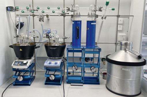
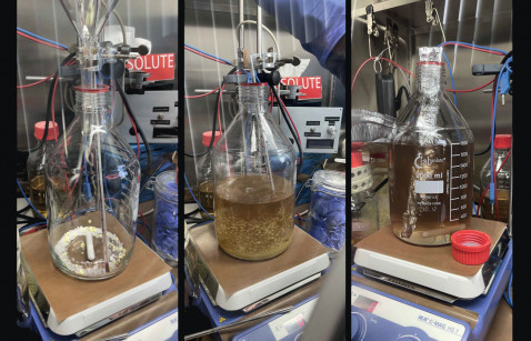
Two electrolytes consisting of AlCl3 and [EMIm]Cl in a molar ratio of 1.5:1 were used for aluminum deposition. A volume of 1.75 l was prepared for each, requiring 1000 g [EMIm]Cl and 1364 g AlCl3. One electrolyte was already prepared and purified from previous work. For this, [EMIm]Cl of purity > 95 % (IoLiLyt 0093, IoLiTec Ionic Liquids Technologies GmbH, Heilbronn) was used. The preparation of the second electrolyte was carried out with purer [EMIm]Cl (> 98 %, IL-0093-HP-1000, IoLiTec Ionic Liquids Technologies GmbH, Heilbronn) and is described here. The AlCl3 granulate (99 %, abcr GmbH, Karlsruhe) was weighed out in the glovebox in laboratory bottles and could be used for the preparation without further treatment. The [EMIm]Cl was introduced into the glovebox and transferred to two 1000 ml round-bottom flasks. As water was still bound in the salt, it first had to be removed by drying. To do this, the round-bottom flasks were each placed in an oil bath and connected to a Schlenk line. A gas cylinder with argon (> 99.999 %, Nippon Gases Deutschland GmbH, Düsseldorf) and a vacuum pump were connected to the Schlenk line. To prevent damage to the vacuum pump by potentially harmful gases that could enter the pump, two cold traps were installed between the Schlenk line and the vacuum pump. During operation, the cold traps were each immersed in a Dewar vessel filled with liquid nitrogen in order to freeze out any escaping gases. After connecting the pistons to the Schlenk line, they were first flushed with argon for one minute. Vacuum was then slowly drawn and the temperature of the oil bath was set to 60 °C. In total, the salt was dried for 52 h under vacuum (< 10 mbar) at 60 °C. The experimental setup for drying the [EMIm]ClI is shown in Figure 1 . To ensure that the water content of the salt was below 100 ppm, it was then measured using Karl Fischer titration (831 KF Coulometer + 774 Oven Sample Processor, Deutsche METROHM GmbH & Co. KG, Filderstadt). Once the residual moisture content of the salt had been determined, the electrolyte preparation was started in the glovebox. For this purpose, a 50 mm long magnetic stirring rod was placed in a 2000 ml laboratory bottle and the bottle was placed on a magnetic stirring plate (IKA magnetic stirrer C-MAG HS 7 digital, IKA-Werke GmbH & CO. KG, Staufen). A glass thermometer was inserted into the open bottle so that the temperature could be monitored during the preparation. A glass funnel for the AlCl3 and the [EMIm]Cl was alternately attached to a stand. At the beginning, a very small amount of [EMIm]Cl was added to the bottle with a spatula, the funnel was changed and an equally small amount of AlCl3 was added. The stirring speed was then set to approx. 185 rpm. Small amounts of both salts were then added alternately and waited until the mixture had completely liquefied. Care was always taken to ensure that the temperature remained below 60°C if possible, but in any case below 80°C, as thermal decomposition of the electrolyte is to be expected [25]. As the addition of the salts progressed, the stirring speed was also gradually increased. After both salts had been completely added and dissolved, stirring was continued at approx. 600 rpm for a further 24 h in order to obtain a homogeneous electrolyte. As the AlCl3 used, and therefore also the electrolyte, is contaminated with iron due to the manufacturing process and impurities can have a negative effect on the deposition behavior, this should be removed from the electrolyte by cementation. For this purpose, three strips of approx. 30 cm x 30 cm were cut from a commercially available aluminum foil (Cofresco Frischhalteprodukte GmbH & Co. KG, Minden), wiped with isopropanol, rolled up into a loose coil and placed in the unheated electrolyte for 72 hours. The electrolyte was stirred for approx. 12 h at approx. 450 rpm. The experimental setup is shown in Figure 2 , on the left at the beginning, in the middle during the preparation and on the right during purification with aluminum foil. After removing the aluminum foil, the electrolyte was filtered through a glass fiber filter (0.5 μm pore size, BIOZOL Diagnostica Vertrieb GmbH, Eching) using a vacuum pump (Bürkle GmbH, Bad Bellingen) and a round bottom flask with a Büchner funnel and was ready for use. Fig. 1: Setup for drying (EMIm)Cl with a Schlenk line
 Fig. 2: Set-up for preparing the electrolyte at the beginning (l.) and during preparation (m.) as well as during purification with aluminum foil (r.)
Electroforming with planar substrate
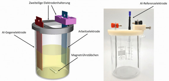
To ensure reproducible experiments in electroforming with a planar substrate, a two-part holder was designed to fix the working and counter electrodes in the beaker and produced using 3D printing from polyvinyl alcohol (nicePVA Natur, nice-shops GmbH, Paldau, Austria). Two holes were made in the holder to fix the temperature sensor and the reference electrode. The design allows the working and counter electrodes to be aligned parallel to each other without any additional aids and the working electrode can be removed or inserted very easily. Sheet metal blanks made of 2.0 mm thick aluminum (99.99 %, abcr GmbH, Karlsruhe) were used as counter electrodes. These were etched in 20 % sodium hydroxide solution before use and then cleaned with isopropanol. The shape of the electrode was chosen so that it was fixed in the electrode holder and stable in position. For the reference electrode, an aluminum wire (≥ 99.999 % Puratronic, Thermo Fisher Scientific GmbH, Dreieich, Germany) with a diameter of 1.0 mm was placed in a ground glass Pasteur pipette and cast with acrylic adhesive. This provides mechanical stability and makes the wire easier to handle. The wire protruding from the thin end of the pipette was cut off and ground to 5.0 mm. At the other end, the wire was connected to a socket for banana plugs by crimping. The area between the pipette and the socket, where the wire was exposed, was reinforced by attaching two shrink tubes to mechanically stabilize the wire. The CAD model of the electrode holder with beaker and working and counter electrode is shown on the left and the real setup including reference electrode on the right in Figure 3. Fig. 3: CAD model (left) and real setup for deposition experiments without electrolyte (right) including the 3D-printed electrode holder. Not included in both figures are the temperature sensor, the reference electrode on the left and the magnetic stirring bar on the right
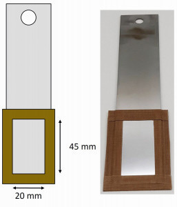
Substrates made of different materials were tested for the electroforming of aluminum foils. These were unalloyed (1.0330) and high-alloy steel (1.4301, both Hans-Erich Gemmel & Co. GmbH, Berlin), molybdenum (99.95 %, WHS Sondermetalle GmbH & Co. KG, Grünsfeld) and glassy carbon (SIGRADUR G, HTW Hochtemperatur-Werkstoffe GmbH, Thierhaupten). The two steel samples were first brushed and polished. Residues of the polishing paste were then removed with isopropanol before the samples were ultrasonically degreased for 10 minutes at 50 °C (SLOTOCLEAN AK 340, Dr.-Ing. Max Schlötter GmbH & Co. KG, Geislingen an der Steige) and rinsed with deionized water and isopropanol. To produce a defined reproducible surface, the steel substrates were additionally passivated in nitric acid (pure, Stierand GmbH, Waldstetten) and the molybdenum substrate was treated with a hydrochloric acid solution (pure, Stierand GmbH, Waldstetten). The parameters for this were taken from Rituper [26] and are listed in Table 1 . In order to obtain a defined surface and reduce edge effects, the rear side of the substrates was completely covered and the front side was covered with a frame of glass fiber reinforced PTFE film. The area left free was 9 cm2 and was then cleaned with isopropanol. Figure 4 shows a schematicrepresentation of a substrate prepared in this way (left) and an example made of high-alloy steel (right). Fig. 4: Schematic representation (left) and an example of a substrate prepared from high-alloy steel (right) for the electroforming experiments
For the deposition experiments, 600 ml of the existing electrolyte was added to the beaker, which was stirred using a magnetic stirring bar (35 mm, approx. 250 rpm) and a magnetic stirring plate (IKA magnetic stirrer C-MAG HS 7 digital, IKA-Werke GmbH & CO. KG, Staufen) and heated to 50 °C. The target layer thickness was 15 µm. The target layer thickness was defined as 15 μm. The current densities used were determined from previously recorded cyclic voltammograms. They are shown with the corresponding exposure times in Table 2 for the respective substrate material. The exposure times were calculated assuming 100% Faraday efficiency. A potentiostat (VSP with booster VMP3B-20 20A/20V, Biologic Science Instruments GmbH, Seyssinet-Pariset, France) was used for these and all subsequent deposition experiments in this work.
After deposition, the respective substrate was removed from the electrolyte and excess electrolyte was removed by dripping and wiping with a laboratory paper towel. It was then removed from the glovebox, immediately rinsed with isopropanol, followed by deionized water, and carefully dried with compressed air. Before removing the layer, the PTFE film was removed from the substrate and the rinsing and drying process was repeated. The layer was then removed from the substrate using a scalpel. Continued in Galvanotechnik 3/2024
|
Substrate material |
Preparation |
Temperature [°C] |
Duration [min] |
|
Unalloyed steel |
125 ml HNO3 65 % |
20 |
20 |
|
High-alloy steel |
25 ml HNO3 65 % |
50 |
20 |
|
Molybdenum |
30 ml HCl 37 % |
20 |
20 |
Table 1: Preparation data of the solutions and parameters for pretreatment of the metallic substrates for electroforming
|
Substrate material |
Current density [mA/cm2] |
Exposure time [min:s] |
Temperature [°C] |
|
Unalloyed steel |
16,3 |
44:24 |
50 |
|
High-alloy steel |
16,9 |
42:50 |
50 |
|
Molybdenum |
16,4 |
44:03 |
50 |
|
Glassy carbon |
17,6 |
41:05 |
50 |
Table 2: Current densities and exposure times for electroforming 15 μm thick aluminum foils with different substrate materials
Literature
[1] United Nations, Paris Agreement, 2015.
[2] Federal Ministry for the Environment, "The Climate Action Plan 2050 - Germany's long-term climate protection strategy", available at https://www.bmu.de/WS3915, 2020.
[3] Federal Government, "Klimaschonender Verkehr", available at https://www.bundesregierung.de/breg-de/themen/klimaschutz/klimaschonender-verkehr-1794672.
[4] Federal Motor Transport Authority, "Forecast: More than eleven million electric cars and plug-ins by 2030", available at https://www.autohaus.de/nachrichten/autohandel/prognose-mehr-als-elf-millionen-elektroautos-und-plug-ins-bis-2030-2697632.
[5] J. Deng, C. Bae, A. Denlinger, T. Miller, Joule (2020) 4, p.511
[6] A. Eftekhari, ACS Sustainable Chemistry & Engineering (2019) 7, p. 5602.
[7] K. Turcheniuk, D. Bondarev, G. G. Amatucci, G. Yushin, Materials Today (2021) 42, p. 57.
[8] M. Armand, P. Axmann, D. Bresser, M. Copley, K. Edström, C. Ekberg, D. Guyomard, B. Lestriez, P. Novák, M. Petranikova et al, Journal of Power Sources (2020) 479, 228/708.
[9] T. Sörgel, S. Meinhard, S. Sörgel, EP 3 114 721 B1, 2015.
[10] C. Erhardt, S. Meinhard, S. Sörgel, T. Sörgel, Galvanotechnik (2015) 106, p. 2396.
[11] C. Erhardt, Ş. Sörgel, S. Meinhard, T. Sörgel in Jahrbuch Oberflächentechnik (ed.: T. Sörgel), Eugen G. Leuze Verlag, Bad Saulgau, Germany, (2015) pp. 198-209.
[12] C. Erhardt, Ş. Sörgel, S. Meinhard, T. Sörgel, Journal of Power Sources 70 (2015) 296
[13] A. K. Jäger, S. Meinhard, O. Kesten, I. Hägele, T. Sörgel WoMag (2020) 4, p. 25.
[14] S. Meinhard, O. Kesten, K. Jäger, I. Hägele, T. Sörgel, Galvanotechnik (2020) 8, p. 1164.
[15] BMBF project "LiMaProMet" (FKZ: 13FH4I02IA), Future Li-based energy storage systems: New material systems, manufacturing processes and quality assessment methods in the overall project "Smart materials and intelligent production technologies for energy-efficient products of the future (SmartPro)", 2017-2021.
[16] W. M. Haynes (ed.) CRC Handbook of Chemistry and Physics. A ready-reference book of chemical and physical data, 97th Edition, CRC Press, Boca Raton, London, New York, 2017.
[17] Tu, X.; Zhang, J.; Zhang, M.; Cai, Y.; Lang, H.; Tian, G.; Wang, Y. RSC Adv. (2017) 7, 14790.
[18] Ui, K.; Kobayashi, S.; Sasaki, K.; Takeguchi, T.; Tsuda, T.; Ueda, M.; Nunomura, J.; Honkawa, Y.; Kojima, Y. J. Electrochem. Soc. (2021) 168, 56510.
[19] Ui, K.; Kobayashi, S.; Takeguchi, T.; Tsuda, T.; Ueda, M.; Nunomura, J.; Honkawa, Y.; Oya, Y.; Kojima, Y. Meet. Abstr. 2021, MA2021-02, 723.
[20] Ui, K.; Kobayashi, S.; Takeguchi, T.; Tsuda, T.; Ueda, M.; Nunomura, J.; Honkawa, Y.; Kojima, Y. Meet. Abstr. 2020, MA2020-02, 3002.
[21] Ui, K.; Kobayashi, S.; Kono, M.; Takeguchi, T.; Tsuda, T.; Ueda, M.; Nunomura, J.; Honkawa, Y.; Oya, Y.; Kojima, Y. (Digital Presentation) ECS Trans. 109 (2022) 105.
[22] Ui, K.; Kobayashi, S.; Mandai, T.; Takeguchi, T.; Tsuda, T.; Ueda, M.; Nunomura, J.; Honkawa, Y.; Kojima, Y. Meet. Abstr. 2019, MA2019-02, 961.
[23] Ui, K.; Kobayashi, S.; Takeguchi, T.; Tsuda, T.; Ueda, M.; Nunomura, J.; Honkawa, Y.; Kojima, Y. ECS Trans. 2020, 98, 223.
[24] Ruan, S.; Schuh, C.A. J. Mater. Res. (2012) 27, p. 1638.
[25] R. Böttcher, personal communication, 2022.
[26] R. Rituper, Beizen von Metallen, 1st edition, Eugen G. Leuze Verlag, Saulgau, Württ., Germany 1993.


