
After a new methodological approach to the development of REACh-compliant alternatives for Zn-Ni alloy coatings was presented in the first part of the publication, the second part presents key results, particularly with regard to the chemical composition, corrosion resistance, microstructure and scratch resistance of the coatings. It is shown that Zn-Fe-Mo alloy coatings already form corrosion-resistant top layers in the alternating climate test and exhibit high corrosion resistance in conjunction with an adapted passivation. Pulse plating can be used to produce particularly fine-grained coatings with a high current yield. Layers with low roughness are deposited even without the addition of the peak brightener. In addition, the use of a tip brightener and pulsed current conduction even results in superior scratch resistance compared to commercial Zn-Ni coatings. Upscaling shows that the results achieved using a robot-assisted electroplating system can be transferred to an industrial scale.
Introduction
Against the background of a possible restriction on the use of Zn-Ni alloy coatings as a result of the REACh regulation, there is a need to establish REACh-compliant alternatives. At the present time, Zn-Fe alloy coatings are primarily being considered as substitutes for Zn-Ni, although they are inferior to zinc-nickel coatings in terms of corrosion resistance [1] and coating hardness [2]. As part of the joint project "REACh-compliant corrosion protection through pulse plating" (ReKoPP), research was therefore carried out into the deposition of alternative, ternary coating systems. A novel methodological approach was used, which included the pre-selection of promising electrolyte systems based on thermodynamic and kinetic calculations as well as the design, installation and commissioning of a robot-assisted electroplating system (LaborRob) for the fully automated processing of statistical test plans [3]. One result of the research work is the development of Zn-Fe-X alloy coatings (where X = Sn, Mo, Mn, Cu, In, ...).
The composition and microstructure of metallic coatings can be strongly influenced by the application of pulse plating. The application of short current or voltage pulses with high amplitude enables the setting of extreme deposition conditions in the limiting current range, whereby sufficiently long pulse pauses enable the regeneration of the metal ion concentration at the cathode. Against this background, pulse plating makes it possible to develop completely new alloy compositions. The current pauses also interrupt grain growth, and high pulse current densities promote the formation of many new crystallization nuclei. Pulse plating can therefore be used to produce particularly fine-grained coatings with increased hardness and high ductility. The grain-refining and hardness-increasing effect of pulsed current conduction has already been demonstrated on Zn-Ni coatings [4]. Grain refinement can also lead to an increase in the gloss of Zn alloy coatings [5], so that in the ideal case top brighteners can be dispensed with in favor of simplified bath management.
In this study, the entire electrolyte and process development procedure is illustrated using the Zn-Fe-Mo system as an example. The development goals are to produce homogeneous, corrosion-resistant and abrasion-resistant coatings and to transfer the process parameters to an industrial scale.
Experimental
The development of the Zn-Fe-X basic electrolyte was based on the thermodynamic and kinetic calculations described in [3]. Different metal salts for the deposition of Zn-Fe-X alloy layers (X = Sn, Mo, Mn, Cu, In, ...) were added to the Zn-Fe electrolyte obtained in this way. The subsequent additive development was carried out using electrochemical "in situ" impedance spectroscopy. Here, the gloss formation of additives, as shown in Figure 1 , can be predicted on the basis of the determined double layer capacity. With this method, statements on the mode of action of organic brighteners can be obtained very quickly and, compared to large-scale deposition tests, significantly lower electrolyte volumes are sufficient. This saves valuable raw material resources and avoids waste.
The most promising ternary alloy layers in terms of external appearance and current yield were characterized with regard to their passivation behaviour, which is important for corrosion behaviour under atmospheric conditions. As an alternative and in addition to the neutral salt spray test commonly used in industry, which is not very informative with regard to passive layers, a test using gel electrolytes (6) developed at the Federal Institute for Materials Research and Testing (BAM) was used. In order to generate application-oriented passive layers, exposure tests were first carried out for up to 21 days in a KB 300 climatic chamber from Liebisch Labortechnik. Each weathering cycle consisted of a wet phase (95 % RH for 2 h, 28 °C) followed by a dry phase (60 % RH for 4 h, 21 °C). The samples were taken for the accompanying electrochemical tests using the gel electrolyte at the end of each dry phase. In contrast to conventional, aqueous test media, no time-dependent dissolution of the natural passive layer occurs when using the gel electrolyte.
This makes it possible to quantitatively evaluate the formation of an overcoat, as observed under atmospheric conditions. The procedure for determining the surface layer resistance is described in detail in [6]. To better classify the corrosion resistance in comparison to established coatings, selected coated and partially passivated components were also tested using a neutral salt spray test in accordance with DIN EN ISO 9227.
To investigate the parameter space during pulse plating of the Zn-Fe-Mo alloy, statistical test plans were drawn up, processed fully automatically using the robot-assisted electroplating system described in [3] and evaluated using neural networks. Further details on the design and operation of the robot-assisted electroplating system can be found in [7] and [8]. Copper sheets measuring 100 × 70 × 0.5 mm3 were used as substrate materials, with a coating area of 100 × 50 mm2 after masking of the rear side and the upper sheet section. The pre-treatment included degreasing, pickling and rinsing in the cascade rinse after each treatment step. To investigate the leveling effect of the pulsed current, the addition of the top brightener (hereinafter also referred to as "additive") was initially omitted. A unipolar rectangular pulse (current pulse followed by a current pause) was always selected as the current form. After the coating process, the sample was rinsed again, dried and deposited.
Characterization always included photographic documentation of the coating result during the process as well as determination of the coating thickness and alloy composition using X-ray fluorescence analysis (XRF, Fischerscope - X-RAY XAN, Fischer). To increase measurement accuracy, the chemical composition of the alloy layers was also determined after dissolution using optical emission spectrometry with inductively coupled plasma (ICP-OES, Optima 8300, Perkin Elmer). The microstructure was analyzed using scanning electron microscopy (SEM, LEO1455VP, Zeiss) and X-ray diffraction analysis (XRD, D8 Discover, Bruker AXS). For comparative evaluation of the coating hardness and scratch resistance, round samples (diameter: 40 mm, height: 10 mm) were first coated with selected (pulse) current parameters for an increased process duration in a beaker in order to set coating thicknesses of at least 20 µm. The coating hardness was determined on the coating cross-section at at least 10 measuring points per sample by means of registering hardness measurement (Fischerscope HM2000 XYm, Fischer) at a maximum test load of 25 mN approximately in the middle of the coating cross-section. The scratch test was carried out with a constant normal force of 15 N, a scratch length l of 10 mm and a feed rate of 5 mm/min. The tangential force Ft was recorded during the scratch test using the Revetest device (CSM Instruments). A stylus instrument (T 4000, Hommelwerke) was used to determine the scribe cross-sectional area A. The scribe energy density WR indicates the mechanical work required to displace a certain volume of material. It is therefore a quantitative characteristic value for scribe resistance and is calculated using the following formula:
In the course of upscaling, particularly promising coating parameters were used by the project partners Gazima GmbH and B+T Oberflächentechnik GmbH on a pilot plant scale for coating real components.
Knowledge-based electrolyte development
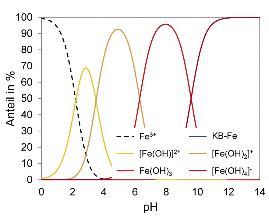
To develop a new ternary Zn-Fe-X electrolyte, different complexing agents were first selected that are suitable for the deposition of Zn alloy layers in terms of decomposition kinetics. Thermodynamic calculations were then used to calculate the stability ranges of different species and derive suitable working ranges. Using the selected complexing agent (KB), Zn2+ is almost uncomplexed up to around pH 5. In the pH range between about 6 and 10, compounds of the complexing agent with Zn and Zn hydroxide dominate (Fig. 2 left). Due to the low iron concentration in the electrolyte, the strong hydroxide complexes exist over a wide pH range. At around pH 8, iron is present in the form of the sparingly soluble Fe(OH)3 (Fig. 2 right). From around pH 10 to pH 13, zinc forms the sparingly soluble hydroxides Zn(OH)2 and M[Zn(OH)3]. Therefore, from a thermodynamic point of view, only a working range above pH 13 can be considered for this system.
 und Fe (rechts) in Abhängigkeit des pH-Werts im komplexierten Elektrolyten") Fig. 2: Species distribution for Zn (left) and Fe (right) as a function of the pH value in the complexed electrolyte
Fig. 2: Species distribution for Zn (left) and Fe (right) as a function of the pH value in the complexed electrolyte
Passivation behavior of ternary alloy layers
The incorporation of a third element into the Zn alloy layer directly influences the chemical composition of the natural passive layer and thus generally also the corrosion resistance. Research into the passivation behavior as a function of the layer composition is therefore an important criterion when selecting a specific alloy system.
The potentiodynamic polarization tests carried out on the different Zn alloy layers using gel electrolyte initially make it clear that the corrosion resistance is generally increased by the passive layer formation that takes place during ageing in the climate chamber. This can already be seen from the shift in the polarization curves towards lower corrosion current densities and a tendency towards somewhat nobler free corrosion potentials. Figure 3 confirms the hypothesis put forward at the beginning, according to which the corrosion resistance (quantified below by the coating resistance) is strongly dependent on the coating composition. This clearly shows that the conductivity of the naturally formed passive layer is in some cases significantly influenced even by low alloy contents (always less than one percent). The addition of indium, for example, results in a reduction of the surface layer resistance to the level of an unalloyed Zn layer. The addition of Mo, on the other hand, has only a minor effect on the
only slightly influenced. It can be assumed that Zn-Fe-Mo coatings have the best corrosion resistance of the ternary alloy coatings considered. The technical literature reports that the incorporation of mixed oxides and hydroxides containing molybdenum into the passive layer leads to increased corrosion resistance to media containing chloride [9]. In addition, components with corrosion-protective Zn alloy coatings are generally not used without post-passivation. In this way, the time-consuming process of natural surface layer formation is shortened and additional, chemically particularly resistant compounds (e.g. chromium or silicon oxides) can be incorporated into the surface layer.
 Fig. 3: Development of the surface layer resistance over time after aging of various Zn alloy layers
Results of the robot-assisted coating tests
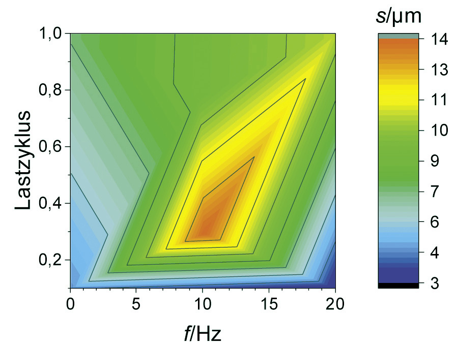
Now that Zn-Fe-Mo alloy coatings have proven to be a promising alternative in terms of their passivation behavior, the following section uses fully automated coating tests to show the extent to which the chemical composition of the coatings can be influenced by pulse plating. A suitable parameter space was narrowed down on the basis of initial orientation deposition tests in a beaker. The average current density was 1 or 2 A/dm2 with a constant charge quantity. In addition, the load cycle (ratio of the current pulse duration to the total pulse duration) and pulse frequency (number of pulse cycles per second) were varied. As can be seen from Figure 4 and Figure 5 , high Mo contents occur depending on the average current density at a low load cycle (high pulse current density) and/or high pulse frequency (short pause time). Very similar correlations can also be observed for the Fe content in the coating. High pulse current densities obviously lead to a depletion of the Zn ions in the diffusion layer with short pulse pauses, so that the alloying elements Mo and Fe are preferentially deposited. This behavior is also referred to as anomalous alloy deposition, as Zn is preferentially deposited at low current densities, although Fe and Mo actually have a more positive deposition potential in this system. Raub explains this phenomenon with the adsorption of Zn(OH)+ on the cathode surface, which makes the deposition of, for example, ions of the iron group elements more difficult compared to Zn deposition [10]. When the limiting current density is exceeded, there is also increased hydrogen evolution. This is associated with a lower current yield and consequently a lower layer thickness. It is therefore a challenge to simultaneously realize an economic current yield and the deposition of Mo in a Zn-Fe-Mo alloy layer.
 und der Schichtdicke nach 60 min Beschichtungszeit bei 1 A/dm2 (rechts) über der Pulsfrequenz und dem Lastzyklus") Fig. 4: Mapping of the Mo mass fraction determined by XRF in % (left) and the layer thickness after 60 min coating time at 1 A/dm2 (right) over the pulse frequency and the load cycle
Fig. 4: Mapping of the Mo mass fraction determined by XRF in % (left) and the layer thickness after 60 min coating time at 1 A/dm2 (right) over the pulse frequency and the load cycle
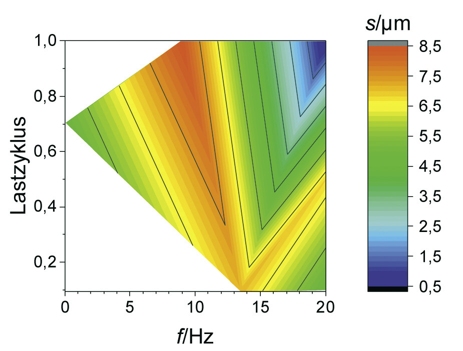
 und der Schichtdicke nach 30 min Beschichtungszeit bei 2 A/dm2 (rechts) über der Pulsfrequenz und dem Lastzyklus") Fig. 5: Mapping of the Mo mass fraction determined by XRF in % (left) and the coating thickness after 30 min coating time at 2 A/dm2 (right) over the pulse frequency and the load cycle
Fig. 5: Mapping of the Mo mass fraction determined by XRF in % (left) and the coating thickness after 30 min coating time at 2 A/dm2 (right) over the pulse frequency and the load cycle
An overlap of high coating thickness and moderate Mo content can be observed for an average current density of 2 A/dm2 at frequencies between 5 and 15 Hz and load cycles between 0.4 and 0.8. This parameter range was therefore considered again as part of a refined test plan. As can be seen from Figure 6 , a high film thickness can be achieved over a wide range of the parameter space. In particular, at a pulse frequency of 10 Hz, different alloy contents can be set over the load cycle with an almost constantly high coating formation efficiency. By evaluating the neural network, it is now possible to visualize the curves of the coating thickness and the alloy content over the load cycle, taking into account all available measurement data for this pulse frequency (Fig. 7). It was found that the Fe mass fraction decreases from about 0.4 percent to 0.2 percent with increasing load cycle. The Mo content is at least 0.2 percent over the parameter space under consideration and reaches a maximum value of around 0.6 percent at a load cycle of 0.8. In this system, ternary alloy layers can therefore be achieved with a high current yield and deposition rate.
 und der Schichtdicke nach 30 min Beschichtungszeit bei 2 A/dm2 (rechts) über der Pulsfrequenz und dem Lastzyklus") Fig. 6: Mapping of the Mo mass fraction determined by ICP-OES in % (left) and the coating thickness after 30 min coating time at 2 A/dm2 (right) over the pulse frequency and the load cycle
Fig. 6: Mapping of the Mo mass fraction determined by ICP-OES in % (left) and the coating thickness after 30 min coating time at 2 A/dm2 (right) over the pulse frequency and the load cycle

Coating microstructure and abrasion resistance
For the microstructural analysis, two pulse parameter sets for setting different Mo contents and a reference coating with direct current were specifically selected based on Figure 7 . The addition of the peak brightener was initially omitted. The aim was to investigate whether very flat coatings could be produced by pulse plating without the additive. The reference coating ("DC") deposited with direct current contains mass fractions of 1.4 % Fe and 0.1 % Mo. With the parameter set "60/40" (load cycle 0.6), a very uniform coating with the highest coating thickness (mean value: 14.2 µm), a lower Fe content of 0.32 % and a slightly increased Mo content of 0.18 % was deposited. For the pulse parameters "80/20" (load cycle 0.8), a uniform layer with a slightly lower layer thickness (mean value: 13.2 µm) as well as a low Fe content of 0.21 % and a high Mo content of 0.59 % was achieved. Electron microscopy (SEM) images initially confirm the macroscopic impression of uniform layer formation for the pulse plating layers (Fig. 8). However, it is noticeable that the Mo-rich layer "80/20" has a higher number of submicro- and microscale pores. These appear dark in the backscattered electron image (RE image, element contrast) and are mainly located in the interior of the layer (Fig. 8, right). It is reasonable to assume that in this case the long pulse and short pause duration result in a depletion of the Zn ions in the diffusion layer. This could explain the reduced current yield, the increased Mo content and the pores formed as a result of hydrogen evolution.
 Fig. 7: Evaluation using neural networks: curves of the layer thickness and the alloy content as a function of the load cycle z at a frequency of 10 Hz
 Fig. 8: RE images of the layer cross-sections of Zn-Fe-Mo layers deposited using the robot-assisted electroplating system, left: Pulse shape 60/40, right: Pulse shape 80/20
For the X-ray characterization (XRD) and the quantification of the abrasion resistance (scratch test), additional comparison samples were deposited with top brightener ("additive"). It is widely known that brighteners can cause a reduction in crystallite size as well as leveling due to adsorption on roughness peaks. In addition, the incorporation of organic compounds into the coating often results in a change in the residual stress state. As can be seen from Table 1 , however, the coatings deposited with additive ("m. A.") exhibit a comparable or even slightly increased crystallite size compared to the coatings deposited without the addition of additive ("o. A."). The crystallite size may already be so fine that the additive does not cause any further refinement. Pulse plating, on the other hand, leads to a pronounced grain refinement in both cases. Apparently, the formation of new grains is favored over the growth of existing grains by introducing a pulse pause. During the pulse, the same amount of charge flows for both pulse forms, so that the newly formed grains also have a similar size.
| Sample |
Crystal size in mm |
Main residual stresses in MPa σ1 σ2 |
Martens hardness in MPa |
| DC o. A. |
58 ± 1 |
-252 ± 6 -234 ± 4 |
1190 ± 90 |
| DC w. A. |
61 ± 2 |
-208 ± 5 -202 ± 3 |
1240 ± 60 |
| 60/40 o. A. |
32 ± 1 |
-177 ± 3 -161 ± 3 |
1490 ± 90 |
| 60/40 m. A. |
36 ± 1 |
-191 ± 4 -185 ± 3 |
1430 ± 70 |
| 80/20 o. A. |
32 ± 1 |
-215 ± 3 -199 ± 3 |
1420 ± 60 |
| 80/20 o. A.. |
32 ± 1 |
-215 ± 4 -207 ± 4 |
1440 ± 90 |
In the case of electrochemically deposited metallic layers growing in the thickness direction, the main residual stresses in the plane (σ1 and σ2) are theoretically the same. Even in the present measurements, the deviations between σ1 and σ2 are often only in the range of the measurement uncertainty. The main residual stress with the larger magnitude is always referred to as σ1. All layers show high residual compressive stresses. The layer deposited with direct current and without additive exhibits the highest residual compressive stresses. In this case, the residual stresses are reduced by adding additives. With pulse plating, an opposite trend or no significant influence is observed in some cases. The lowest residual compressive stresses were observed for the pulse parameters "60/40". This is generally advantageous in terms of coating adhesion.
Coating thicknesses of at least 20 µm were deposited on deflection-resistant round specimens specifically to determine the coating hardness on the cross-section and the scribe energy density using a scribe test with a constant load. Table 1 shows that pulse plating causes an increase in hardness from around 1200 N/mm2 to over 1400 N/mm2. Furthermore, a correlation between crystallite size and Martens hardness can be observed: In line with the Hall-Petch relationship for fine grain hardening, martensite hardness increases with decreasing crystallite size. Against this background, it is plausible that the addition of the peak brightener does not have a significant effect on the layer hardness, as it was not possible to reduce the crystallite size in this way. Furthermore, no clear correlation between the alloy content and the coating hardness can be identified. Apparently, fine grain hardening dominates over solid solution strengthening in this crystallite size range. The increased porosity shown in Figure 8 (right) after using the "80/20" pulse form does not have a significant effect on the Martens hardness, as the hardness measurements were only carried out in the middle of the layer and not in the more porous area close to the substrate. The highest Martens hardness (1490 MPa) is achieved with the "60/40" pulse form without the addition of additives.
The scribe energy density (Fig. 9) does not always correlate with the crystallite size and the resulting layer hardness. Rather, the relative differences in terms of scribe energy density can only be explained by a complex interaction of the microstructural characteristics of crystallite size, composition and porosity. Using the "60/40" pulse parameters, the abrasion resistance of a commercial Zn-Ni coating with a mass fraction of around 15 % Ni is almost achieved without the addition of the peak brightener. In contrast, no increase in scratch resistance is detectable with the "80/20" pulse form without additive. It is possible that the porosity close to the substrate shown in Figure 8 (right) impairs the scratch resistance. In any case, the scratch energy density of the Zn-Fe-Mo coatings increases with the addition of the peak brightener. Compared to the commercial Zn-Fe electrolyte, the fully additive Zn-Fe-Mo electrolyte enables the deposition of coatings with increased abrasion resistance even under direct current conditions. With the addition of additives, even higher scribe energy densities can be achieved compared to Zn-Ni. This means that the development goal of achieving abrasion resistance comparable to Zn-Ni was even exceeded.
 für Zn-Fe-Mo-Schichten, die mit unterschiedlichen Stromparametern, ohne und mit Additiv 10 abgeschieden wurden sowie für die kommerziell erhältlichen Referenzschichten Zn-Fe (ca. 0,5 % Fe) und Zn-Ni (ca. 15 % Ni).") Fig. 9: Scribe energy densities (normal force: 15 N, scribe length: 10 mm) for Zn-Fe-Mo coatings deposited with different current parameters, without and with additive 10, as well as for the commercially available reference coatings Zn-Fe (approx. 0.5 % Fe) and Zn-Ni (approx. 15 % Ni).
Fig. 9: Scribe energy densities (normal force: 15 N, scribe length: 10 mm) for Zn-Fe-Mo coatings deposited with different current parameters, without and with additive 10, as well as for the commercially available reference coatings Zn-Fe (approx. 0.5 % Fe) and Zn-Ni (approx. 15 % Ni).
Upscaling to industrial scale and corrosion behavior
The upscaling of the Zn-Fe-Mo system was carried out by the project partners B+T Oberflächentechnik GmbH (barrel process) and Gazima GmbH (rack process) on a pilot plant scale. In the rack process, various types of sheet metal components were coated using different current densities and pulse shapes. Particularly uniform and visually appealing coatings with a technical gloss resulted from a pulse frequency of 10 Hz and a load cycle of around 0.5 (Fig. 10 left). This corresponds very precisely to the pulse parameters that were also identified as particularly suitable for depositing homogeneous, abrasion-resistant coatings using the robot-assisted electroplating system at the TUC. The average current density could also be increased to 2.5 A/dm2 (instead of 2 A/dm²) to increase economic efficiency. The high compactness and homogeneity of the coating was also confirmed by light and scanning electron microscopy by the TU Chemnitz (Fig. 10 right).
, REM-Aufnahme (RE-Bild) der Schichtmikrostruktur am Querschliff") Fig. 10: Zn-Fe-Mo coating deposited on a pilot plant scale; macro image of coated sample components (left), SEM image (RE image) of the coating microstructure on the cross-section
Fig. 10: Zn-Fe-Mo coating deposited on a pilot plant scale; macro image of coated sample components (left), SEM image (RE image) of the coating microstructure on the cross-section
Due to the interrupted contact typical of the process, the same pulse parameters cannot be used for the barrel process as for the rack process. In order to achieve a reproducible effect, the pulse current and pause times must be either very short or very long compared to the contact times and pauses in the barrel process. In the present case, basically homogeneous Zn-Fe-Mo layers with a stepped effective current density (0.5 A/dm2 for 0.5 h and 1 A/dm2 for 1 h) were achieved. By using pulse plating (ton = 10 s,toff = 2 s), higher gloss surfaces could also be achieved without adding the peak brightener. This becomes clear from the comparison of c (direct current) and a (pulse plating) in Figure 11 . After application of a Cr(III)-based, Co-free blue passivation (b and d in Fig. 11), the demonstrator components have a very attractive appearance. In addition, the passivated Zn-Fe-Mo coatings meet the minimum requirement defined in DIN 50979 for Cr(VI)-free iridescent passivated Zn-Fe coatings with a thickness of 8 µm in the amount of 240 h test duration in the NSS without base material corrosion (red rust). As can be seen in Figure 12, only layer corrosion (white rust) can be detected on some surfaces of the passivated components.
 mit Pulsstrom, ohne Passivierung b) mit Pulsstrom und anschließender Blaupassivierung c) ohne Pulsstrom, ohne Passivierung d) ohne Pulsstrom, mit anschließender Blaupassivierung") Fig. 11: Components coated with Zn-Fe-Mo using the drum process on a pilot plant scale; a) with pulse current, without passivation b) with pulse current and subsequent blue passivation c) without pulse current, without passivation d) without pulse current, with subsequent blue passivation
Fig. 11: Components coated with Zn-Fe-Mo using the drum process on a pilot plant scale; a) with pulse current, without passivation b) with pulse current and subsequent blue passivation c) without pulse current, without passivation d) without pulse current, with subsequent blue passivation
 mit Pulsstrom, ohne Passivierung, b) mit Pulsstrom und anschließender Blaupassivierung c) ohne Pulsstrom, ohne Passivierung, d) ohne Pulsstrom, mit anschließender Blaupassivierung") Fig. 12: Components coated with Zn-Fe-Mo after 240 h salt spray testing in accordance with DIN EN ISO 9227; a) with pulse current, without passivation, b) with pulse current and subsequent blue passivation c) without pulse current, without passivation, d) without pulse current, with subsequent blue passivation
Fig. 12: Components coated with Zn-Fe-Mo after 240 h salt spray testing in accordance with DIN EN ISO 9227; a) with pulse current, without passivation, b) with pulse current and subsequent blue passivation c) without pulse current, without passivation, d) without pulse current, with subsequent blue passivation
In order to further increase the corrosion protection capacity of the newly developed Zn-Fe-Mo alloy coatings, it is necessary to adapt the passivation process according to the coating composition. With the help of a further developed nanopassivation with SiO2 nanoparticles, a particularly high resistance was achieved in the neutral salt spray test (NSS) in accordance with DIN EN ISO 9227. As can be seen in Figure 13 (below) , the component coated and passivated with Zn-Fe-Mo exhibits only isolated, localized passivation defects after 720 h in the NSS. In contrast, numerous defects in the passive layer and isolated layer corrosion (white rust) can already be seen on the component coated and passivated with Zn-Fe (Fig. 13 above). This proves that the newly developed, ternary Zn-Fe-Mo alloy layer in combination with an adapted passivation is excellently suited as corrosion protection for steel components.
 Fig. 13: Corrosion phenomena on coated and passivated components after 720 h salt spray test according to DIN EN ISO 9227, left: Zn-Fe, right: Zn-Fe-Mo
Conclusion:
As part of the joint project "REACh-compliant corrosion protection through pulse plating (ReKoPP)", it was shown that the knowledge-based preselection of suitable electrolyte systems and the exploration of parameter spaces using neural networks enable the time- and resource-efficient development of new types of alloy coatings. The experiments can be carried out fully automatically using a newly developed, robot-assisted electroplating system and the results are characterized by a high degree of objectivity, reproducibility and transferability to an industrial scale. New REACh-compliant alloy coatings have been developed, which are characterized by an attractive appearance, high corrosion resistance and superior abrasion resistance compared to commercially available Zn-Ni coatings.
Acknowledgments
The authors would like to thank the German Federal Ministry of Research and Education (BMBF) and the project management organization VDI Technologiezentrum GmbH for funding the project "REACh-compliant corrosion protection by pulse plating (ReKoPP)", promotional reference 13XP5031E. Funded project partners were: B+T Oberlächentechnik GmbH, Wetzlar; Coventya GmbH, Gütersloh; Gazima GmbH, Grünhain-Beierfeld; KleRo GmbH Roboterautomation, Berlin; plating electronic GmbH, Sexau; Chemnitz University of Technology.
Literature
[1] DIN 50962:2020-02: Electroplated coatings - Chromated zinc and zinc alloy coatings on ferrous materials
[2] A.C. Hedge; K. Venkatakrishna; N. Eliaz: Electrodeposition of Zn-Ni, Zn-Fe and Zn-Ni-Fe alloys, Surface & Coatings Technology 205 (2010), 2031-2041
[3] W. Paatsch; G. Mollath; T. Lampke; R. Morgenstern; H. Sahrhage; A. Reichenbach; J. Zimmermann; E. Kaufmann: Electrolyte development 4.0 using the example of ternary zinc alloys - Part 1: Basic approach, Galvanotechnik 111 (2019), 11, 1629-1634
[4] A.M. Alfantazi; U. Erb: Microhardness and thermal stability of pulse-plated Zn-Ni alloy coatings, Materials Science and Engineering A 212 (1996), 123-129
[5] H. Ashassi-Sorkhabi; A. Hagrah; N. Parvini-Ahmadi; J. Manzoori: Zinc-nickel alloy coatings electrodeposited from a chloride bath using direct and pulse current, Surface and Coatings Technology 140 (2001), 278-283
[6] M. Babutzka; A. Heyn: Dynamic tafel factor adaption for the evaluation of instantaneous corrosion rates on zinc by using gel-type electrolytes, IOP Conference Series: Materials Science and Engineering 181 (2017), 012021
[7] H. Klempnow; T. Behrendt; B. Szalkiewicz; G. Mollath; R. Morgenstern; T. Lampke: Successful digitalization in electroplating - The new colleague in the coating laboratory, Womag (2020), 11
[8] T. Lampke; R. Morgenstern: Robot-assisted electroplating system tested in research operation, ZVOreport (2020), 5
[9] J. Winiarski; W. Tylus; M.S. Krawczyk; B. Szczygiel: The influence of molybdenum on the electrodeposition and properties of ternary Zn-Fe-Mo alloy coatings, Electrochimica Acta 196 (2016), 708-726
[10] E. Raub: Galvanic alloy precipitation. Chemie Ingenieur Technik 45 (1973), 4, 167-174
