
Blasting is a manufacturing process that is little respected in science and can be used in the form of machining with geometrically indeterminate cutting edges to roughen or remove material and as a forming process to modify the surface. In the present study, angular abrasives are used on an aluminum alloy and a copper-zinc alloy. The effect of the process is described using microscope images. In addition, spherical abrasives are used and also described accordingly. The resulting roughness betweenRz = 10 to 20 µm is similar in both cases, even if the topography appears very different.
Basics and process overview
Blasting has been known for around 150 years as a manufacturing process in the main group "cutting" [1] and is assigned to the group "cutting with geometrically indeterminate cutting edges" because the angular blasting medium used for the corresponding applications does not have a specific edge angle. Blasting with spherical blasting media, where no cutting removal is desired but, for example, a hardening of the surface, belongs to the main group "Forming" and is classified there as "Forming blasting" with the classification number 2.1.6 or in the main group "Changing material properties" as "Hardening blasting" with the classification number 6.1.1. For many applications, the process is used intuitively and only for continuous production, such as fettling or for comparable series processing, is it examined more closely and adapted to the task.
![Abb. 1: Unterteilung von Varianten des Strahlens nach dem Strahlzweck (nach [5])](/images/stories/Abo-2020-09/Bild-1_mit_hinter_korr.jpg "Abb. 1: Unterteilung von Varianten des Strahlens nach dem Strahlzweck (nach [5])") Fig. 1: Subdivision of blasting variants according to the blasting purpose (according to [5])
Fig. 1: Subdivision of blasting variants according to the blasting purpose (according to [5])
DIN 8200 from 1982, in which the process was described, existed until 2008. The standard was then withdrawn without replacement. Today, the DIN EN ISO 8501 to 8504 series of standards and the DIN EN ISO 11124 to 11127 series, each with several parts, exist primarily for the "preparation of steel surfaces prior to the application of coating materials" and contain precise descriptions of the blasting media and procedures for testing the blasting media. In addition, there are individual standards for special purposes, such as DIN EN 4637 and 4638 or DIN 65468, each for the aerospace industry. General and relatively detailed descriptions of the process can already be found in several older sources [1-3] and specifically for shot peening in great detail in [4].
Shot peening is a very versatile manufacturing process and the most important processing objectives have already been listed schematically in [5] (Fig. 1). However, no distinction is made between the different types of blasting media or blasting systems, although these generally differ significantly. For example, fettling (fettling blasting) is almost always carried out with wheel blasting systems, whereas compressed air blasting systems are more suitable for surface finishing blasting.
A further classification of the process group distinguishes between the different blasting media (Fig. 2). The most frequently used blasting media in terms of quantity are ferrous metal blasting media, which are mainly used for fettling castings with wheel blast machines. For non-ferrous metal workpieces, blasting abrasives made of corresponding materials are used.
![Abb. 2: Einteilung der Strahlmittel (nach [2])](/images/stories/Abo-2020-09/Bild-2_korr.jpg "Abb. 2: Einteilung der Strahlmittel (nach [2])") Fig. 2: Classification of blasting abrasives (according to [2])
Fig. 2: Classification of blasting abrasives (according to [2])
Mineral blasting abrasives in fine grain sizes are particularly suitable for all types of compressed air blasting systems. Due to the risk of silicosis, natural sands may only be used in exceptional cases and corundum, slag or glass are particularly suitable for applications such as removal, roughening or matting. The organic, natural abrasives are used for particularly gentle processing during light deburring and the plastic granulates are also used for deburring work on thermosets.
for deburring work on thermosets or deep-frozen elastomers.
There are five different types of blasting systems (Fig. 3), for each of which some of the described blasting media are more or less suitable and which can be categorized not only by the strength of the blasting effect but also by the usual degree of automation. For example, wheel blast machines are often used for fettling castings in fully automated operation, while dry compressed air blast machines with fine-grained mineral abrasives are preferred for small to medium series in a more or less automated manner. Suction blasting systems are the most common, but they have a lower blasting effect than pressure blasting systems. Wet blasting systems are mainly used for fine cleaning work where as little as possible is to be removed from the workpiece. For the work described in this report, an RA24 injector suction blasting system from Lortz Strahlmaschinen GmbH was used.
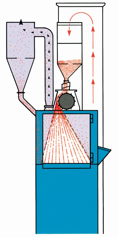
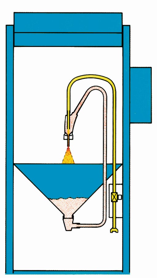
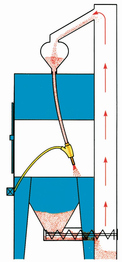
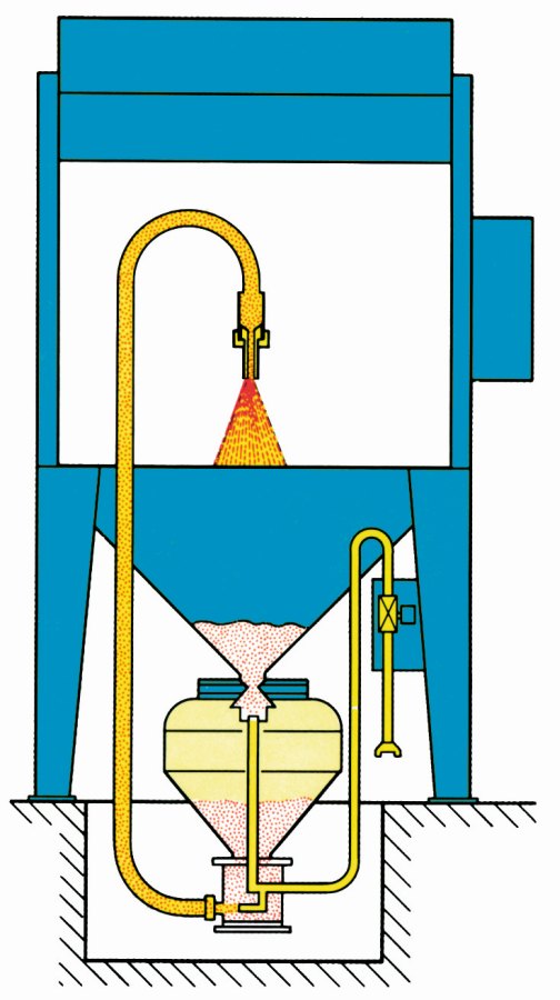
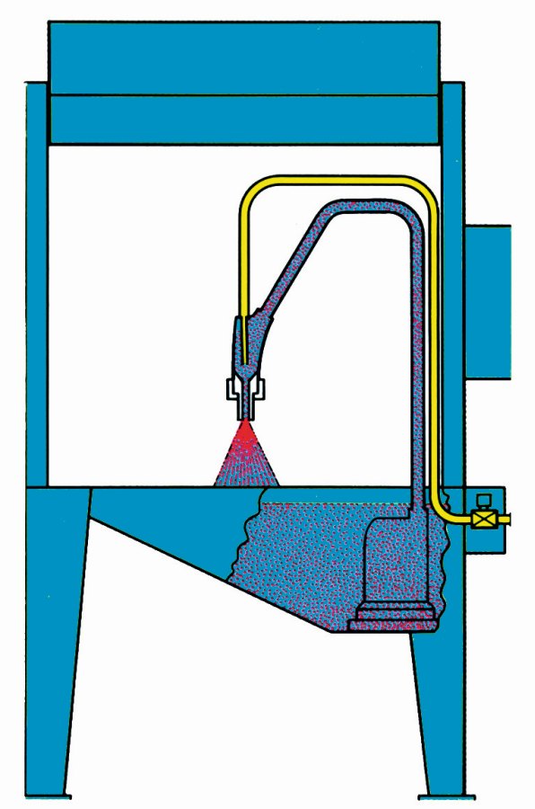
Fig. 3: Types of blasting systems from left to right: wheel blasting system, injector suction blasting system, injector suction blasting system with gravity feed of the blasting medium, pressure blasting system, wet blasting or blasting lapping system (factory photos Paul Auer GmbH, Mannheim)
Blasting media tested
The following blasting media are available for the blasting system mentioned (blasting media that are not suitable for the existing blasting system and that were not examined for this report are printed in italics):
- Round cast steel in grain sizes of 0.4-0.8 mm and 1.6-2.24 mm
- chilled cast iron angular in grain sizes of 0.4-0.8 mm and 0-80 µm
- Aluminium oxide grain size F36 425-600 µm, F80 150-212 µm, F150 63-106 µm, F230 34-82 µm and F600 3-19 µm
- Silicon carbide in grain sizes from 150-212 µm
- Glass blasting beads in grain sizes of 70-110 µm, 150-200 µm and 200-300 µm
- Ceramic blasting beads in grain sizes from 63-125 µm
- Aluminum round in grain sizes of 0.8-1.2 mm
The test preparation showed that the blasting system used with a nozzle with a diameter of 4 mm cannot process the larger abrasive grain sizes (printed in italics in the list above) because the suction power is not sufficient despite an air pressure of more than 6 bar. However, even the finest grain size of the corundum with a maximum grain diameter of 19 µm could not be processed with this system because this fine grain became jammed in the pipes, formed plugs and was no longer conveyed.
 Fig. 4: Hard cast grains with an average size of 0.6 mm
 Fig. 5: Aluminium oxide with an average grain size of 0.18 mm
 Fig. 6: Silicon carbide with an average grain size of 0.18 mm
The angular abrasives for abrasive blasting or roughening are characterized by more or fewer edges with different hardnesses, which are used to chip the surface. According to the product information, chilled cast iron has a martensitic structure, with silicon and manganese as the main alloy components and a hardness of 700 to 800 HV1 or 60.1 to 64 HRC [6]. Figure 4 shows chilled cast iron grains with an average size of 0.6 mm and reasonably sharp edges on the fracture surfaces.
Aluminium oxide (Fig. 5), which consists of more than 99 % Al2O3, is specified with a hardness of 9 Mohs and has significantly sharper edges. Although the hardness is not directly comparable, corundum can be specified at around 2,000 HV and is therefore also significantly harder than the metallic abrasive. Silicon carbide (SiC), with a Mohs hardness of 9.6 or approx. 2,600 HV, is even harder than corundum and the fracture surfaces also show very sharp edges, so that the blasting effect should even exceed that of corundum (Fig. 6).
 Fig. 7: Glass beads with an average grain size of 90 µm
 Fig. 8: Ceramic beads with an average grain size of 95 µm
, Kupfer-Zink (M.), Baustahl") Fig. 9: Shot blasting samples: Aluminum alloy (l.), copper-zinc (M.), mild steel
Fig. 9: Shot blasting samples: Aluminum alloy (l.), copper-zinc (M.), mild steel
 und Kupfer-Zink-Legierung (links)") Fig. 10 far left: Samples for test series 2, aluminum alloy (right) and copper-zinc alloy (left) However, the blasting effect also appears to depend on the mass or density of the abrasive. Heavy abrasive grains require more energy to accelerate and, for example, do not achieve the same speed with a limited suction power of an injector blasting system compared to abrasives with a lower density. However, at the same speed, the kinetic energy of these abrasives is greater than that of low-density abrasives. For example, the density of chilled cast iron is around 7.4 kg/dm3, that of corundum around 3.9 kg/dm3 and that of silicon carbide only around 3.2 kg/dm3. Thus, at the same speed, the kinetic energy of corundum would only be about half that of chilled cast iron, because the mass enters the equation linearly, and for silicon carbide it would only be 43%. Since the velocity is squared, this effect seems to be the more important one. Assuming that the acceleration is again only linearly dependent on the mass for the same suction force, this does not play a role in practice, however, because the momentum of the impinging abrasive is smaller than that of a heavier abrasive at lower density despite the higher speed under the same conditions, which means that the effects cancel each other out. The processing result is therefore primarily determined by the grain size, the throughput per unit of time or per processed surface as well as the nozzle diameter and the distance to the workpiece.
Fig. 10 far left: Samples for test series 2, aluminum alloy (right) and copper-zinc alloy (left) However, the blasting effect also appears to depend on the mass or density of the abrasive. Heavy abrasive grains require more energy to accelerate and, for example, do not achieve the same speed with a limited suction power of an injector blasting system compared to abrasives with a lower density. However, at the same speed, the kinetic energy of these abrasives is greater than that of low-density abrasives. For example, the density of chilled cast iron is around 7.4 kg/dm3, that of corundum around 3.9 kg/dm3 and that of silicon carbide only around 3.2 kg/dm3. Thus, at the same speed, the kinetic energy of corundum would only be about half that of chilled cast iron, because the mass enters the equation linearly, and for silicon carbide it would only be 43%. Since the velocity is squared, this effect seems to be the more important one. Assuming that the acceleration is again only linearly dependent on the mass for the same suction force, this does not play a role in practice, however, because the momentum of the impinging abrasive is smaller than that of a heavier abrasive at lower density despite the higher speed under the same conditions, which means that the effects cancel each other out. The processing result is therefore primarily determined by the grain size, the throughput per unit of time or per processed surface as well as the nozzle diameter and the distance to the workpiece.
In contrast to the abrasive blasting media, the spherical blasting media should not roughen the surface, but rather level it or, as a rule, solidify it when used for shot peening. Glass blasting beads and ceramic blasting beads were used for the tests. The available glass beads are available in three sizes with grain diameters between 70 and 300 µm, the ceramic beads only in an average size of 95 µm (Fig. 8).
Here too, the composition, density and hardness differ. The glass beads consist of more than 75 % SiO2, have a Mohs hardness of 6, i.e. around 800 HV, and a density of 2.45 kg/dm3 [7]. The ceramic beads consist mainly of zirconium oxide, as well as silicon oxide SiO2 and less than 10 % Al2O3. They are crystalline, have a hardness of 520 to 820 HV1 or 50 to 65 HRC and a density of 3.8 kg/dm3 [8].
 Fig. 11 left: Sample from a copper-zinc alloy blasted briefly with corundum, grain size 36
Test series 1
In a first series of tests, round specimens with a diameter of 20 mm made of an aluminum alloy, a copper-zinc alloy (brass) and mild steel (Fig. 9) were blasted with corundum abrasive of grain sizes 36, 80 and 150 and the appearance was evaluated [9]. The evaluation criteria were a roughness measurement on the diameter with a weighting of 50 %, a minimum removal with complete machining of the entire surface with a weighting of 30 % and the visual impression, weighted at 20 %.
Combining these three evaluation criteria resulted in an optimum parameter constellation for the aluminum alloy with a fine grain (150), low air pressure (2 bar), a large distance (80 mm) and an angle of the nozzle to the surface of 45 °. For brass, the medium grit was better (80), also with low air pressure (2 bar), a smaller distance (50 mm) and a steeper angle (80 °). Finally, mild steel gave the best results with the fine grain size (150), a higher air pressure of 4 bar, a very short distance of 20 mm and again a steep angle of 80°.
Test series 2
In a second series of tests, tests comparable to the previous ones were carried out in order to guarantee a complete continuation [10]. Now flat specimens with a diameter of 30 mm and a thickness of 5 mm made of the aluminum alloy and the copper-zinc alloy were used (Fig. 10).
While a small nozzle with an internal diameter of 3.15 mm was used in test series 1, the nozzle with an internal diameter of 4 mm was used here. The distance to the workpiece was 50 mm in all tests and the angle to the surface was 45 °. The samples were completely processed by hand as well as possible in the same time on one of the flat surfaces. The air pressure of the blasting system was changed in three steps of 2, 4 and 6 bar as a variable and corundum in grain sizes 36, 80 and 150 as well as glass blasting beads with average diameters of 90, 175 and 250 µm were used as blasting media.
At the beginning, a disk made of the copper-zinc alloy was only blasted very briefly with corundum, grain size 36, so that individual machining marks of the grains could be better examined (Fig. 11). If these isolated impacts are viewed with a scanning electron microscope (SEM) at a magnification of around 1,000x, a distinction can be made between impacts that chip more(Fig. 12a and b) and those that leave only a plastic impression (Fig. 12c) with practically no sliding on the surface; impressions that show both can also be found.
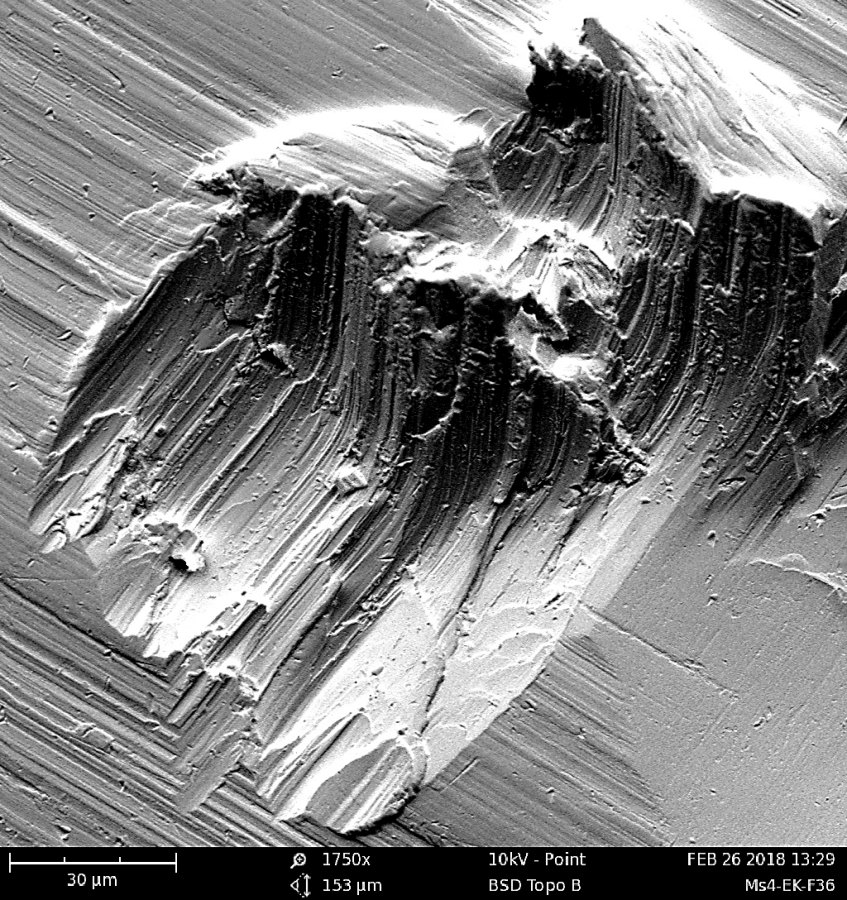

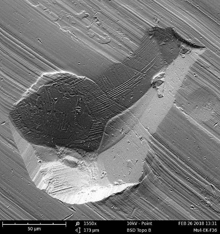
Fig. 12a to c: Cutting and non-cutting indentations of individual corundum grains, grain size 36, in the surface of a copper-zinc alloy at magnifications of a) 1,750, b) 860 and c) 1,550 (magnifications from the sample in Fig. 11)
A corresponding investigation with exactly the same setting of the blasting system was also carried out for the sample material aluminum and these samples also show similar impacts of the blasting grains (Fig. 13a to c). To illustrate the scattering and the range of impact craters, Figures 13a and b show two different areas of the surface of the same sample at a magnification of 260x. Figure 13c, on the other hand, is a further magnification (860x) from Figure 13b to clarify details.
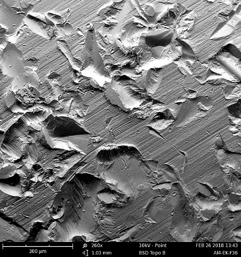
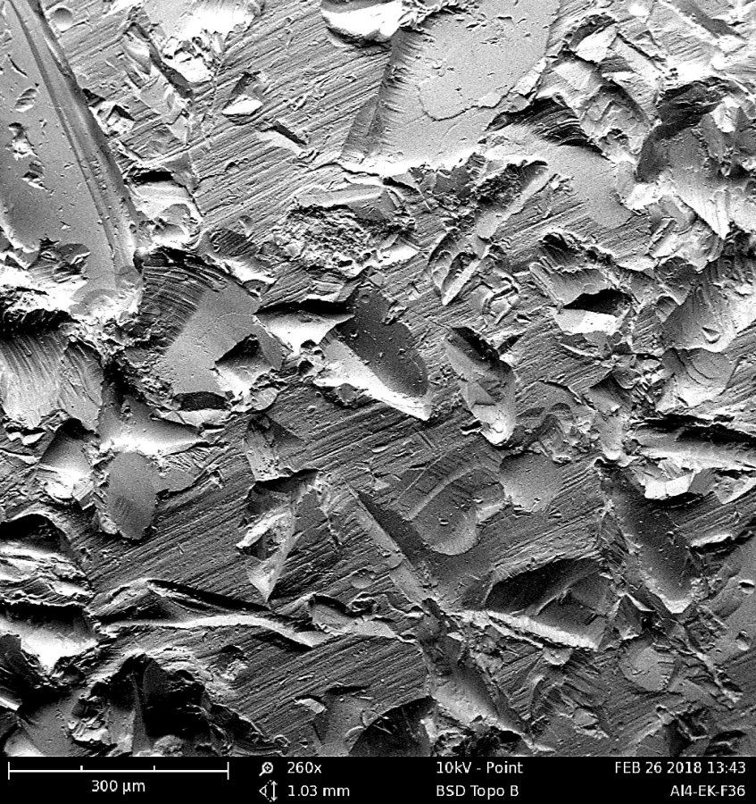
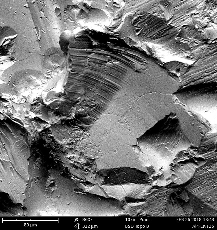
Fig. 13a to c: Impacts of individual corundum grains, grain size 36, into the surface of an aluminum alloy at magnifications of a) 260, b) 260 and c) 860
 sowie der Kupfer-Zink-Legierung (unten); Druckluft 6 bar, Abstand 50 mm, Winkel zur Oberfläche 45 °") Fig. 14a and b: Surfaces of the aluminum alloy (top) and the copper-zinc alloy (bottom) completely blasted with corundum, grain size 80; compressed air 6 bar, distance 50 mm, angle to the surface 45 °Thecompletely blasted samples are shown in Fig. 14a and b. Despite different colors due to the different alloys, the impression of the surfaces is similar, although the grain size is somewhat finer than in the previous images. Nevertheless, the surfaces differ when the roughness is measured. For example, the surface of the aluminum alloy has a roughness of Rz = 26.9 µm and that of the copper-zinc alloy only Rz = 22.1 µm.
Fig. 14a and b: Surfaces of the aluminum alloy (top) and the copper-zinc alloy (bottom) completely blasted with corundum, grain size 80; compressed air 6 bar, distance 50 mm, angle to the surface 45 °Thecompletely blasted samples are shown in Fig. 14a and b. Despite different colors due to the different alloys, the impression of the surfaces is similar, although the grain size is somewhat finer than in the previous images. Nevertheless, the surfaces differ when the roughness is measured. For example, the surface of the aluminum alloy has a roughness of Rz = 26.9 µm and that of the copper-zinc alloy only Rz = 22.1 µm.
The character of the surfaces is also different, as Rsk = 0.34 for aluminum and Rsk = -0.04 for brass, which means that the aluminum surface tends more towards peaks, while brass tends very slightly towards a plateau due to the negative sign. This is confirmed when comparing Rp and Rv: The peaks are comparatively higher in aluminum with Rp = 15.2 µm than the troughs with Rv = 11.7 µm deep and in brass this is almost
balanced.
The areas of the completely blasted surfaces shown in Figures 14a and b no longer show any free, non-blasted surface areas when enlarged (Fig. 15a to c). The impression and the idea of the nature of the surfaces is further improved if the images are viewed in the SEM with different detectors (acts like an illumination from the left or right).
The significance of such an observation becomes even clearer at higher magnification and the character of a surface can best be assessed in this way (Fig. 16a to c). Only in this way can individual topographical features be reliably identified when the "shadow" is compared due to the changing illumination from both sides.
These observations were also carried out for consolidation blasting with glass beads. Analogous to Figures 14a and b , Figures 17a and b show the samples blasted with the glass beads. The impression of the surfaces is finer on the one hand because it is a somewhat finer grain and on the other hand because, unlike corundum, the beads have no edges and therefore do not scatter the light as much for the photo. The very different character of the surfaces can only be clearly recognized and captured under magnification (Fig. 18a to b).
The "hammering" effect of the round beads is very clearly visible and the images also show that there is no metal removal. However, the round craters do not form a uniformly flat surface and after a certain number of impacts of the beads, they overlap. In contrast to machining with sharp-edged grain, such a surface will not be suitable as a basis for a coating, for example.
 Fig. 14bAsimilar, if not identical, picture emerges for the copper-zinc alloy material (Fig. 19a to c). This material is less ductile and flakes off at the edges of the impact craters to such an extent that small splinters and overlapping occur, which even lead to particles that could interfere with the use of the workpiece.
In contrast to the surfaces blasted with corundum, no typical roughness values can be specified for all surfaces blasted with glass beads. All values for Rz for both materials are between 13 and 20 µm and forRa between 2.1 and 3.4 µm, whereby the lower values for both dimensions and materials tend to apply to the larger beads. This also applies to the values of Rp and Rv and the character of the surfaces can be characterized with Rsk predominantly just above zero as rather pointed and clearly away from a plateau. Rsm is around 0.1 to 0.2 mm and the contact ratiosMr1 andMr2 are consistently between 9 and 12 % and between 85 and 91 % respectively. Therefore, none of these surfaces can be described or differentiated on the basis of the selected parameters.
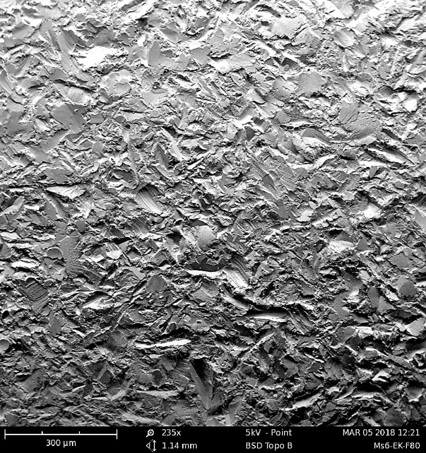

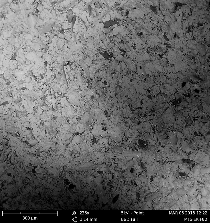
Fig. 15a to c: Surface of the copper-zinc alloy completely blasted with corundum, grain size 80 (235x magnification from Fig. 14b); a) illumination from top right, b) illumination from bottom left, c) material contrast due to the backscattered electrons

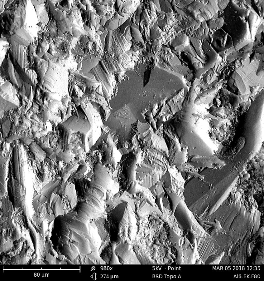
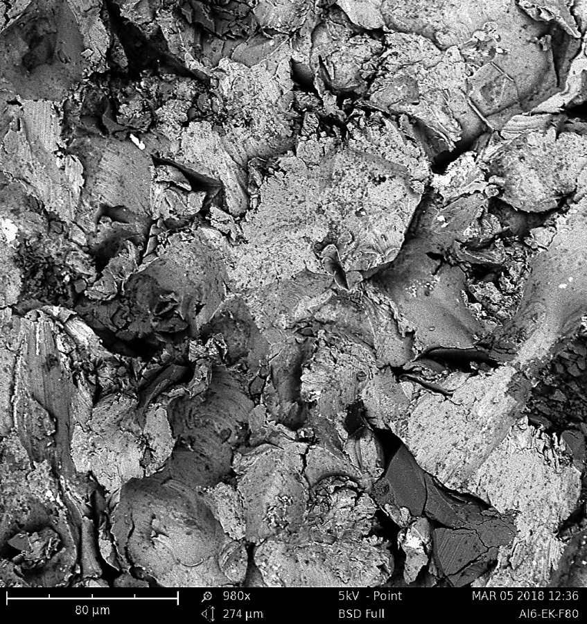
Fig. 16a to c: Surface of the aluminum alloy completely blasted with corundum, grain size 80 (980x magnification from Fig. 14a); a) illumination from top right, b) illumination from bottom left, c) material contrast due to the backscattered electrons
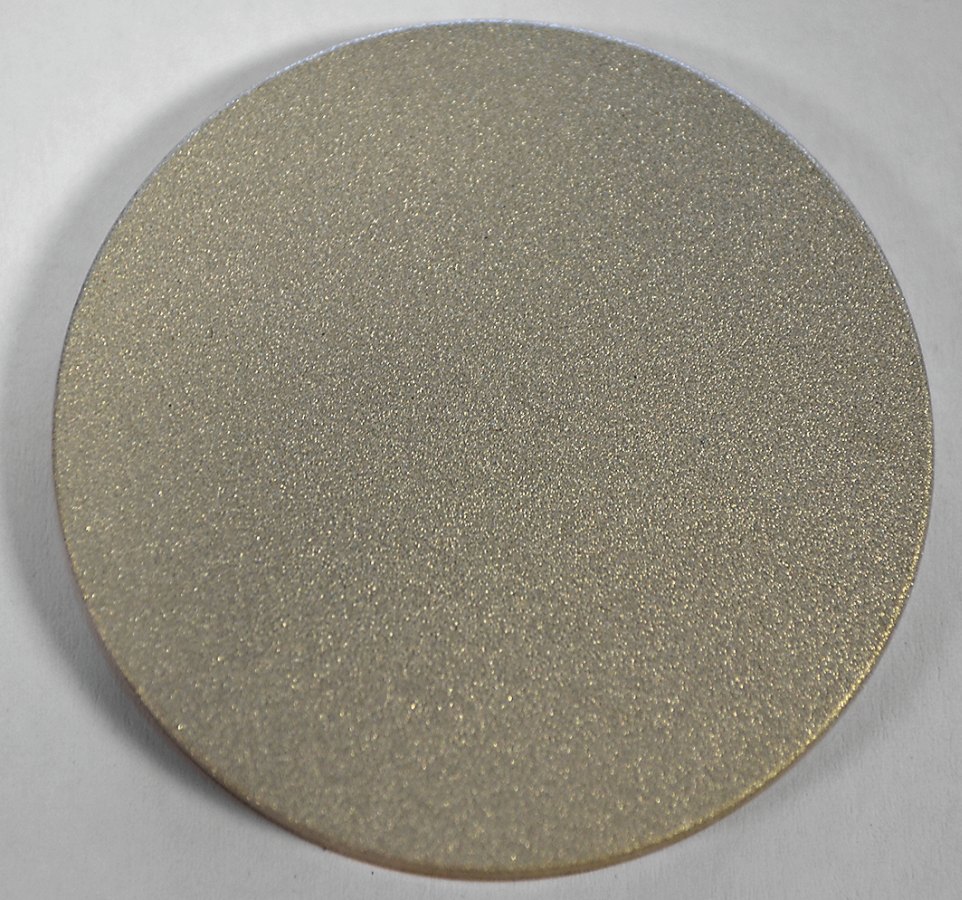
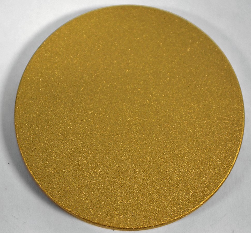
Fig. 17a and b: Complete with glass beads, average size 175 µm, blasted surfaces of the aluminum alloy (left) and the copper-zinc alloy (right); compressed air 6 bar, distance 50 mm, angle to the surface 45 °
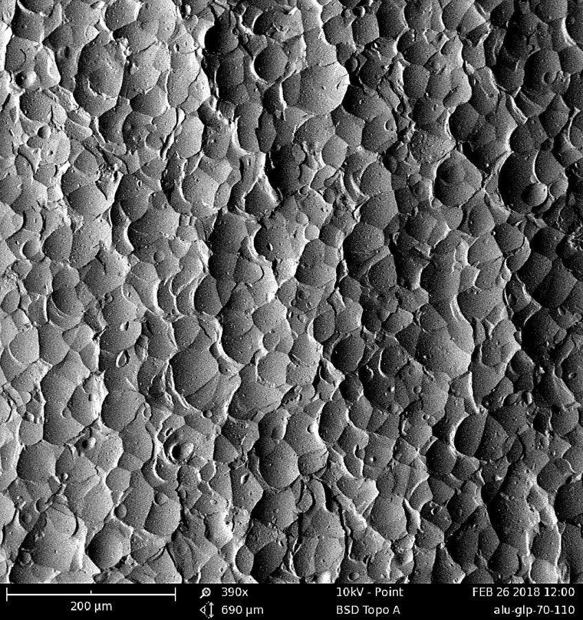
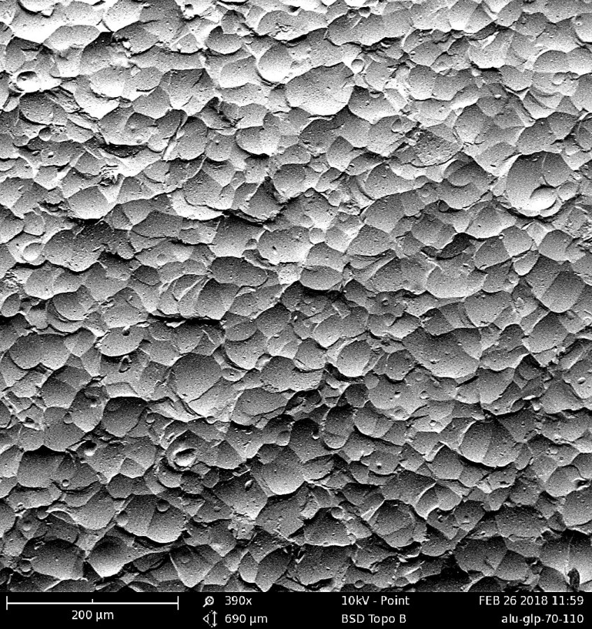
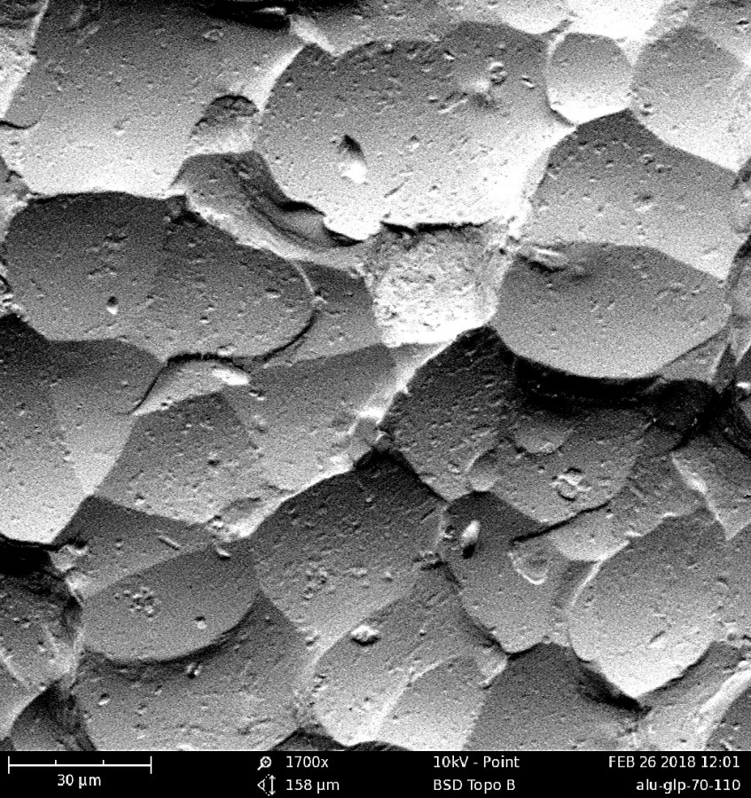
Fig. 18a to c: Complete with glass beads, average size 90 µm, blasted surface of the aluminum alloy (390x magnification from Fig. 17a); a) illumination from bottom left, b) illumination from top right, c) section from Fig. 17b, center, at 1,700x magnification


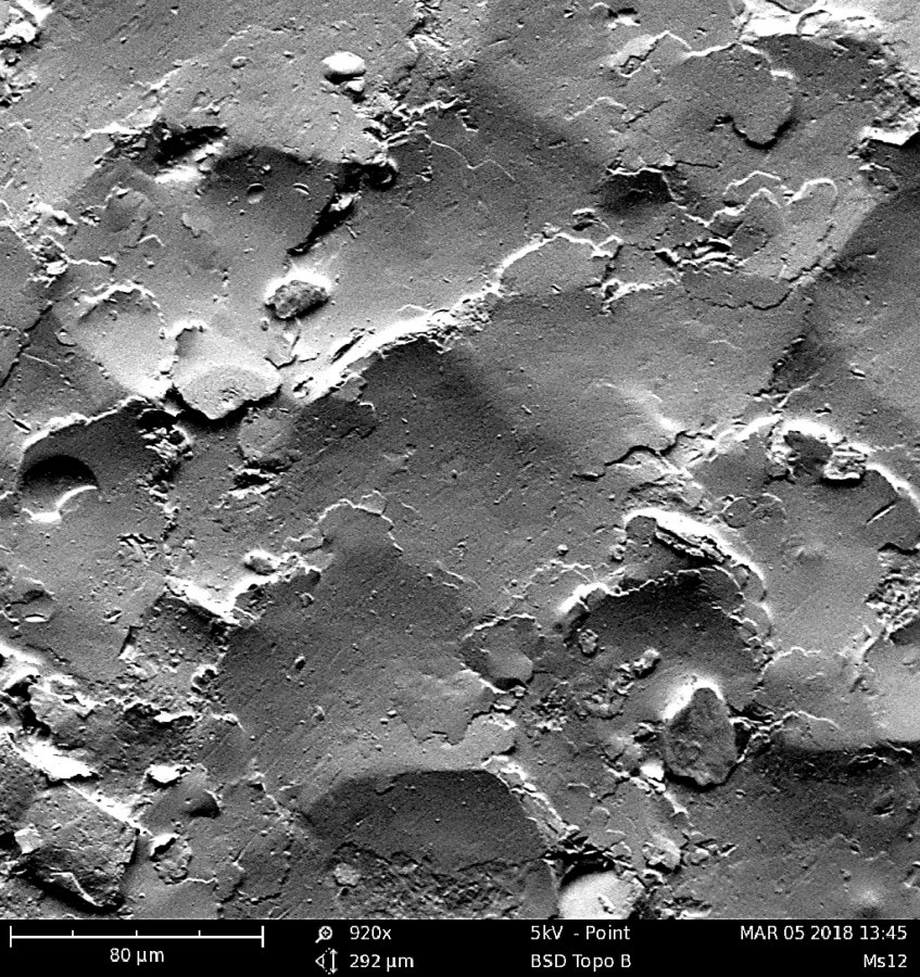
Fig. 19a to c: Complete with glass beads, average size 250 µm, blasted surface of the copper-zinc alloy (470x magnification from Fig. 17b); a) illumination from bottom left, b) illumination from top right, c) section from Fig. 19b, center, at 920x magnification
Test series 3
 Fig. 20: Device for blasting the samples in test series 3As asupplement, samples were blasted in a third test series as in test series 2 [11], whereby in this case only one spot was blasted in a fixed fixture (Fig. 20). This meant that the entire surface of the samples was also blasted, but with a focus in the center of the sample in order to be able to determine at the same time how intensively the samples are deformed by the various blasting media when blasted at one point.
Blasting media that were already treated in test series 2 are no longer discussed here, as they differ only slightly from the results. The blasting beads made of ceramic and the angular blasting media made of silicon carbide SiC were newly added. The new samples for the ceramic beads are shown in Figures 21a and b. The different behavior of the materials can be seen there under the same conditions. While the material is displaced over a larger area on the surface of the aluminum, this is not the case with the copper-zinc alloy and the ablation is concentrated more in the middle of the impinging beam.
The samples that were blasted with silicon carbide cannot be visually distinguished from those with corundum and are therefore not shown. However, the roughness differs for both the ceramic beads and the SiC. While the ceramic beads with Rz = 11.5 (aluminum) and Rz = 14.9 µm (copper-zinc alloy) produce a smoother surface than with the glass beads, the roughness values with Rz = 25.5 (aluminum) and Rz = 21.2 µm (copper-zinc alloy) for SiC are significantly higher than those produced with corundum. The other roughness values, which were listed and discussed in detail in the description of test series 2, also correspond to the detailed description of the character of the surfaces based on Rp, Rv or Rsk etc. in the case of the abrasives in test series 3.
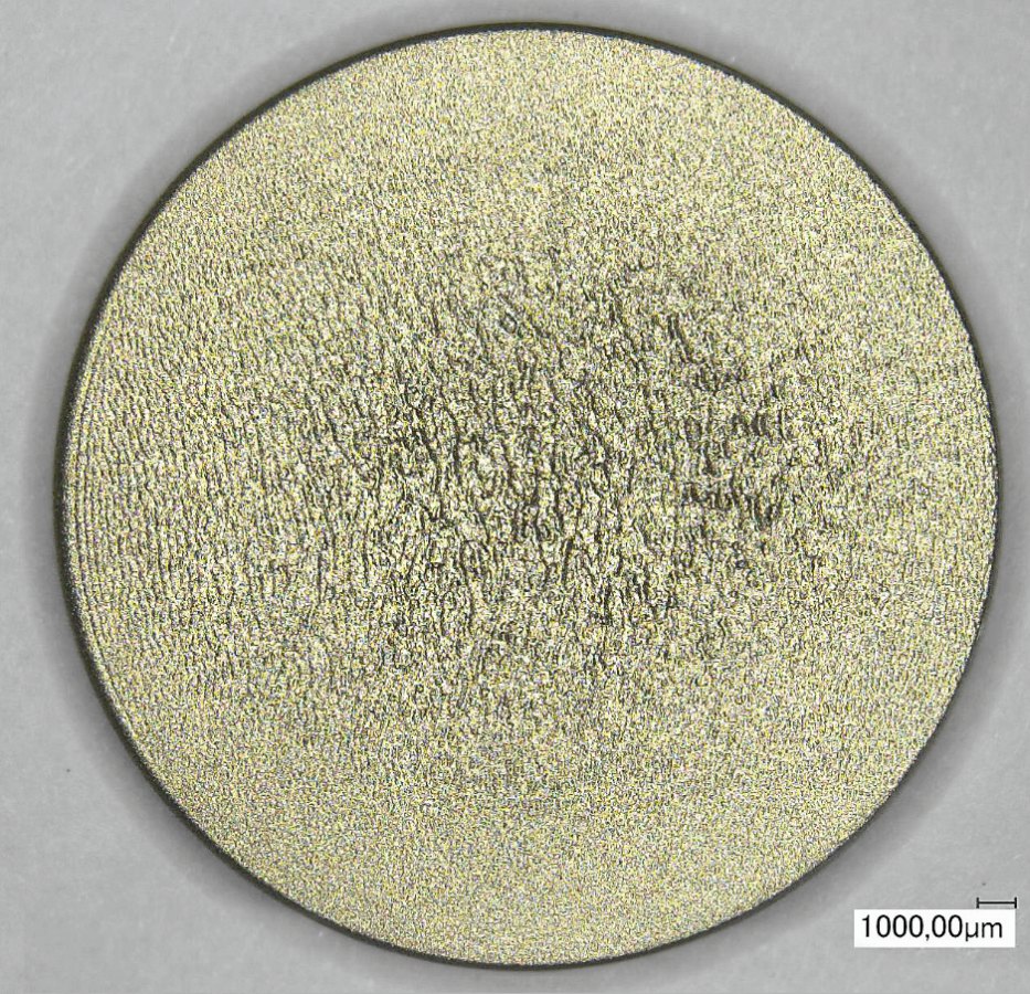

Fig. 21a and b: Completely with ceramic beads, average size 95 µm, blasted surfaces of the aluminum alloy (left) and the copper-zinc alloy (right); compressed air 4 bar, distance 50 mm, angle to the surface 45 °
Conclusion
Shot blasting is often regarded as a simple pre-treatment process for coatings and the like, and the process is just as often used without knowing in detail which surfaces are produced with which properties or which are actually needed for the respective applications. For series production, it is important to investigate this in detail and to understand the character of the surfaces. This can be done very well with the aid of measurement technology and documentation, and the present study is intended to contribute to this. Using several angular abrasives for roughening surfaces using the example of two non-ferrous metals and spherical abrasives for non-cutting treatment, it was possible to explain some of the relationships that contribute to a better understanding of this manufacturing process.
