This report is a summary of an Industrial Collective Research (IGF) project, which was carried out in cooperation between the Foundry Technology Department of the University of Applied Research in Aalen and the Electrochemistry/Electroplating Technology Department of the Research Institute for Precious Metals + Metal Chemistry (fem), Schwäbisch Gmünd. The project was initiated and supported by numerous companies from both the zinc die-casting and electroplating sectors due to unexplained cases of damage and problems with quality assurance in the process chain of manufacturing and electroplating zinc die-cast parts.
New findings on the mechanisms of defect formation were developed and a distinction was made between non-critical and defect-relevant process steps. A significant role of the interface between the casting material or casting skin and the copper plating in connection with the formation and temporary storage of hydrogen is indicated.
Results
The summary of the investigation results focuses on the main aspects in connection with the sample coating and the characterization of the electroplated samples by metallography, SEM, XRD and gas analysis. For casting-related aspects, please refer to further presentations and publications [5-9]; for further results, e.g. adhesion testing, computer tomography CT and corrosion tests as well as an overall presentation, see [10] and [11].
Characterization of uncoated samples
To summarize the SEM/EDX surface examinations on uncoated samples, it can be stated that pronounced flow marks can be seen in fields 3, 5 and 6 (most strongly in field 6). Release agent residues can be found in fields 1 + 2 (strongest in field 1). Release agent residues and residues of process solutions are more difficult to remove along gaps and indentations along the flow marks. This is therefore critical to the process. After changing the casting parameters, the flow marks were less pronounced, but still present in the problem areas (field 6).
Influence of the post-treatments
Fig. 3: SEM image of a Zn die-cast sample blasted with stainless steel, pointed, before (top) and after (bottom) electrochemical pre-treatment at exactly the same locationOfthe intended post-treatments (mechanical), the following variants were realized:
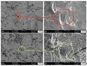
When blasting with plastic particles, loose Zn alloy particles that contaminate the blasting material are worked back into the surface; this can lead to problems with the coating. This also applies to blasting material made of pointed stainless steel particles that are pressed into the surface (see Fig. 3, highlighted in red). The stainless steel particles create an electrochemically heterogeneous surface with local element formation. This causes a significantly stronger attack during activation than with samples that have not been blasted with stainless steel. Cracks etc. are more clearly visible, the particles that have not been attacked are more prominent. The etching of the zinc surface is clearly visible in SEM examinations in a direct comparison between unblasted and blasted surfaces before and after pre-treatment (see Fig. 3, highlighted in green).
Testing the adhesion of the coating bond before and after the shock test
Figure 4 shows the shock test (200 °C/2 h, quenching in water) on uncoated samples; the following figures refer to coated samples. On the uncoated samples, only a few bubbles are visible due to swelling of the zinc (field 6), analogous to the blister test after casting.
Fig. 4: Uncoated samples (temperature shock, 200 °C/2 h, quenching in water RT), in groups of 3 "untreated/KS blasted/ES blasted", from left to right release agent 1-4, top row unaged, bottom row aged
Large areas of lifting can be seen, especially with release agents 1 and 2. The effect is somewhat stronger with aged samples. The lifting is most noticeable in the samples blasted with stainless steel and release agent 1. Individual sample fields are particularly critical, e.g. field 6, which is the furthest away from the sprue with a low wall thickness.
Fig. 5: Adhesive strength test on coated samples (not aged), in groups of 3 "untreated/KS blasted/ES blasted", from left to right release agent 1-4, top row CN-Cu, bottom row CN-free Cu
Fig. 7: General view and cross-section of a coated sample (release agent 1, aged, KS-blasted, CN-Cu)The area at the cross-section plane F is highly susceptible to pore formation during casting. The galvanic layers adhere to the swollen surface, the porous Zn bulk is swollen by thermal stress (see Fig. 7). The effect does not occur with uncoated samples, i.e. the pores are filled with gas, most likely hydrogen, during the electrochemical processes.
Fig. 6: Adhesion test on coated samples (aged), in groups of 3 "untreated/KS blasted/ES blasted", from left to right release agent 1-4, top row CN-Cu, bottom row CN-free Cu
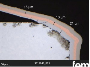
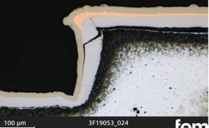
Fig. 8: General view of a coated sample (release agent 1, aged, ES-blasted, CN-Cu)The almost complete separation occurs below the casting skin (Fig. 9 left), i.e. it is not the electroplated layer that stands out, but the complete casting skin together with the layers above it. At point H, a series of pores can be seen between the casting skin and the center of the component (Fig. 9 right). However, the term "casting skin" is not entirely correct, because, as later phase investigations showed, this is a diffusion zone as a product of zinc and the first copper layer (Fig. 10). Casting skin residues, which may still be present after a grinding process, are transformed into a brittle layer by the mechanical/thermal stress and diffusion. This intermetallic phase detaches together with the coating. The brittle character of this phase is also shown by the cracking in Figure 11. The overall behavior is independent of the type of mechanical treatment.
There is a risk of misinterpretation in metallographic cross-section examinations, not only when assigning delaminated layers, but also on samples with perfect adhesion. If a zone appears as a dark intermediate layer, this is easily mistaken for a gap (see Fig. 17). The reason for the dark coloration is the change in the etching behavior of zinc and its stronger attack in contact with copper. It should also be noted that these samples show grinding grooves in the coating. There is no leveling. However, cracking can occur due to stresses introduced (see Fig. 17 right).
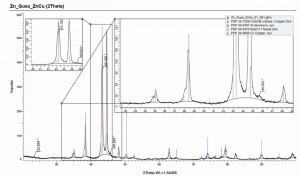
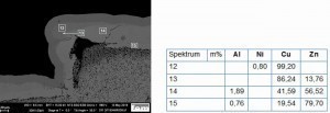
Fig. 9: Cross-section of a coated sample (release agent 1, aged, ES-blasted, CN-Cu), left: point G, right: point H according to the designation in Figure 8Thediffusion of zinc and copper leads to different brass phases, which can be distinguished by their color. The exact assignment of the phases g, α and e was carried out by EDX measurements in the SEM (see Fig. 13 and Fig. 14), according to the phase diagram in Figure 15. The g phase can also be detected on the underside of a delaminated layer after bubble formation by XRD examinations (see Fig. 16).
In principle, this means that the electroplated coating can withstand both thermal stress and quenching; the adhesive strength is guaranteed. However, the supply of hydrogen during the coating process can cause lifting/swelling in the bulk material or between the bulk and the casting skin. Differences depending on the casting skin structure and composition (influencing factors: casting parameters and release agent) are indicated. In order to investigate the influences of the electroplating process stages and the introduction of hydrogen in more detail, extensive analytical studies on the development of hydrogen as a secondary reaction and on the behavior of hydrogen in the structure or in the layers and at the interfaces would be necessary. In order to approach the problem, the method of hot gas extraction was modified as a potentially suitable procedure to at least obtain integral information about the hydrogen in the component.
Fig. 10: Cross-section examination of the ground sample 22-S
Fig. 11: Cross-section examination of zinc die-cast sample F-4, thermally deburred, item 3
Fig. 12: Cross-section of a sample at field 4 (ejector), release agent 1, untreated, aged for 6 weeks, blasted with stainless steel pointed, cyan. Cu
Fig. 13: SEM/EDX examination of a sample on field 4 (ejector), release agent 1, untreated, aged, blasted with stainless steel
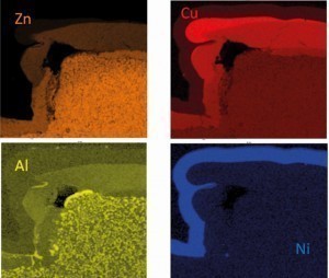
Fig. 14: Element mapping in SEM/EDX on a detail from Figure132)
2) Note: The aluminum found comes from the casting alloy
Fig. 15: Phase diagram in the copper-zinc system [12]
Fig. 16: XRD examination of the bubble underside of the delamination on sample 2-4S (Adolf Föhl GmbH, release agent 4, ground only, without ageing)
Fig. 17: Cross-sectional micrographs of a coated sample 2-4S (Föhl, release agent 4, ground only, without ageing)
Fig. 18: Investigation of hydrogen effusion at 250 °C after different pre-treatment and coating steps
Hydrogen determination
The test results to date indicate that, contrary to the widespread opinion that zinc cannot absorb significant amounts of hydrogen, hydrogen loading of the Zn die casting alloy does occur. The usual hydrogen analysis using hot extraction (determination of the total content) is not normally carried out on zinc and Zn alloys due to the low vapor pressure of zinc. An attempt has now been made to drive the hydrogen out of the material at lower temperatures < 400 °C and to determine it analytically. The aim of these previously unplanned investigations was to derive conclusions about the hydrogen input from the pre-treatment and the coating.
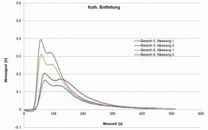
Fig. 19: Measurement signals of the hot gas extraction on cathodically degreased samples, not coated
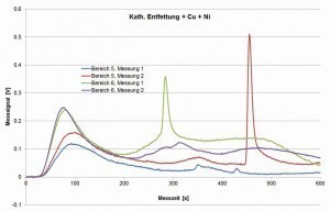
Fig. 20: Measurement signals of the hot gas extraction on cathodically degreased samples, coated with copper and nickel
For this purpose, areas 5 and 6 of the casting sample geometry (area 5 with 3 mm wall thickness, area 6 with 0.8 mm) were selected as examples, separated and analyzed as duplicate samples. The temperature of 250 °C was chosen arbitrarily and may have an influence on the rate of effusion and the amount of hydrogen analyzed.
The results of these orienting investigations can be summarized as follows (see also Fig. 18):
While the untreated casting samples contain almost no hydrogen, hydrogen is clearly detectable after cathodic degreasing, in varying quantities in different areas of the casting samples (step plates with varying thickness). After anodic degreasing, no increase is recognizable, only after galvanic coating, whereby copper and nickel have different effects.
The exact mechanisms are still unclear. The original measurement curves of the signal (sensor for the thermal conductivity in the gas flow, measured values in volts) indicate that the effusion of hydrogen does not occur uniformly, but possibly erratically depending on an "opening" or accessibility of the area in which hydrogen was stored in the material (see Fig. 19 and Fig. 20). After optimizing this method as part of a follow-up project, this could be a means of better understanding the hydrogen input, its influencing variables and the storage mechanism in order to derive possibilities for avoiding the associated error pattern.
Fig. 21: Cross-section investigations on samples from the cyanide (left) and cyanide-free electrolyte (right), overview unetched
Use of a cyanide-free copper electrolyte
When using a cyanide-free copper electrolyte instead of cyanide copper plating, the plating conditions were adapted to the requirements of this electrolyte. The solution only allows lower applicable current densities, so that the process time had to be extended (see Table 1). The cross-section shows structural differences between the copper layers (see Fig. 22). Copper deposited from the cyanide-free solution is finer-grained and therefore has a higher hardness (see Tab. 2). However, this is not a permanent hardness. After recrystallization by heat treatment (30 min at 200 °C), the hardness drops to 103 HV.
Fig. 22: Cross-section tests on samples from the cyanide (left) and cyanide-free electrolyte (right), detail with Cu structure
The behavior of the cyanide-free coated samples after the adhesion test (temperature shock, 200 °C/2 h, quenching in water RT) does not differ significantly from the cyanide-coated samples. Bubble formation with delamination below the casting skin or zinc diffusion phase occurs, as the cross-sectional examinations show (Fig. 23). Fig. 23: Cross-section of a cyanide-free coated sample after shock test (release agent 1, not aged, blasted with stainless steel particles)
| Sample designation |
Individual values HV 0.005 |
Mean value HV0.005 |
|
Sample E Chemopur
Cu Layer hardness cyanide-free electrolyte |
301 |
296 |
280 |
296 |
276 |
290 |
| 280 |
290 |
|
|
|
285 |
|
Sample G Cuprum 10
Cu Layer hardness cyanide electrolyte |
110 |
96 |
107 |
104 |
105 |
104 |
| 107 |
110 |
|
|
|
108 |
Table 2: Hardness measurement on Cu interlayers from cyanide and cyanide-free electrolytes
Conclusion
The resulting quality of coated zinc die-cast parts depends on the entire process chain. In the first step, this includes the casting quality, i.e. the lowest possible number of pores and voids, good alloy homogeneity and the lowest possible release agent residues or the use of suitable release agents. The type of post-treatment, i.e. the use of blasting processes, grinding or polishing, must be adapted to the product and must not leave any residues on the surfaces (blasting material, polishing pastes) or these residues must be removed without delay.
In the electroplating process, the pre-treatment steps, rinsing processes, coating processes and drying must be applied correctly and professionally. The layer thicknesses and the layer structure must be applied correctly. It is necessary to keep an eye on the condition of the electrolytes, i.e. their bath load, possible impurities, concentrations of the active components and the additive system. The design of the components must be adapted to the casting process and follow the principles of electroplating-compatible design.
Special challenges that have not yet been conclusively answered are the phase formation in the layer system with zinc and the hydrogen loading of the zinc die casting alloy. Contrary to previous opinion that zinc cannot absorb significant amounts of hydrogen, storage does take place. The mechanisms for this are to be investigated in a follow-up project. The activity of hydrogen, especially at elevated temperatures, can lead to blistering and material damage. Delamination takes place within brittle zinc phases, which form relatively quickly together with the copper layer due to zinc diffusion.
Knowledge of the causes of coating defects in zinc alloys makes it possible to significantly minimize the number of rejected parts. Interrupting the extensive value chain from casting to the end product at an early stage significantly improves resource efficiency and reduces the mutual apportioning of blame between the caster and coater, contributing to the economic success of all parties involved.
Acknowledgements
The project was generously and constructively supported by the project support committee in the form of material and consulting services. Many thanks to the companies involved:
Adolf Föhl GmbH & Co.
Artur Monse GmbH & Co. KG
Chem-Trend Deutschland GmbH
Chemopur Brand GmbH
Dr.-Ing. Max Schlötter GmbH+Co.KG
FEIX DRUCKGUSS GmbH & Co. KG
Geiger + Co. lubricant chemistry GmbH
Grillo Werke AG
HDO Druckguß- und Oberflächentechnik GmbH
HZD GmbH & Co. KG
Engineering office Ulrich Bingel
Moosbach & Kanne GmbH
Oskar Frech GmbH + Co. KG
Rieger Metallveredlung GmbH & Co. KG
Rosenberger Hochfrequenztechnik GmbH & Co. KG
SurTec Group
The IGF project 19483 N of the Forschungsvereinigung Edelmetalle und Metallchemie e. V. in cooperation with Forschungsvereinigung Gießereitechnik e. V. was funded via the AiF as part of the program for the promotion of industrial joint research (IGF) by the Federal Ministry for Economic Affairs and Energy on the basis of a resolution of the German Bundestag.
Literature
[1] Pfeifer-Schäller, I.; Klein, F.: Defects in the surface finishing of zinc die castings, 23rd Aalen Foundry Symposium (2002), Lecture 10
[3] Volk, P.: Finding the right coating for every zinc die-cast component; MM MaschinenMarkt 34(2013), 32
[4] Schwarz, G.: Cleaning brass and zinc die castings before electroplating; Galvanotechnik 73(1982)7, 708
[5] Blumenberg, A.: The influence of pre-treatment on the appearance and structure of electroplated zinc layers, 20th Leipzig Technical Seminar, DGO, Leipzig (2013)
[6] Mangos, C.: First results of the research project "Influence of aging, manufacturing and post-treatment processes on the galvanic coatability of zinc die castings"; 18th International German Die Casting Day, 15.01.2018, Euroguss Messe Nürnberg
[7] Mangos, C.: Influence of ageing, manufacturing and post-treatment processes on the galvanic coatability of zinc die castings; Aalener Gießerei Kolloquium, 17.05.2018, Aalen University of Applied Sciences
[8] Kansy, A.: Latest findings on the research project "Electroplating of zinc die castings", Aalen Foundry Colloquium, 09.05.2019, Aalen University of Applied Sciences
[9] Mangos, C.; Kallien, L.; Kansy, A.; Freudenberger, R.; Pfund, A.; Funk, M.: Influence of ageing, manufacturing and post-treatment processes on the galvanic coatability of zinc die castings, To be published in Giesserei-Special Forschung und Innovation, 2(2020)
[10] Pfund, A.; Funk, M.; Freudenberger, R.; Kansy, A.; Mangos, C.; Kallien, L.: Aktuelle Ergebnisse zum Einfluss von Herstellungs- und Beschichtungsprozessen bei der Galvanisierung von Zinkdruckguss; Tagungsband: GfKORR-Jahrestagung 2019 in Frankfurt a. M. "Nachhaltiger Korrosionsschutz mit Zink", pp. 121-134, Publisher: GfKORR-Gesellschaft für Korrosionsschutz e.V.
[11] IGF project no. 19483 N, final report 2020, available from the Forschungsvereinigung Forschungsinstitut Edelmetalle + Metallchemie (fem), Schwäbisch Gmünd
[12] Massalski, T.B.: Binary Alloy Phase Diagrams, American Society for Metals, Metals Park, OH, 1986
 Fig. 4: Uncoated samples (temperature shock, 200 °C/2 h, quenching in water RT), in groups of 3 "untreated/KS blasted/ES blasted", from left to right release agent 1-4, top row unaged, bottom row aged
 Fig. 5: Adhesive strength test on coated samples (not aged), in groups of 3 "untreated/KS blasted/ES blasted", from left to right release agent 1-4, top row CN-Cu, bottom row CN-free Cu
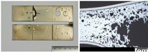 Fig. 7: General view and cross-section of a coated sample (release agent 1, aged, KS-blasted, CN-Cu)The area at the cross-section plane F is highly susceptible to pore formation during casting. The galvanic layers adhere to the swollen surface, the porous Zn bulk is swollen by thermal stress (see Fig. 7). The effect does not occur with uncoated samples, i.e. the pores are filled with gas, most likely hydrogen, during the electrochemical processes.
 Fig. 6: Adhesion test on coated samples (aged), in groups of 3 "untreated/KS blasted/ES blasted", from left to right release agent 1-4, top row CN-Cu, bottom row CN-free Cu
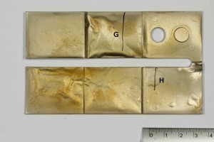 Fig. 8: General view of a coated sample (release agent 1, aged, ES-blasted, CN-Cu)The almost complete separation occurs below the casting skin (Fig. 9 left), i.e. it is not the electroplated layer that stands out, but the complete casting skin together with the layers above it. At point H, a series of pores can be seen between the casting skin and the center of the component (Fig. 9 right). However, the term "casting skin" is not entirely correct, because, as later phase investigations showed, this is a diffusion zone as a product of zinc and the first copper layer (Fig. 10). Casting skin residues, which may still be present after a grinding process, are transformed into a brittle layer by the mechanical/thermal stress and diffusion. This intermetallic phase detaches together with the coating. The brittle character of this phase is also shown by the cracking in Figure 11. The overall behavior is independent of the type of mechanical treatment.
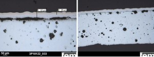 Fig. 9: Cross-section of a coated sample (release agent 1, aged, ES-blasted, CN-Cu), left: point G, right: point H according to the designation in Figure 8Thediffusion of zinc and copper leads to different brass phases, which can be distinguished by their color. The exact assignment of the phases g, α and e was carried out by EDX measurements in the SEM (see Fig. 13 and Fig. 14), according to the phase diagram in Figure 15. The g phase can also be detected on the underside of a delaminated layer after bubble formation by XRD examinations (see Fig. 16).
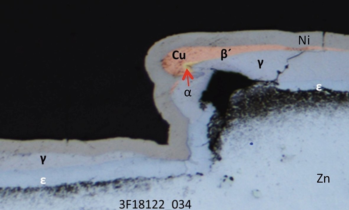 Fig. 12: Cross-section of a sample at field 4 (ejector), release agent 1, untreated, aged for 6 weeks, blasted with stainless steel pointed, cyan. Cu
 Fig. 17: Cross-sectional micrographs of a coated sample 2-4S (Föhl, release agent 4, ground only, without ageing)
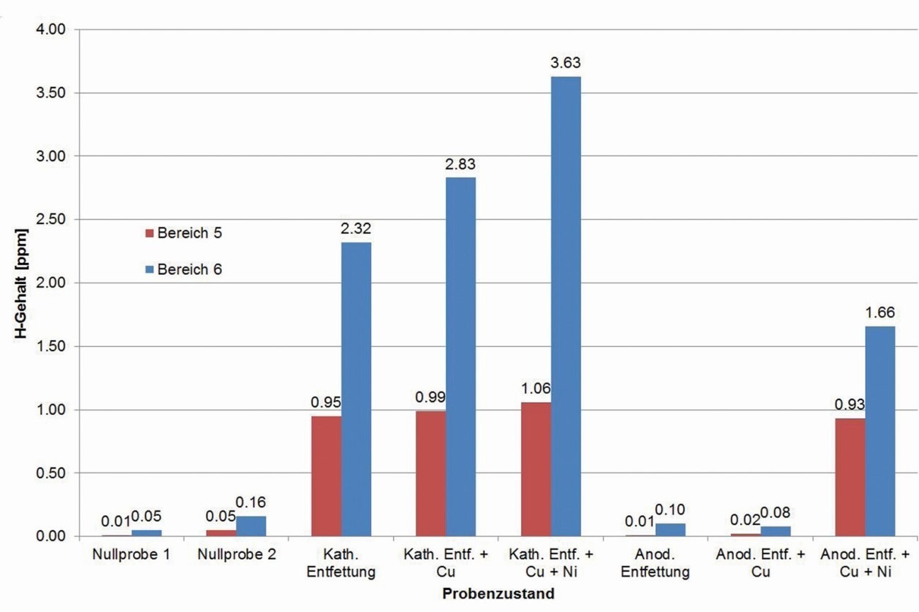 Fig. 18: Investigation of hydrogen effusion at 250 °C after different pre-treatment and coating steps
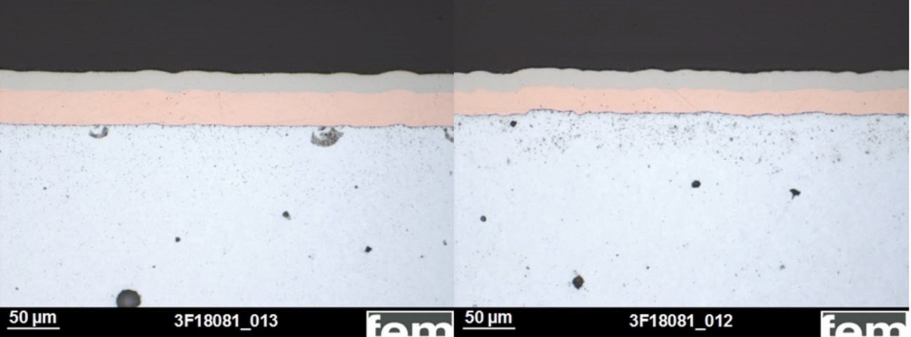 Fig. 21: Cross-section investigations on samples from the cyanide (left) and cyanide-free electrolyte (right), overview unetched
 Fig. 22: Cross-section tests on samples from the cyanide (left) and cyanide-free electrolyte (right), detail with Cu structure
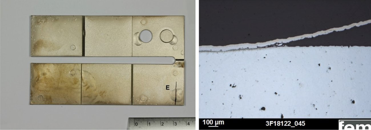 Fig. 23: Cross-section of a cyanide-free coated sample after shock test (release agent 1, not aged, blasted with stainless steel particles)


![Abb. 15: Phasendiagramm im System Kupfer-Zink [12] GT5 20 fem 15](/images/stories/Redaktion_GT/Online-Artikel/thumbnails/thumb_GT5-20_fem-15.jpg)
