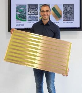
The Steinach-based company Becker & Müller focuses on custom-made products, prototypes and samples in the production of printed circuit boards. This includes customer-specific PCBs in oversizes of up to 427 x 884 mm.
 Janik BeckerContraryto the general trend towards miniaturization in electronics, there are also applications that explicitly require large PCB sizes. Examples of such 'big size PCBs' include medical technology, power generation and telecommunications. Flexible oversized PCBs are used in industrial electronics, aerospace and military technology, among others. In addition, these special sizes offer cost and safety advantages wherever the combination of separate rigid PCBs can be replaced by a single unit.
However, PCBs of these dimensions push fully automated processes to their limits - they require additional manual production steps and special handling. Although competitors, mostly from the Far East, also manufacture PCBs of these sizes, they only do so in very large quantities. As a prototype manufacturer, Becker & Müller makes use of this decisive advantage and produces from a batch size of one.
Special PCBs require special processes
Oversized PCBs pose technical challenges for production. On the one hand, the sheer dimensions of the panels exceed the capacities of conventional processing machines. These are designed for a maximum of 457 x 610 mm and simply offer too little space in the longitudinal or Y direction for the oversized panels measuring 457 x 914 mm. This mainly affects CNC machines and direct imagesetters, whose working areas therefore had to be extended.
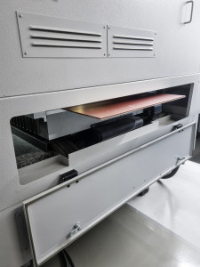
The first step in the implementation was to accommodate the longer panels on the machine tables. By using vacuum tables in combination with specially developed adapters, it was possible to provide a comparatively simple solution and at the same time avoid having to replace the tables. As the size of the machines is not designed for the adapted machine tables, these threaten to collide with the machine wall at maximum travel in the Y direction. A spatial extension of the machines is absolutely necessary, and the corresponding solution is also kept as simple as possible here. Both the CNC machines used and the direct imagesetters are already equipped with service flaps by the manufacturer to allow access to the machine tables from the rear for maintenance. Replacing these service flaps with specially manufactured housing extensions makes it possible, in theory, to extend the space available in the Y-direction to any size while retaining the original quality and safety aspects.
Mechanical precision through register marks
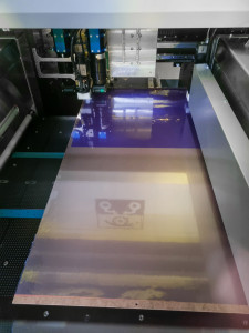
 The exposure of the panels is segmented - process reliability and quality are already taken into account in the DFM processTheextension of the actual machining areas of the machines - i.e. the travel paths of the tool spindle or exposure head - cannot be easily realized technically. Modifying guideways, linear motors, controls, etc. was not an option. As an alternative solution, Becker & Müller decided to separate the respective production steps in the middle of the Y-direction and to process the panels separately from two sides. This has an impact on the creation of the data in the design-for-manufacturing process (DFM). The production data is halved for each layer, and this segmentation of the panels doubles numerous work steps. In conjunction with the enormous dimensions, this places increased demands on process reliability. The implementation of registration holes and fiducials is intended to ensure mechanical precision and electrical functionality - particularly with regard to a seamless transition of the layout in the middle of the panel.
Precision is required when inserting the registration holes in the first production step, DK drilling. During the exposure process, these holes are recognized as (panel) registration marks based on the camera registration and are used to structure the layout and position the fiducials. These photo-structured fiducials are positioned both globally and locally. Fiducials are used for camera registration in subsequent processes, where they are used to determine the position of the individual PCBs on the panel and to compensate for stretching and compression. Global fiducials are positioned around individual PCBs and are used for subsequent finishing. Local fiducials are positioned around particularly critical (partial) areas of the individual PCBs and increase the positioning accuracy of NDK drill holes, for example. This process makes it possible to maintain position tolerances of < 20 μm between the drill hole and conductor pattern as well as a 'line and space' of 75 μm.
Surface treatments reach their capacity limits
Due to the sheer size of the panels, handling between individual process steps and loading the machines and systems is largely carried out manually. In order to reduce the probability of errors to a minimum, Becker & Müller uses the poka-yoke method (i.e. avoiding unintentional errors). By segmenting the data, the panels pass through two to four separate processing steps in the mechanical and phototechnical process steps, in which they have to be positioned differently in the machines. The special arrangement of registration holes and fiducials ensures that the machine recognizes an incorrectly inserted panel and does not process it accordingly.
 Opening the service flap of the CNC drilling and milling machine creates capacity for the extended dimensions of the panels. Longer panels do not pose a problem for horizontal throughfeed systems - such as those used for wet-chemical treatment and the spraying of solder resist. However, they require more effort during handling. However, this does not apply to the galvanic copper build-up and the application of the final surface, as these processes do not take place horizontally, but vertically in basins. Where the treatment tanks do not have the capacity to immerse the panels either lengthwise or crosswise, the panels are again segmented. The process is split in two and carried out separately for the front and rear parts of the panel. Tests have shown that the entire surface of the panel can be coated using this technique. However, if the design allows it, it is advisable to avoid coating the center of the panel during the DFM process. Special designs for handling, transportation and machining have been developed for flex PCBs.
Automated intermediate inspections are only possible to a limited extent
Continuous inspection and testing processes accompany production. Intermediate visual inspections can be carried out without any problems and are carried out to a greater extent immediately after all process steps. The inspection rate is 100%. Technically and visually flawless panels are released for further processing.
Automated and mechanical intermediate inspections, on the other hand, are only possible to a limited extent. There is no way to technically expand the capacity of AOI (Automatic Optical Inspection) and E-Tester. Therefore, depending on the complexity of the circuits, the electronic check is carried out manually.
A solution has also been found for testing mechanical properties such as compliance with position tolerances of the drilling and conductor pattern. By redesigning the machine table of the CNC video measuring microscope used and designing a special adapter for its extension, the measurements can be carried out and documented in a segmented but automated manner as usual.


