
Thermal management in printed circuit boards and assemblies is an ever-increasing challenge: whether LED applications with high light output, HF technology or power electronics - better heat transfer and cooling are increasingly in demand
The aim of thermal management in a printed circuit board or electronic assembly is to get the heat away from the heat-generating components and dissipate it to the outside. Improved heat transfer reduces the risk of thermal overload of active components and is often a decisive factor in meeting the product's service life requirements.
The following technologies at PCB level improve heat dissipation:
- Metal core technology
- Copper pillar technology
- Copper coin technology
Metal core technology (MCPCB)
A simple way to greatly improve heat dissipation is to use other thermally conductive di-electric materials for the PCB instead of the standard material for multilayer PCBs (FR4) and to laminate these to a metallic base (metal core PCB). A PCB constructed in this way has a significantly higher thermal performance. MCPCBs use di-electric heat conducting foils between the copper layers, which enables heat dissipation to the metal core, to the metal base substrate and thus also from the components.
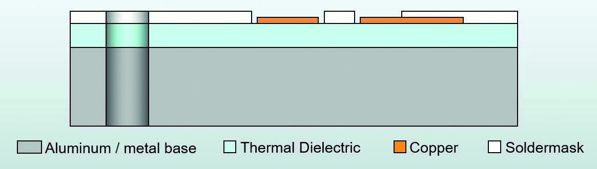 Fig. 1: Single-sided MCPCB (top copper layer)
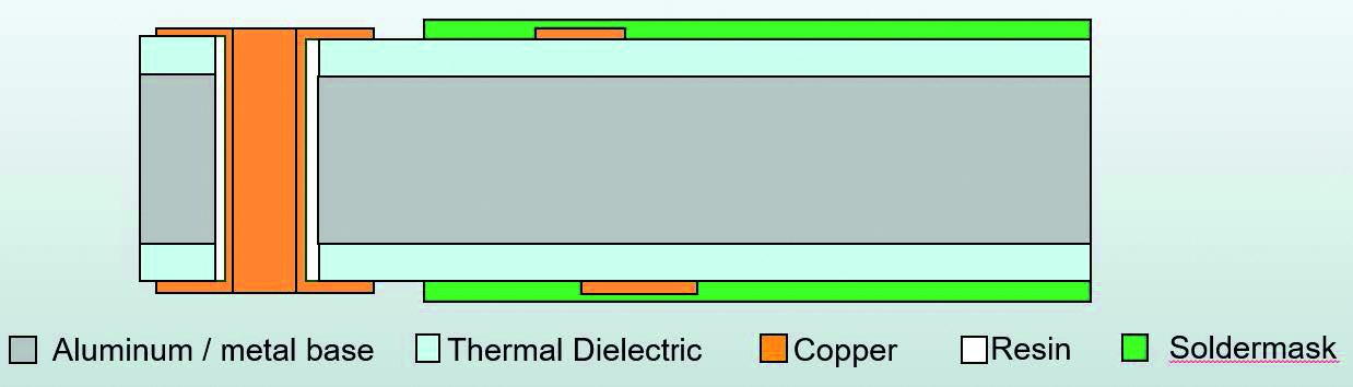 Fig. 2: Double-sided MCPCB (top & bottom copper layer)
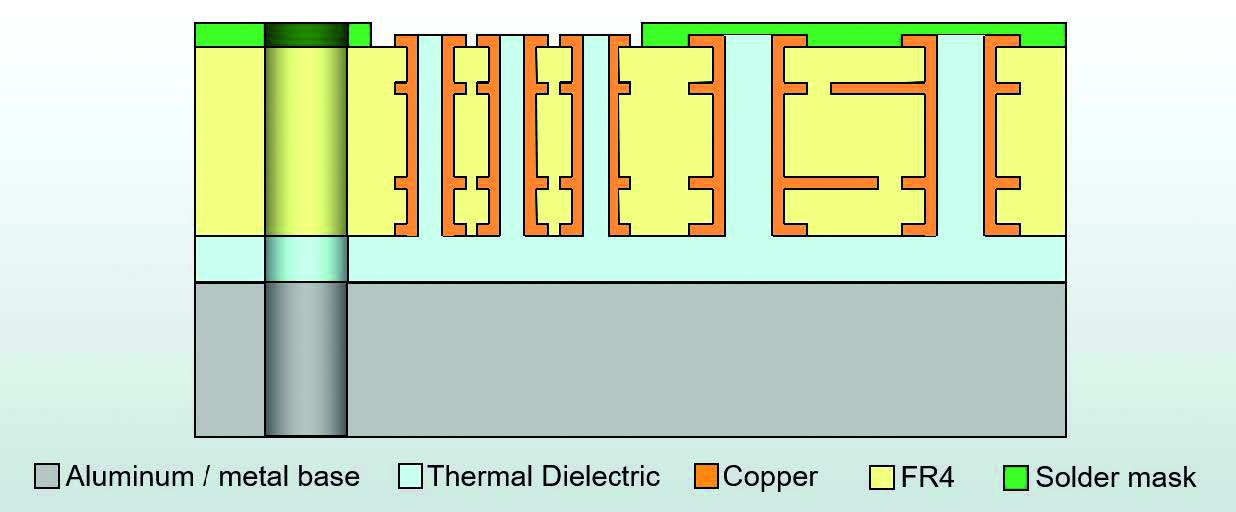 Fig. 3: Multilayer MCPCB (+4 layers FR4)
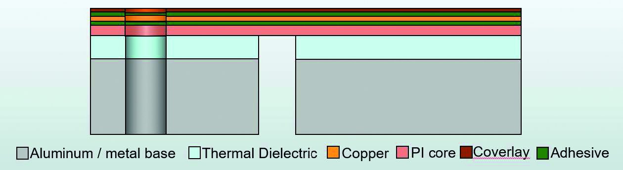 Fig. 4: Rigid-flex MCPCB (double-sided flex layer)
MCPCBs can be realized with a single copper layer(Fig. 1) over a metallic base substrate (aluminium, copper or steel) or with a double-sided copper layer structure (top & bottom)(Fig. 2) or can also be constructed as a multilayer(Fig. 3). Rigid-flex structures can also be realized with metal base substrates(Fig. 4).
Figure 5 below shows a 2-layer MCPCB structure in which the heat transfer from the component on the top side through the structure to the metal substrate is shown. With this structure, a thermal conductivity of up to 12 W/mK can be achieved.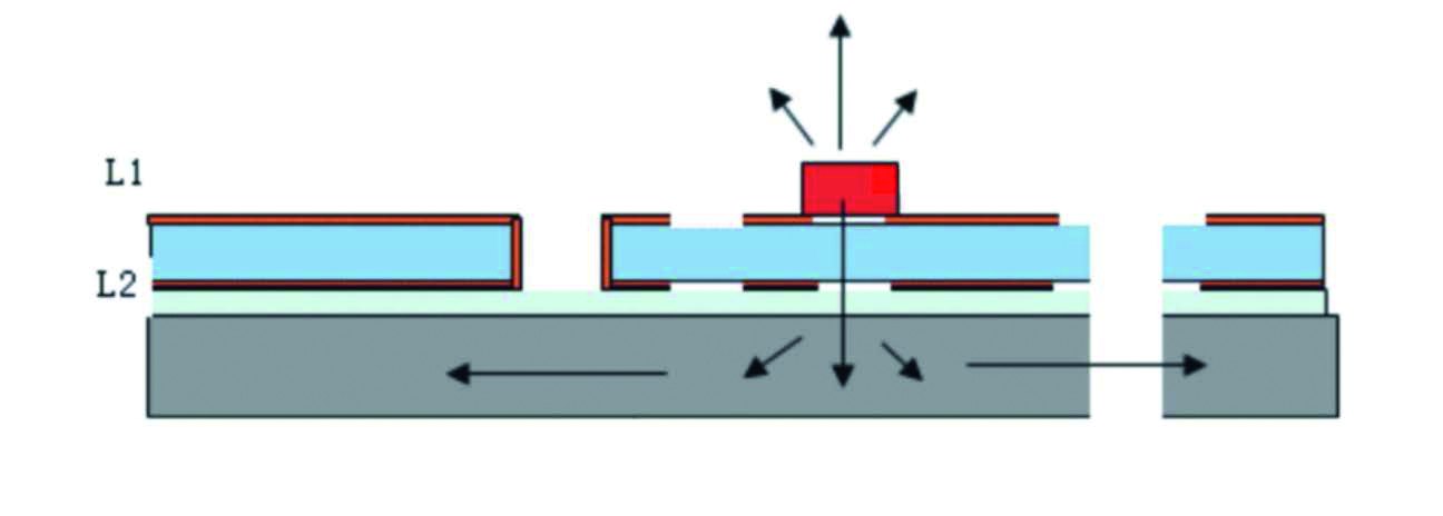 Fig. 5: Double-sided MCPCB with top and bottom layer on top
If a higher heat transfer is required, the use of copper column technology or copper coin technology is recommended.
Copper column technology
The patented copper column technology is ideal for connecting the base substrate directly to the heat source and utilizing the full thermal conductivity of the copper base substrate (approx. 400 W/mK). With this technique, columns of copper are formed from the base substrate.
This form of heat dissipation is suitable for 1- or 2-layer PCBs. The copper pillar termination is formed at the same level as the printed circuit board on top. Power and logic circuits can also be electrically connected here - so a direct connection is possible in every respect.
The copper base substrate can also be split and electrically separated with epoxy. This means that copper pillar technology can also be used for the construction of high-current applications. This electrical separation means that various high-current potentials with a connected logic part can be realized on one PCB.
Such solutions are currently and in the future particularly needed for e-mobility, where very high power has to be accommodated in a very small installation space(Fig. 6, 7 and 8).
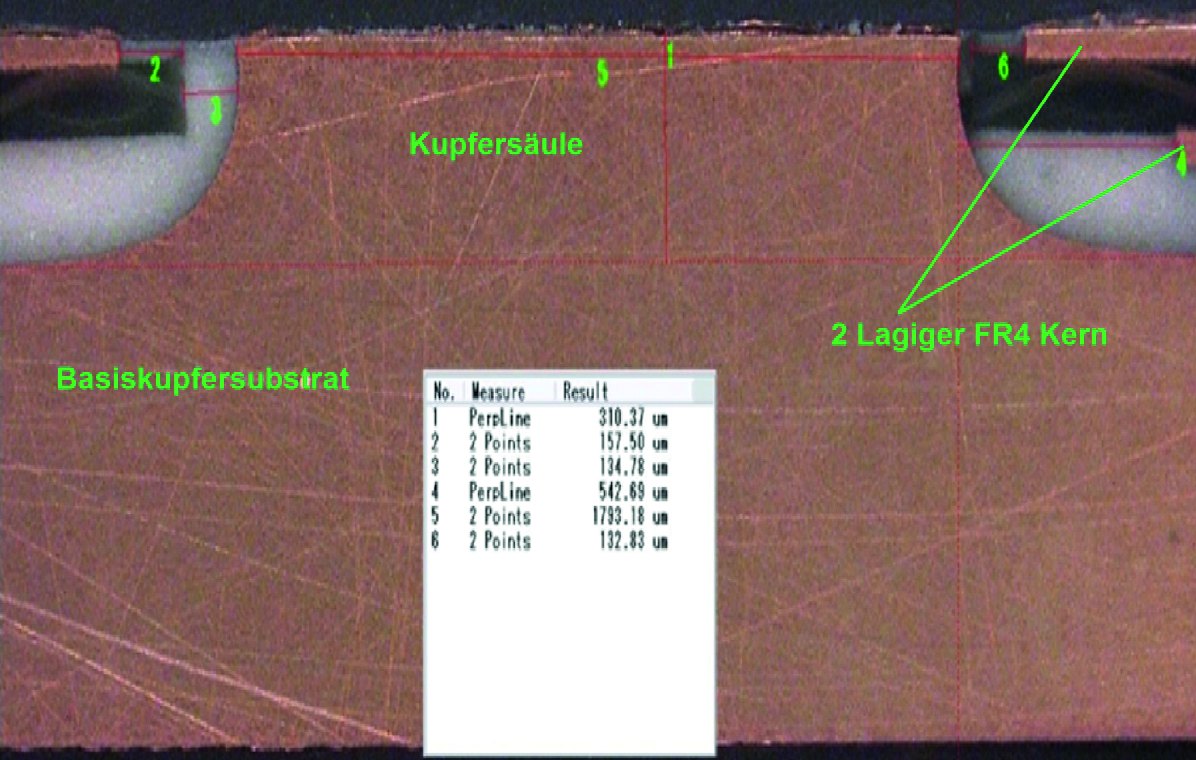 Fig. 6: Copper column technology
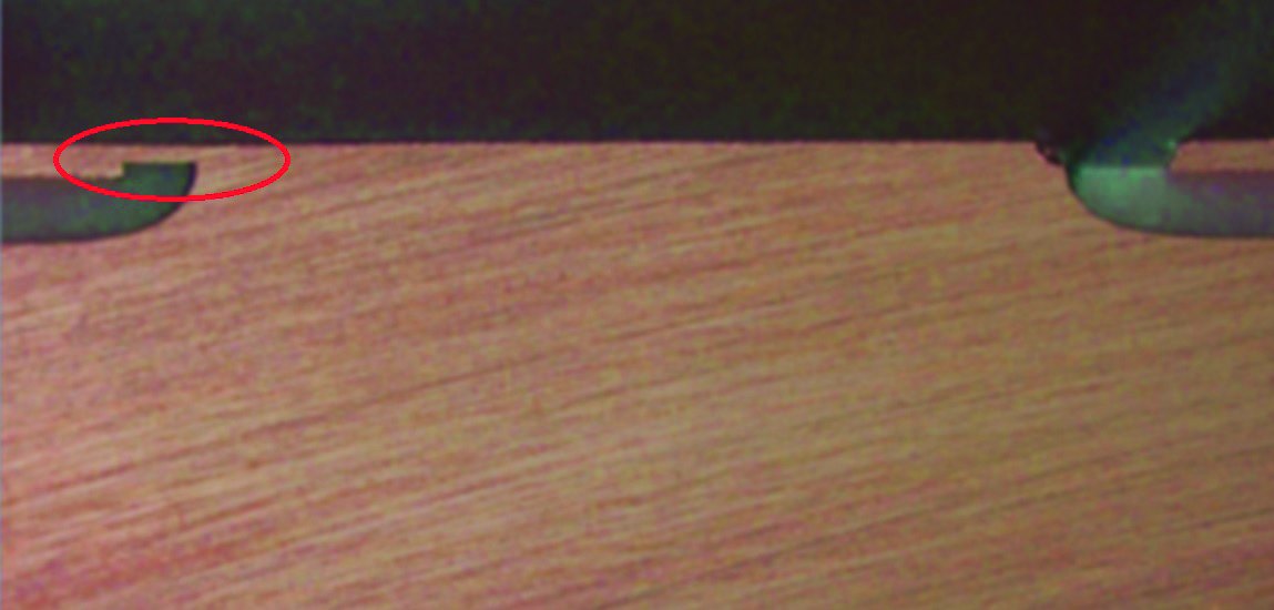 Fig. 7: Copper column with connection to logic section
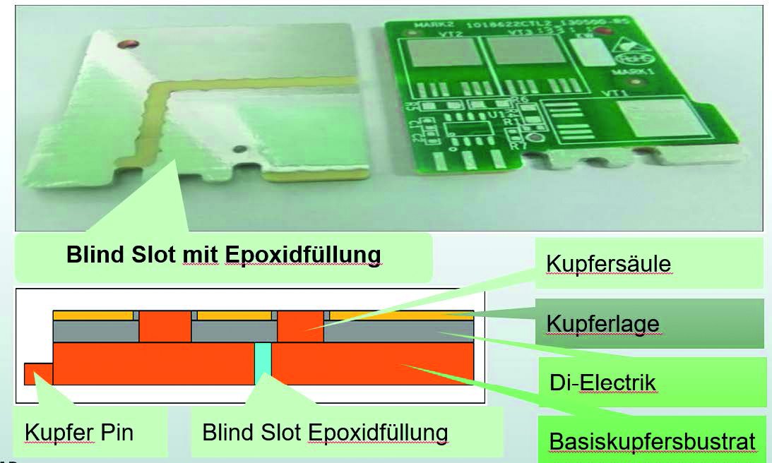 Fig. 8: Copper column technology
Copper coin technology
Copper-coin PCBs contain a solid copper piece that is inserted onto or into the PCB during production. They are typically positioned so that they lie under the components that need to be cooled after assembly.
Copper coins can provide about twice as much heat dissipation compared to a via farm (many vias arranged in blocks to dissipate heat). The copper piece can provide a direct thermal connection between the heat-generating component and the heat sink. This means that no other heat-conducting material is required.
Copper-coin technology is best suited when the components with the greatest heat generation are specifically concentrated there on a PCB. This solution offers local heat transfer, regardless of the number of layers or the PCB material.
During production, a copper coin piece is fitted into a prefabricated cut-out. It can be incorporated in various shapes and configurations. The designer chooses a good balance between cable routing, requirements of different power levels and cooling/heat dissipation requirements for each configuration. Figures 9 and 10 show a fixed copper path from layer 1 to layer 4, which acts as a mounting pad and provides the optimum heat dissipation channel for a heat source.
In cases where the pad size is too small and additional traces need to be routed under the hot pad, a copper coin can also be routed only up to a specific layer instead of continuously through the entire PCB. Figures 11 and 12 show the implementation of a copper coin that is placed between layer 4 and layer 2, but has no contact with layer 1.
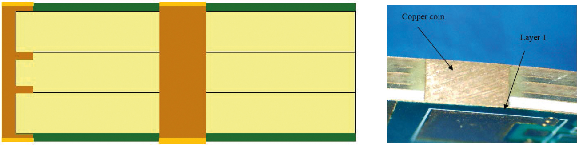 Fig. 9 + 10: Copper coin circuit board
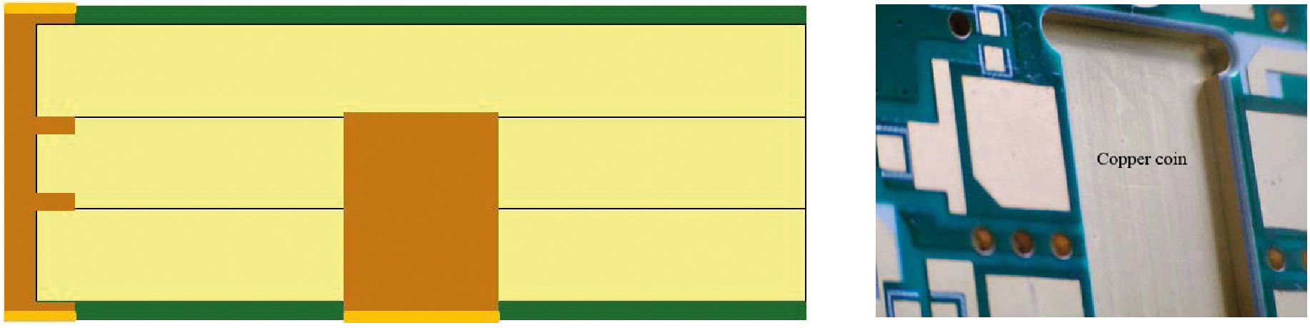 Fig. 11 + 12: Copper coin PCB
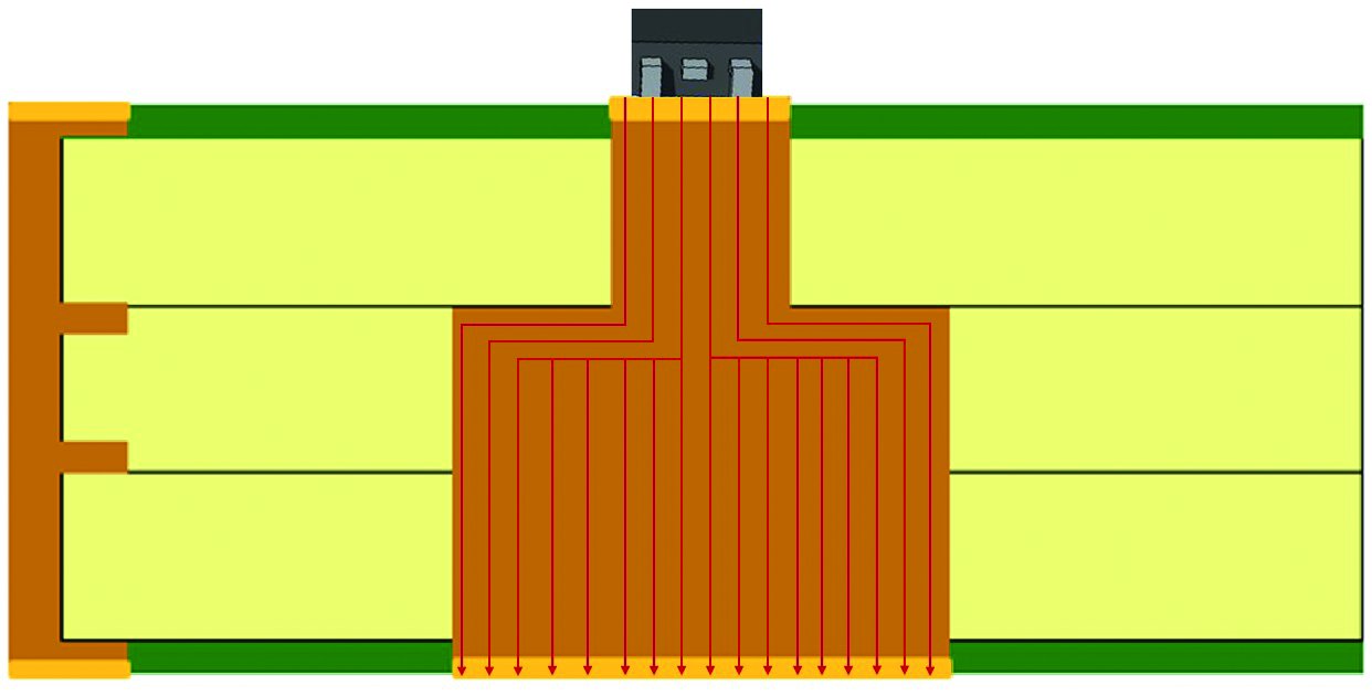 Fig. 13: Printed circuit board with copper coin in T-shape
Figure 13 shows an example of a T-shaped copper coin. The T-shape is an example of the design options available with copper coin technology. It is used when the size and shape of the heat-generating surface differs from the size and shape of the heat-dissipating surface - for example with a small hotspot and the use of a large heat sink. Copper coins therefore offer many possibilities for good compromises in terms of heat dissipation and the installation space required for this.
NCAB offers the necessary support for customer projects with regional and local teams when selecting the appropriate approach for thermal management.
