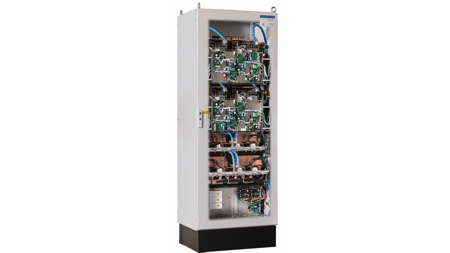
plating electronic GmbH from Sexau in the Black Forest designs direct and pulsed current sources for surface and electroplating technology, among others. With the new AFE rectifier technology, which was presented last year at the ZVO Surface Technology Days, mains current and mains voltage in electroplating plants can be optimized and harmonics prevented.
Harmonics in production plants
 Arbeitspunkt: 20 V / 2500 A (50 kW) DC") Fig. 1 a-d: Graphic representation of sinusoidal current draw: a) Operating point: 20 V / 2500 A (50 kW) DCTheissue of harmonics in electrical power supply networks is becoming increasingly important. In industrial networks in particular, voltage harmonics can lead to the failure of electrical consumers and thus to an impairment of the production process. In many industrial grids, harmonics are constantly present but are not recognized as critical. A frequent cause of harmonics is the use of non-linear loads in production processes. These include, for example
Fig. 1 a-d: Graphic representation of sinusoidal current draw: a) Operating point: 20 V / 2500 A (50 kW) DCTheissue of harmonics in electrical power supply networks is becoming increasingly important. In industrial networks in particular, voltage harmonics can lead to the failure of electrical consumers and thus to an impairment of the production process. In many industrial grids, harmonics are constantly present but are not recognized as critical. A frequent cause of harmonics is the use of non-linear loads in production processes. These include, for example
- Frequency converters for electrical drives
- Switch-mode power supplies for lighting (LED/energy-saving lamps)
- Battery charging systems
- IT systems etc.
These non-linear loads lead to a distortion of the mains voltage and current, which should ideally be sinusoidal. Particular attention must be paid here to the characteristic grid impedance (= alternating current resistance / complex internal resistance) of the electrical power supply network in the respective production plant. In practice, the terms "hard" or "soft" grid are often used for characterization. In a hard power supply grid (low grid impedance), a high harmonic content has less of an effect on the connected electrical loads than in a soft grid (high grid impedance).
If a certain grid or transformer-dependent limit value is exceeded, this can lead to problems in the power supply to electrical consumers and thus to their failure. An important parameter in this context is, for example, the short-circuit impedanceof the supply transformer for supplying the rectifier.
Parameters for assessing the power quality
 Arbeitspunkt: 29 V / 3450 A (100 kW) DC") b) Operating point: 29 V / 3450 A (100 kW) DCSomeparameters for assessing and evaluating the power quality are briefly explainedbelow. These parameters should always be taken into account when installing rectifiers (> 100 kW) and clarified with the project partners.
b) Operating point: 29 V / 3450 A (100 kW) DCSomeparameters for assessing and evaluating the power quality are briefly explainedbelow. These parameters should always be taken into account when installing rectifiers (> 100 kW) and clarified with the project partners.
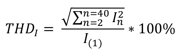
In practice, the total harmonic distortion of the current (THDI) and the voltage (THDU) are used to assess the quality of a supply network. These values are defined as follows:
Total Harmonic Distortion of Voltage (THDU) indicates the total harmonic distortion of the supply voltage. This value is defined as the quotient of the effective value of the harmonic voltages in relation to the effective value of the fundamental oscillation of the supply voltage. This value is often calculated as the geometric sum of all voltage/harmonic components in relation to the RMS value of the fundamental up to and including the 40th harmonic.
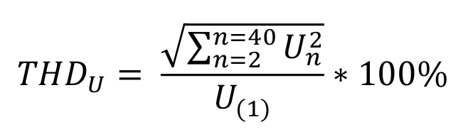
A low THDU value is generally considered to be synonymous with good voltage quality.
Total Harmonic Distortion of Current (THDI) indicates the total harmonic distortion of the current. This value is defined as the quotient of the effective value of the harmonic currents in relation to the fundamental oscillation of the current. This value is determined by measurement at a specific load point at a precise point in time. This value is often calculated as the geometric sum of all harmonic current components in relation to the fundamental current up to and including the 40th harmonic.
 Arbeitspunkt: 35 V / 4275 A (150 kW) DC") c) Operating point: 35 V / 4275 A (150 kW) DCAllgenerated harmonic currents in a network must flow through the existing impedances and all other parallel branches, which leads to non-linear voltage drops at the impedances. The resulting harmonic voltages spread across the entire network and cause distortion of the supply voltages on other devices. As a result, the harmonic distortion of the current is a cause of the voltage distortion.
c) Operating point: 35 V / 4275 A (150 kW) DCAllgenerated harmonic currents in a network must flow through the existing impedances and all other parallel branches, which leads to non-linear voltage drops at the impedances. The resulting harmonic voltages spread across the entire network and cause distortion of the supply voltages on other devices. As a result, the harmonic distortion of the current is a cause of the voltage distortion.
Existing supply transformer:
- Short-circuit impedance of the feed transformer -UK value: this information is used to assess whether the existing energy network is a "soft" or "hard" network. The short-circuit impedance can be used to derive an impedance value for the energy supply network.
- Utilization of the feed-in transformer: for existing systems, the utilization of the existing supply transformer for the rectifiers should be checked. Particular attention should be paid to the available reserves in order to operate the rectifiers in accordance with the specifications.
The points mentioned above are only intended for a rough assessment of an existing grid. A meaningful analysis of the customer network can only be carried out by a specialist company. This analysis takes into account the interaction between the existing generation and consumption systems at typical operating points. A network simulation is often carried out in order to identify weak points and take suitable countermeasures.
Harmonics in connection with (galvanic) rectifiers
In principle, switched-mode power supply (SMPS) or thyristor-based rectifiers with passive rectification generate harmonic currents/network perturbations. These lead to a non-sinusoidal current draw (distortion) which can be measured as current harmonics/grid perturbations.
Technical measures to compensate for harmonics
 Arbeitspunkt: 40 V / 5000 A (200 kW) DC") d) Operating point: 40 V / 5000 A (200 kW) DCPracticablesolutions for compensating harmonics are
d) Operating point: 40 V / 5000 A (200 kW) DCPracticablesolutions for compensating harmonics are
- Passive harmonic filters: these filters can be used to achieve a significant reduction in the harmonic content and an increase in the power factor. However, these filter systems only work effectively at nominal load power, as the electronic components are designed for the nominal operating point. In partial load operation, the harmonic component increases and the power factor is reduced. The resulting voltage drop across the filter must be taken into account.
- Active harmonic filters: The disadvantages of passive harmonic filters mentioned above can be compensated for by an active filter solution. In principle, active harmonic filters can be described as a dynamic current source. These filters are installed in parallel with the load and analyze the resulting current harmonics. Based on the analysis, a corresponding, opposite current can be fed in. This leads to a significant reduction in harmonics. As the filter is installed in parallel with the load, it is not necessary to generate the entire load current, only the required compensation current.
- Active rectification - Active Front End (AFE) technology: loads with Active Front End technology have active rectification of the alternating current, resulting in a current draw with an almost perfect sine wave shape. This leads to a significant reduction in harmonics and an increase in the power factor to almost 1.00. This is accompanied by a reduction in the phase current, which means that the power supply to the loads can be designed for almost nominal active power. From a technical point of view, Active Front End technology is the best way to directly reduce harmonics. This technology has already been established and proven in industrial practice for several years, e.g. for the operation of:
- Frequency-controlled drives
- Inverters for handling and processing machines
- Robots and handling devices
Compared to consumers with active or passive mains filters, devices with AFE technology can have a higher electrical efficiency. This is because no additional components are installed that reduce the system efficiency.
Advantages of AFE technology
Rectifiers with AFE technology behave like a resistive load in the electrical consumer system. This behavior is made possible by the PWM control of the rectifier, which leads to a significant reduction in the peaks of current harmonics.
The sinusoidal current draw prevents voltage distortions, so harmonic compensation for the rectifier is not necessary. This is associated with an increase in the power factor from the standard 0.95 to 1.00. Harmonic oscillations (THDI) are thus reduced to less than 3 %. The in-phase current draw leads to a reduction in the phase current and therefore to a lower load on the supply transformer. Also worth mentioning are
- no commutation dips, i.e. no impairment of other electrical consumers
- very low reactive power due to ohmic behavior of current and voltage
- sinusoidal current draw leads to lower mains load
- No voltage distortion and therefore no need to oversize the supply transformer
- Excitation to mains oscillation is prevented
Figures 1a-d illustrate the sinusoidal current draw from the supply grid. The reference rectifier in this case is a pe5910 Power Station with AFE technology - 40V/5000A DC or 200 kW DC.
