
The model presented can be used to calculate rinsing cascades, whereby immersion and spray rinsing can also be represented for non-ideal rinsing. The flexible model can also be used to calculate circuit rinsing, recirculation rinsing and spray chamber rinsing.
6 Examples
6.1 Spray rinsing with fresh water or with follow-on water
A 3-stage rinsing cascade is to be equipped with spray nozzles on all three stages. The spray nozzles are used for additional spraying of the goods as they are lifted out of the respective immersion rinse. From the coating process, 1.1 liters with a concentration of 50 gl-1 is carried away per product carrier. As the viscosity of the rinsing water is significantly lower than that of the process solution, the carryover from the rinsing stages is slightly lower at 1.0 liter. 10 product carriers are rinsed per hour.
Non-ideal rinsing must be assumed for exchange rinsing. The effect is particularly pronounced at low concentrations, i.e. in the rear sinks. Based on [14], the factors of incomplete mixing for the three sinks are assumed to be
<50>
Spray rinsing with fresh water
First, the rinsing result should be considered when spray rinsing is carried out with fresh water over all three stages. The corresponding 3-stage rinsing cascade with externally fed spray nozzles is shown in Figure 12 . The rinsing cascade is fed by spraying 10 liters per product carrier above the third sink. A minimum spray volume of 5 liters is sprayed over each of the first two sinks. The spray rinsing volume flows result from a throughput of 10 WT/h:
<51>
 Fig. 12: 3-stage spray rinse cascade - spraying with fresh water
With the different spray volumes, a slightly different effect of the spray rinsing is expected. Based on the values determined experimentally in [15], the spray rinsing factors should be cautiously assumed with the following values:
<52>
i.e. due to the lower spray volume, a slightly lower effect of spraying is assumed in the first two stages compared to the third stage.
This defines the parameters for setting up and solving the model shown in section 3.
In the first step, equations <26> are used to calculate the overflow volume flows of the flushing stages:
<53>

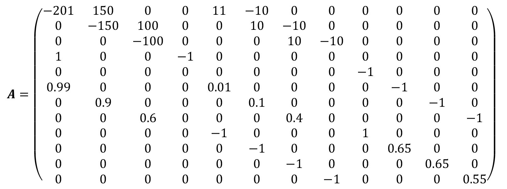
To set up the volume flow and coefficient matrix A, these volume flows as well as the factors for incomplete mixing and the spray flushing factors are required. Structural parameters must also be specified. For example, the factors according to equation <25> are δ1 = δ2 = 0, as fresh water is used for spraying above stages 1 and 2 instead of water from the next stage. Furthermore, the factor according to equation <16> is ε = 0, as there is no pre-dipping step here. The matrix A can therefore be set up according to equation <29
<54>
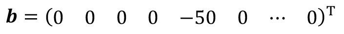
The input vector b according to equation <31> is considerably simplified, as the externally supplied water has a concentration of zero. Only the fifth vector element is occupied:
<55>
To solve the linear system of equations, the inverse of the volume flow and coefficient matrix (54) is calculated:
<56>
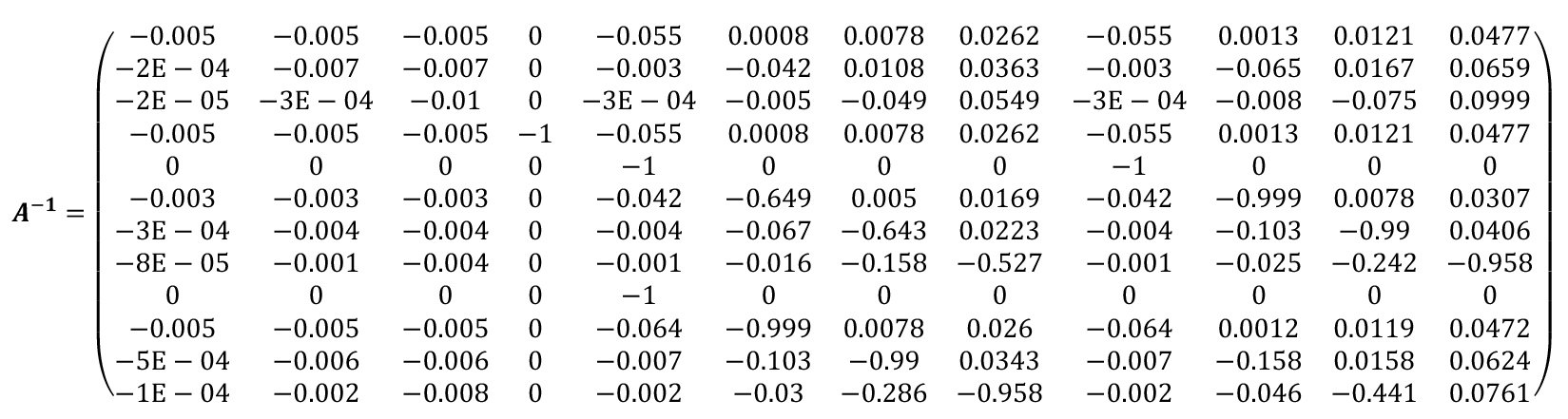
The required concentration vector can now be calculated by multiplying the inverted matrix A-1 by the input vector b(equation <33>). The result is
<57>
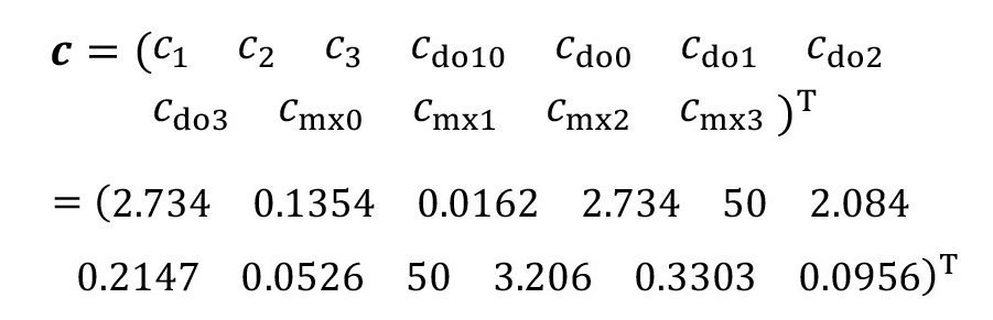
The first three values indicate the concentrations in the flushing stages. The fourth value (carryover after pre-dipping) is not relevant here, as no pre-dipping takes place. This is followed by the carryover concentrations from the treatment process and from the three rinsing stages. The last four values represent the concentrations after immersion rinsing and before spraying. These are internal calculation variables of the model and have an informative character in the result vector.
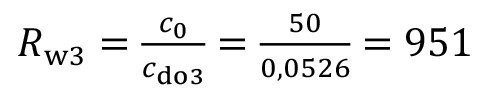
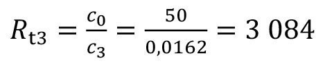
The most important result is the carryover concentration after the last rinse cdo3. This is set in relation to the concentration of the treatment process in order to be able to make a statement about the rinsing quality achieved. Equation <34> is used to calculate the corresponding rinsing criterion:
<58>
The concentration of liquid residue on the fabric after the rinsing process has been completed is considered here. However, a distinction must be made between the concentrations:
- A stationary 16.2 mg/L is present in rinsing stage 3.
- Due to non-perfect rinsing (factor of incomplete mixing 40 %), the carryover during removal is 95.6 mg/L.
- Spray rinsing (effectiveness 45 %) again reduces the concentration of the final carryover to 52.6 mg/L.
When comparing the rinsing criterion with data from the specialist literature, it must be noted that the term "rinsing criterion" usually refers to the concentration in the sink and therefore applies in general terms:
<59>
and here specifically:
<60>
Strictly speaking, this value expresses the dilution in the sink rather than the final rinse quality. Accordingly, the term "degree of dilution" will be used below for this rinse water-related rinsing criterion. In contrast, the value Rw related to the product(eq. <34>) is referred to as the rinsing criterion. The example illustrates that a corresponding differentiation is necessary for non-ideal rinsing.
Spray rinsing with follow-on water
In the first two rinses, spray rinsing can also be carried out with rinse water from the following rinse stage instead of fresh water, see Figure 13. To calculate the steady-state concentrations, only a few parameters of the model need to be changed:
- Type of spray rinsing: δ1 = δ2 = 1.
- The external feed flows V.sr1 and V.sr2 are omitted, i.e. they are set to zero.
- Spray rinsing over the first two rinsing stages can now be carried out without using more water than in the last rinsing stage with 10 l/WT. Accordingly, a spray rinsing effect is assumed as above the 3rd stage:
<61>
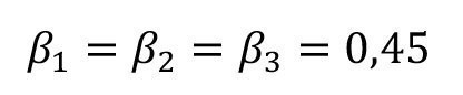
 Fig. 13: 3-stage spray rinsing cascade - spraying with follow-up water
The overflow volume flows according to equations <26> are then
<62>

The modified volume flow rate and coefficient matrix A is therefore according to equation <29>:
<63>
The entry vector b remains unchanged, see equation <55>. The required concentration vector can again be calculated according to equation <33>. This results in c3 = 27.3 mgl-1 for the concentration in sink 3 and cdo3 = 88.5 mgl-1 for the final carryover concentration. Accordingly, the flushing criterion Rw3 = 565 and the dilution factor Rt3 = 1832. The flushing criterion is therefore lower than in the case described above. However, the consumption of fresh water is significantly lower here (100 lh-1 instead of 200 lh-1), as there is no spraying with fresh water via stages 1 and 2.
If the same amount of fresh water is fed completely into the third stage V.sr3 = 200 lh-1, the result is a rinsing criterion of Rw3 = 1477 with the same assumed spray rinsing parameters. In order to achieve the same rinsing criterion as for spraying with fresh water Rw3 = 951 (see above), the water feed into rinse 3 can be reduced to V.sr3 = 143 lh-1.
As the calculations show, spraying with water from the next stage reduces the amount of water. However, this technique can be problematic, as the rinse water sprayed from the downstream stages contains the substances from the treatment process in low concentrations. It must be checked on a case-by-case basis whether this could pose a health risk to employees. This may be a reason to spray with fresh water throughout despite the higher water requirement.
6.2 Example: Recirculating sink
A 3-stage rinsing cascade with a final ion exchange recirculating rinse is considered. From the treatment process, 1.1 liters of a process solution with a concentration of 100 g/L is carried over per product carrier. The carryover from the rinsing stages is slightly lower at 1.0 liter per product carrier. 10 product carriers are rinsed per hour. Non-ideal rinsing must be assumed for immersion rinsing. Based on [14], the factors for incomplete mixing for the three rinses and the final recirculation rinse should be assumed to be
<64>

The cascade rinse is fed by spray rinsing with fresh water above the third rinse stage. 10 liters are sprayed per product carrier. A value of 0.5 is assumed as the spray rinse factor. The circulation volume flow is 300 liters per hour. The aim is to achieve a rinsing criterion of 2,000. The flushing system is shown in Figure 14.
 Fig. 14: Flushing cascade with final recirculation flush
When setting up the model, the recirculation rinse is described as in section 5.1 by an equal inflow and outflow volume flow, whereby the water flowing back from the ion exchanger has a concentration of zero. Equations <39> to <41> therefore apply:
<65>
The model is also assigned the following parameters:
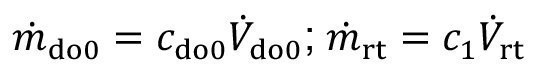
- Carryover volume flows
<66>

- Carryover concentration from the treatment process
<67>
- Spray rinsing volume flow
<68>
- Spray rinsing factor
<69>
All other model parameters are assigned the value zero.
The solution of the model equations is used to check whether the desired total flushing criterion of Rw,set = 2000 is achieved. As described in section 4.1, the overflow volume flows are calculated after the compilation of all model parameters. According to the equations <26>:
<70>

With these overflow volume flows and the parameters listed above, the volume flow and coefficient matrix A can be set up according toequation <29>. In addition, the entry vector b is formed(equation <30>), which, as in the previous example, is only occupied in one element. After inverting the matrix A and matrix multiplication with the vector b, the concentration vector c of the flushing system is obtained according to equation <33>.
The carryover concentration from the recirculation rinse contained in the vector is cdo4 = 0.248 gl-1. This means that the achieved rinsing criterion of Rw = 403 is far too low, corresponding to the required value of 2000. A first idea to solve this problem could be to increase the circulation volume flow. However, some calculation tests with the model show that even with a significantly higher circulation volume flow, the flushing criterion reaches a maximum value of 410.
It is more effective to increase the cascade volume flow. This allows the required flushing criterion to be set. As described in section 4.2, determining the required feed volume flow corresponds to solving a one-dimensional optimization problem. This can be easily solved in Microsoft Excel, for example, using the target value search. Again with the circuit flow 300 lh-1, the result for the feed volume flow is V.if3 = 278 lh -1. Together with the spray rinsing, this means a fresh water requirement of 378 lh-1.
This raises the question as to why such a large amount of water is required to achieve the required rinsing criterion despite 4-stage rinsing including circulation rinsing. The problem becomes clear from the calculated concentration vector:
<71>
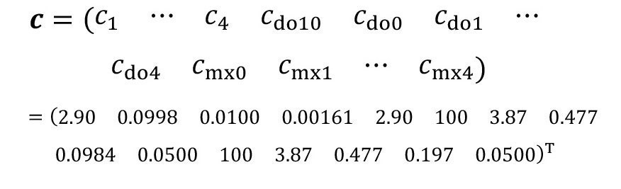
When comparing the rinse water concentrations ck with the carryover concentrations cdo,k, it can be seen that the carryover on the fabric is more concentrated than the corresponding water in the rinse tanks. This is particularly pronounced in the last two rinses. This is due to the pronounced effects of incomplete mixing, which are described by the factors of incomplete mixing according to equation <64>. Non-ideal rinsing effects generally occur when rinsing times are too short. The phenomenon is also pronounced at very low concentrations, i.e. in the backwash. The factors presented in [14] of 0.4 for the third and 0.5 for the fourth rinsing stage were determined experimentally at a rinsing time of 40 seconds.
In order to achieve the desired rinsing criterion without high water consumption in the example considered here, it is necessary to counteract the effects of incomplete mixing. In order to improve the mixing, the dwell time in the circulation rinse could be extended to cycle time, for example. With a rinse lasting several minutes, the rinsing effect could be improved to such an extent that the incomplete mixing factor is reduced to α4 = 0.05, for example.
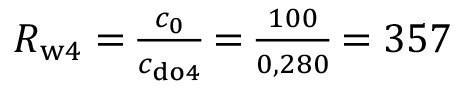
With this modified parameter, the concentration of the rinse water in the recirculation rinse is 0.0150 gl-1 (dilution factor Rt4 = 6,675) and the carryover from the recirculation rinse is 0.0386 gl-1 (rinsing criterion Rw4 = 2588) for a recirculation volume flow of 300 lh-1 and a cascade volume flow of 100 lh-1. This means that the achieved rinsing criterion is even higher than the required value. In order to set the specified value of 2000, the feed flow of the cascade can be reduced to 84 lh-1.
6.3 Example: Recirculation rinse
In a drum system, a sequence of four rinsing stages takes place after a metal separation process. The first stage is used as a recirculation rinse (so-called economy rinse). Coating takes place in several parallel positions. The resulting electrolyte surface and the increased temperature lead to an evaporation of 15 liters per hour. The corresponding volume deficit is compensated for by recirculation from the economy rinse. On average, 8 drums are put through every hour. 1.25 liters are carried over per drum, whereby the carryover from the process and from the rinsing stages is assumed to be the same. The concentration in the process is 100 gl-1. Rinsing in the drums is not ideal. In the final rinsing stage, this effect is counteracted by a longer rinsing time. Accordingly, the factors of incomplete mixing are assumed to be the same:
(72>

Rw4,set = 1000 is defined as the flushing criterion. The aim is to determine how the rinsing criterion and the degree of recirculation behave when the economy sink is filled either with fresh water or with rinsing water from the following rinsing stage.
Filling with fresh water
The case in which the volume deficit resulting from recirculation is filled with fresh water is considered. The corresponding structure is shown in Fig. 15. First, the steady-state conditions are calculated for the case where 100 lh-1 of rinse water is fed into the last cascade rinse every hour.
 Fig. 15: Recirculation sink with fresh water supply
As described in section 5.2, the discharge from the second sink is calculated in such a way that there is no overflow to the first stage. The greatly simplified equation <45> then reads:
<73>
Rinsing solution is taken from the first rinsing stage for recirculation and filled with fresh water:
<74>

According to the scenario described above, the following parameters are also used:
- Carryover
<75>

- Feeding of the cascade
<76>
All other model parameters are set to zero. The overflow volume flows then result according to equations <26>:
<77>

The volume flow and coefficient matrix A(equation <29>) and the input vector b(equation <30>) are formed using the overflow volume flows and the parameters listed above. The concentration vector c can then be calculated according to equation <33>.
The rinsing criterion is in turn calculated from the ratio of the concentrations in the process and in the carryover from the last rinse:
<78>
The associated degree of dilution of the last rinse is Rt4 = 544. The degree of recirculation indicates what proportion of the substances carried over from the treatment process can be recirculated:
<79>
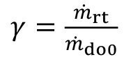
The two mass flows are calculated as follows:
<80>
The degree of recirculation therefore follows:
<81>
The degree of recirculation is quite good; after all, almost 60 % of the material losses are avoided.
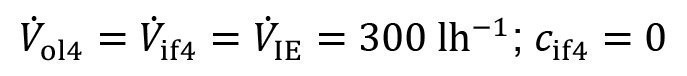
The flushing criterion, on the other hand, is not particularly high. If it is to be increased, the rinse water feed must be increased. A targeted search (math. optimization) shows that, for example, a rinsing criterion of Rw4 = 1000 is achieved with a water input of V.if4 = 275 lh-1. The degree of recirculation is not affected by this, as the recirculation flush is completely decoupled from the subsequent flushing cascade in this scenario.
Filling with rinse water from stage 2
The case in which the volume flow from the flow cascade into the recirculation sink corresponds exactly to the recirculation volume flow will be considered first. Fresh water is no longer fed into the recirculation sink(V.if1 = 0). Instead, the volume flow from the second to the first stage is set to be equal to the return flow, see Fig. 16.
 Fig. 16: Recirculation sink with supply from the next stage
<82>
In order to realize this volume flow, a correspondingly reduced discharge from the second stage takes place:
<83>
Again, the vector of stationary concentrations of the 4-stage flushing system can be calculated as described above. From this, equations <78> to <80> can be used to calculate the flushing criterion and the degree of recirculation:
<84>
The degree of recirculation can therefore be increased slightly (approx. 4 percentage points) by recirculating from the second to the first sink. However, the total flush criterion will be slightly lower.
Setting the flush criterion and recirculation rate
To increase the flush criterion, the feed flow into the last sink can be increased. Alternatively, it is possible to increase the flow rate from level 2 into the return sink. To do this, reduce the discard volume flow V.o12. The surplus produced in stage 1 is not recirculated but discarded. Figure 17 shows this structure schematically.
 Fig. 17: Partially cascaded recirculation sink
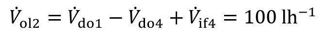
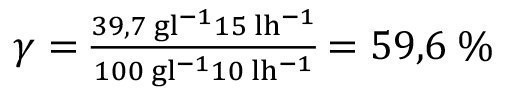
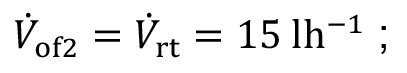
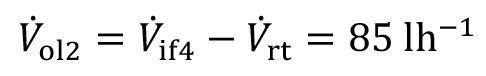
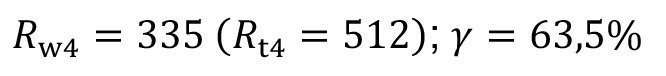
An optimization calculation shows, for example, that the flushing criterion Rw4 = 1000 is achieved with a discard of V.ol2 = 29.3 lh-1. There is a throttled flow into the recirculation sink of V.of2 = 70.7 lh-1. Of this, V.ol1 = 15 lh-1 is recirculated and V.of1 = 55.7 lh-1 is discarded. However, at the concentration of c1 = 13.5 gl-1 in the recirculation sink, the degree of recirculation is only y = 20.3 %.
Now the desire could arise to realize both a specified rinsing criterion and a specific degree of recirculation at the same time. This is possible with the flushing cascade with a throttled recirculation flush, as there are two degrees of freedom to influence the two target variables with the feed volume flow in stage 4 and the reject volume flow from stage 2.
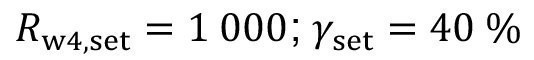
As an example, the two target variables in the described flushing system are specified with
<85>
These target values are to be set by changing the inflow into the cascade V.if4 and the discharge from sink 2 V.ol2. Finding the necessary volume flows corresponds to solving a two-dimensional optimization problem. In Matlab, routines are available for this in the Optimization Toolbox. The Solver Add-in can be used in Microsoft Excel .
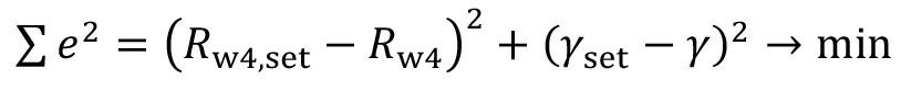
In general, multidimensional optimization requires an objective function that specifies a scalar objective criterion. It is usual to formulate a sum function of the quadratic deviations. The optimization algorithms then attempt to minimize the error sum of squares by varying the two variables sought. In this example, the corresponding target function is
<86>
The flushing criterion and feedback rate are calculated in each optimization step using the stationary flushing model presented. If the corresponding mathematical optimization is carried out with technically sensible starting values, the result is found without any problems:
<87>
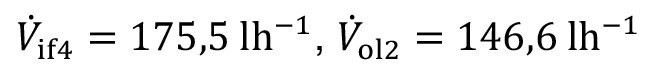
With these volume flows, the flushing criterion Rw4 = 1000(Rt4 = 1924) and the degree of recirculation y = 40 % are set.
To be continued ...
Literature
[14]Buczko, Z.: Multistage Rinsing Systems in Electroplating Lines - New Method of Calculating Based on Imperfect Mixing Model, Transactions of the Institute of Metal Finishing 71(1993)1, 26-29
[15]Giebler, E.; Hauser, S.; Neumann, K.-H.; Reich, A.: Effective Method for the Investigation of Spray Rinsing Processes, Galvanotechnik 95(2004)1, 214-221
