The trend towards lightweight construction in conjunction with the high safety standards in automotive engineering has led to a mixed construction of different metallic materials, which are combined with different joining processes. This has also increased the demands on surface technology.
Mixed construction in automotive engineering as a challenge for surface technology
The trend towards lightweight construction in conjunction with the high safety standards in automotive engineering has led to a mixed construction of different metallic materials, which are combined with different joining processes. This has also increased the demands on surface technology.
In automotive body construction, the mixed construction method with a material mix of conventional and high-strength steels, aluminum alloys and, if necessary, with the aid of CFRP structures has prevailed for around two decades. This principle of combining different materials in one construction, depending on the function and installation position, has led to increased safety reserves in crash-relevant installation positions on the one hand and to a reduction in the weight of the bodyshell on the other.
However, the material mix of steel and aluminum also shows that there is still a fundamental need for action in science and technology, as thermal joining processes are not available ready for series production and consequently a great deal of effort has to be made with well-known mechanical joining technology. However, this shortcoming has also led to the development of newer mechanical joining processes such as semi-tubular punch riveting or friction element welding. At the same time, surface technology for coating high-strength fasteners is in greater demand than ever before. The electrochemical compatibility of different material pairings remains a major challenge.
Use of materials in mixed construction
The dominant materials in automotive mixed construction are aluminum sheets and extruded alloys of the AlMgSi alloy system as well as the higher-strength micro-alloyed steels and - for around two decades - the ultra-high-strength shape-hardened steels.
The ultra-high-strength steels allow a certain weight reduction, but very thin-walled sheets cannot be used because the product of modulus of elasticity and moment of inertia, the bending stiffness, would then be reduced too much.
|
Cast aluminum alloys |
|||
|
Alloys |
Casting process |
Heat treatment |
Example |
|
AlSi10MgMn |
Vacural die casting |
T6 or T7 |
Casting nodes |
|
AlSi7Mg |
Permanent mold casting |
T6 or T7 |
Structural parts |
|
Magnesium casting alloys |
|||
|
AM50 / AM60 / AZ 91 |
Die casting alloys, thin-walled |
Long-term thermal stability is sometimes required |
Only as an assembly part, e.g. strut brace |
|
Extruded profiles / forged parts |
|||
|
Alloys |
Casting process |
Heat treatment |
Example |
|
EN-AW 6082 [AlMgSi 1] |
Drop forging for structural components or continuous casting / extrusion / T6-WB |
T6 or T7 |
Suspension strut mount, body structure |
|
Sheet metal alloys |
|||
|
Alloys |
Casting process |
Heat treatment |
Example: EN-AW |
|
EN-AW 6016 [AlMg0.4Si1.2] |
Aluminum coil passivated with Cu < 0.1 wt.% |
T4 and partial curing with CDC process 20 min/185 °C (T64) |
Outer skin parts |
|
EN-AW 6009 [AlMg0.6Si0.8] |
Aluminum coil passivated with Cu < 0.1 wt.% |
T4 and partial curing with KTL process 20 min./185 °C (T64) |
Inner parts |
|
AS 250 [EN-AW 6111 and EN-AW 6016] |
Continuous casting and rolling of monolithic ingots down to the sheet thickness; outside EN-AW 6016, inside EN-AW 6111 |
T4 and partial curing with KTL process 20 min/185 °C (T64) |
Side panel frame, inner door section |
Due to the low elongation at break of the ultra-high-strength steels (Rm > 1200 MPa, A80 < 5 %), these must be bonded to soft body structures so that, in the event of a load, the impact energy is partly transformed into elastic distortion energy (martensite lattice) and partly into plastic deformation energy of the bonded structures. Otherwise, the high-strength steels would break in the event of a crash.
Joining steel and aluminum is difficult and costly, as thermal joining of aluminum and steel is not possible due to very unfavorable effects in terms of cracking and brittleness. As a rule, intermetallic phases of the form FexAly (often Fe2Al5) are always formed, which lead to a severe loss of strength of the weld group. Even processes with low heat input ("cold metal transfer") have so far failed to achieve a breakthrough. This leaves only the mechanical joining technique using screws or rivets with appropriate sealing measures to prevent contact corrosion.
Tables 1 and 2 provide an overview of the materials commonly used in mixed construction in automotive body construction.
|
Higher-strength and high-strength steels |
|||
|
Steel type |
Forming / heat treatment |
Microstructure / surface |
Example |
|
High-strength IF steels and micro-alloyed steels according to DIN EN 10346 |
Cold or hot rolled soft strip; baking of the coating (170 °C / 20 min.) leads to C and N diffusion and dislocation inhibition in microalloying, increase in yield strength |
Soft ferritic matrix, micro-alloying using Ti, Nb, V. Higher-strength IF steels alloyed with P, Si, Mn. As a rule, galvanized strip is used on both sides |
Roof, side wall frame inner sheet |
|
Dual-phase steels according to DIN EN 10346 |
Cold-formed strip; HTMB (deformation in the austenite area) with quenching from the austenite area to achieve martensite |
Ferritic-martensitic matrix, defined alloy of manganese, chromium and silicon. As a rule, galvanized strip is used on both sides |
Body structure components such as side members, inner sill panels |
|
Complex-phase steels according to DIN EN 10346 |
Hot or cold rolled strip, but mostly hot rolled. Heat-treated using HTMB. Partly stress-relieved annealed |
Ferritic-bainitic-martensitic matrix, very fine-grained microstructure due to delayed recrystallization and precipitation of microalloying elements. Usually electrolytically galvanized on both sides |
B-pillar reinforcement or side impact beams |
|
Martensitic steels according to DIN EN 10083 |
Hot-rolled strip with AlSi7.5 coil coating or with zinc coating. Initial condition ferritic-pearlitic. Produced by press hardening with quenching from the austenite region |
Martensitic matrix. No hot-dip or electrolytic galvanizing possible. Formation of a diffusion layer AlxFey or FexZny. However, zinc phosphating is still possible |
A and B mullions, interior and exterior sills |
In addition to the materials listed in the tables, there are also plastic applications. These include fiber-reinforced structures (CFRP, SMC) and mixed polymers (e.g. PP-EPDM for mudguards).
In the case of CFRP structural components, considerable expenditure is also required for mechanical joining and corrosion protection measures, as the C-long fibers are always exposed when fasteners are used and critical local elements can arise as a result. In most cases, however, CFRP structural components are (re)used in the non-corrosive interior.
The introductory illustration of the article shows the wide range of materials used in the Audi Q5 Etron, and typical applications for martensitic steels are also shown.
Joining technology
Steel sheets are joined together by resistance spot welding, laser welding or laser soldering (e.g. side panel frame to roof), while MIG welding, laser welding and increasingly also spot welding are established processes for aluminum-aluminum joints, depending on the component thickness. This thermal joining technology can only be used in part for mixed construction joints. Higher-strength IF steels and micro-alloyed steels can be joined to form-hardened steels using spot-weld bonding. With the use of aluminum in car body construction, there are limits to thermal joining technology, as only aluminum structural components can be thermally joined together. In this respect, mechanical joining processes had to be developed for mixed construction. In particular, the further developed semi-tubular punch riveting and friction element welding should be mentioned here(see Fig. 1).
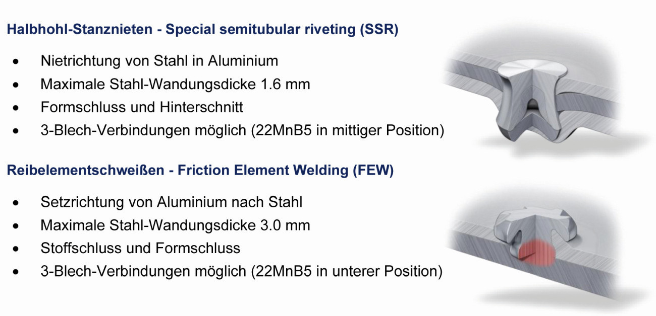 Fig. 1: Newly developed joining technologies for mixed construction
Hardened and tempered steel fasteners are used for both joining processes. The friction elements are tempered to a tensile strength of around 800 ... 1000 N/mm2 depending on the steel quality, while the self-pierce rivets have a very high tensile strength of up to 1800 N/mm2.
The semi-tubular self-pierce rivets are electroplated with zinc-nickel and then passivated. Additional measures are therefore required for the self-pierce rivets by means of longer heat treatment (8 h / 210 °C) as well as proof of a very low limit value in the total hydrogen content (in accordance with ASTM E 1447).
For the high-strength self-pierce rivets, several optimization stages were carried out with regard to the geometric design for 2-sheet and 3-sheet joints in order to ensure residual compressive stresses in the joined state(see Fig. 2).
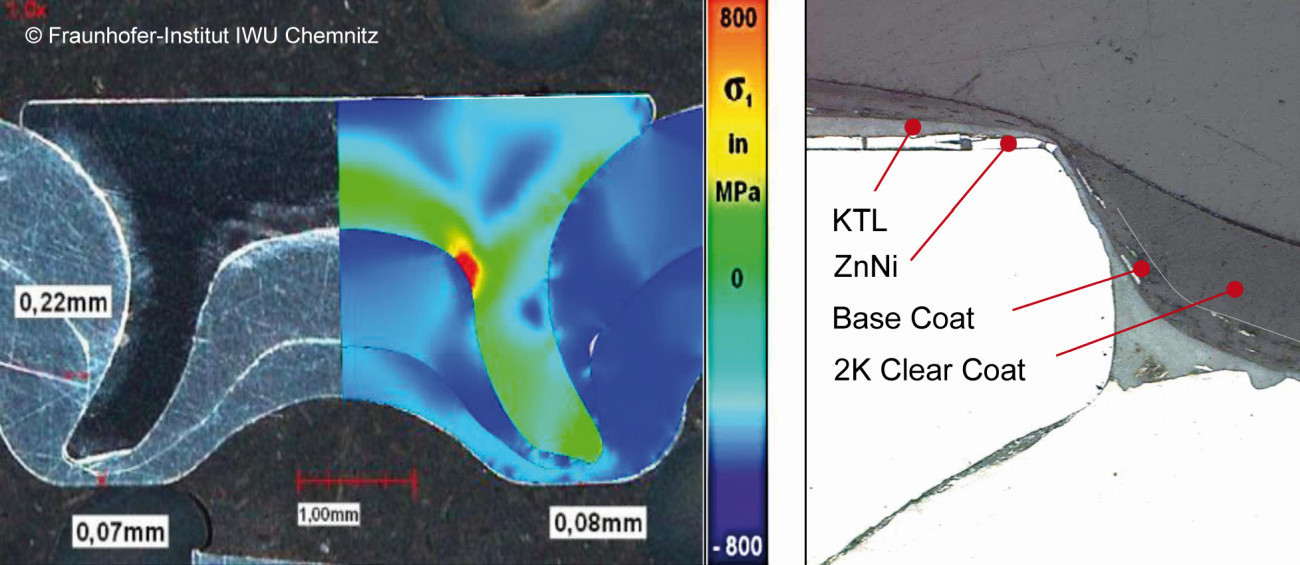 Fig. 2: Stress distribution in the joined state and coating system
 Fig. 3: Friction element welding with high-strength steel and joining with aluminiumTheroot radius in particular was optimizedforthe predominant compressive stress state. The small tensile stress amplitude is usually unavoidable due to the expansion of the rivet feet, but is not critical to this extent. Figure 2 shows that in the event of damage to the ZnNi layer at the edge, the paint system takes over the protective effect. As a rule, there are additional seals over the rivet points. The connecting elements for friction element welding not only implement a mechanical clamping technique like self-pierce rivets, but also thermal joining (see Fig. 3).
After clamping the aluminium and steel sheets, the friction element is applied and penetrates the aluminum cover sheet under rotation and pressure (heating and plasticizing the material, but without melting it). In the subsequent process step, the steel base plate is heated by the rotating friction element under axial force. At the end of the friction process, the rotation is slowed down. The upsetting pressure remains. The heat generated welds the friction element to the base plate. There is a force and form fit between the aluminum and steel.
The friction elements are also ZnNi-coated and withstand the high loads during joining very well, as illustrated in Figure 4.
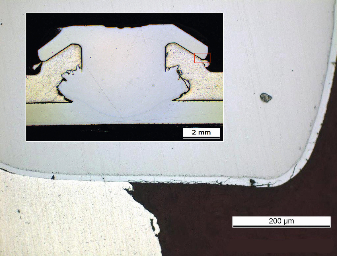 Fig. 4: Friction element with galvanic zinc-nickel coating on the upsetting edge in contact with aluminum
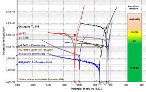 Fig. 5: Table showing the exchange current density at the free corrosion potential for selected coatings in reference to aluminum and gray cast ironInaddition to the usual corrosion tests in the Group P1210 test and the salt spray test, electrochemical tests were also carried out on the coating of the self-pierce rivets. Figure 5 shows the corrosion current densities of selected coatings at the free corrosion potential, whereby the measurement was also carried out on the respective coated rivet. The very good behavior of the zinc flake and zinc-nickel systems became clear. ZnNi-coated self-pierce rivets are widely used in the VW Group due to the improved adhesion and cohesion of electroplated coatings compared to stoving systems. In addition, the free corrosion potential of zinc-nickel is also close to that of aluminum, so that contact corrosion can be largely ruled out.
A major difficulty is the perfect coating of the small self-pierce rivets in the barrel process, which requires a specially adapted rotation and tilting technique.
Mixed construction and electrochemical compatibilities
The material mix on the body shell always requires that suitable water drainage is provided at the material contact points, that the flanges are sealed and, if necessary, additionally bonded and that the correct material or the adapted coating is used. Figure 6 shows the flanging of the aluminum side wall frame around the edge of hot-formed steel (Usibor). Such flanging areas between aluminum and steel must always be bonded (so-called 130 % bonding) and additionally sealed. The martensitic steels that have an AlSi coil coating before press hardening form an AlxFey diffusion coating, at least after austenitizing and cooling, which has a certain compatibility with aluminium (see Fig. 7).
This diffusion coating, which predominantly contains aluminum in a brittle intermetallic phase, causes only minor contact corrosion on the aluminum, but has a tendency to a certain brittleness, is more difficult to passivate and clearly shows where the problems lie in the thermal joining of aluminum and steel (see Fig. 8).
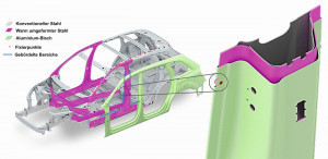 Fig. 6: Material mix on the bodyshell of the Q7 with flanging seam technology on the side wall frame to the B-pillar (see detailed illustration)
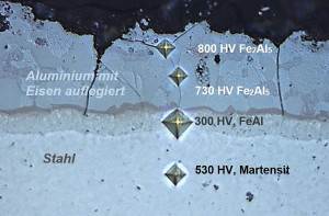 Fig. 7: Current density potential curves of selected steels with and without additional galvanizing in reference to Usibor and the aluminium alloy AA 6016
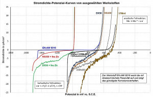 Fig. 8: Formation of an iron-aluminum diffusion layer after press hardening of AlSi7.5-coated high-strength steel. The high hardness of the diffusion layer always causes a certain tendency to crack.
Electrolyte: 1 M aqueous NaCl solution
Temperature: 20 °C
pH value: 7.0
Agitation: 400 rpm
Potential feed: 1 mV/s
Sample conditioning in the electrolyte
60 min. before measurement
Alternatively, some OEMs use a galvanized layer as coil cladding for high-strength steels, which is converted into different zinc-iron phases during austenitization due to iron diffusion and therefore does not sublimate. This concept is used by the BMW Group, among others, and requires very precise temperature and time control. The concept is now also used by VW and Porsche for various models. The ZnFe system has minor advantages in terms of pre-treatment and paint adhesion, whereas the FeAl(Si) system has advantages in terms of stone chip resistance.
Figure 7 illustrates that non-galvanized deep-drawing and heat-treated steels cannot be used under any circumstances, as otherwise there is a permanent risk of contact corrosion, even if the steels have a KTL coating. In areas of permanent moisture, KTL coatings are soaked through to the substrate surface, resulting in delamination due to iron oxidation. In contrast, the free corrosion potential of hot-dip galvanized applications is in the passivity range of conventional aluminium alloys and is largely compatible with aluminium alloys.
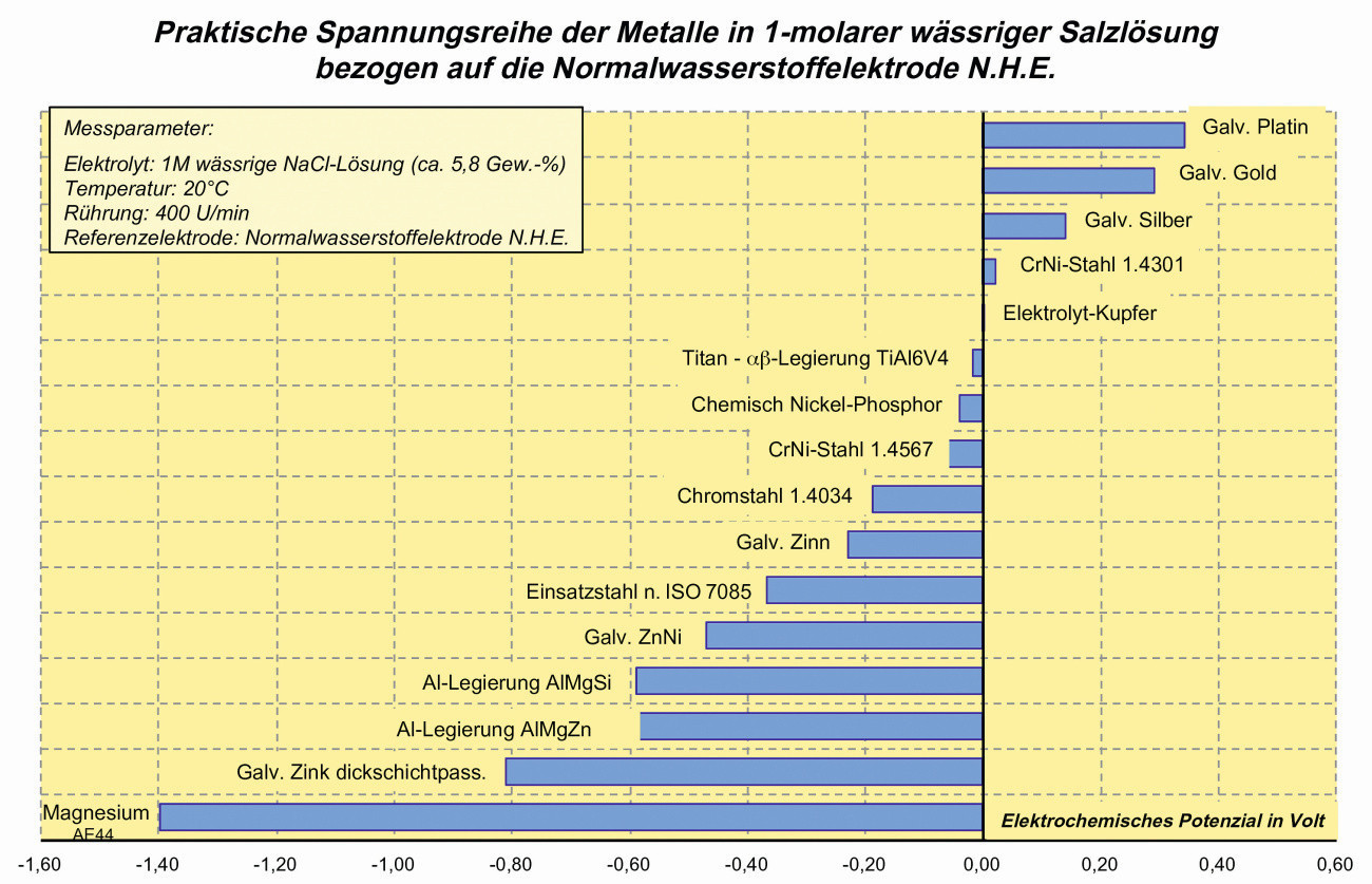 Fig. 9: Free corrosion potential of common materials and protective coatings (vs. NHE)
However, all austenitic steels and non-ferrous metals that have a noble electrochemical potential adapted to CFRP pose problems, see Figure 9. As a rule, however, these "noble metals" are only used for special connecting elements and are not in contact with aluminum. For exterior applications, CrNi steel trim strips are certainly under discussion, especially since the thin anodized aluminum trim strips are also subject to discoloration in certain regions with a high degree of soiling and the unavoidable use of alkaline cleaners. For such an application, the gap dimensions, seals, water drainage and paint system would have to be designed accordingly.
However, the future mixed construction of higher-strength and ultra-high-strength steels in combination with aluminium alloys will presumably characterize the use of materials in automobiles.
Process technology in mixed construction
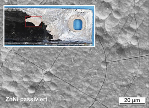 Fig. 10: Missing phosphate layer with paint delamination on a test part with a passivated zinc-nickel surface OEMs use an immersion pre-treatment process to paint the body shell. In the past, zinc phosphating was used, later followed by trication phosphating. As the proportion of aluminum in the baths increases, it is necessary to use sodium hydrogen fluoride in addition. On the one hand, the fluoride causes an increased pickling attack on the aluminum; on the other hand, the aluminum cation Al3+, which hinders layer formation even at low bath concentrations, is complexed into AlF63-. With the addition of sodium hydrogen fluoride, cryolite Na3AlF6 is formed, which is precipitated in the electrolyte. This increasing sludge formation is a certain problem.
For this reason, processes have been developed and established by the major chemical companies Henkel and Metallchemie that enable zinc phosphating on galvanized steel, but no conversion coating takes place on aluminium (only the post-passivation leads to a very thin layer formation). This two-stage concept, which is used by almost all OEMs, has many advantages, but other challenges remain.
The pre-treatment just allows phosphating on Usibor, but if body attachments with a passivation are installed on the body shell, no phosphate layer can form, as the starting reaction (oxidation of zinc or zinc-nickel) is prevented due to the insulation effect (see Fig. 10). In this respect, passivation on body attachments must always be regarded as critical; non-passivated - or at best thinly passivated - surfaces must be used. All body shell screws and hinges must be designed in such a way that the cathodic dip coating adheres firmly to the substrate. As the add-on parts are almost always purchased parts, there is an important interface for joint coordination between the OEM, supplier and coater. The tightening torques for the body shell screws must also be adapted to the higher thread friction coefficients.
Another construction site is the use of magnesium on the body shell. If magnesium is to be used on the body shell, this component must be pretreated and painted separately. The current two-stage phosphating process with subsequent cathodic dip coating is not suitable for magnesium alloys. At best, an in-house, separate pre-treatment for magnesium could be considered in order to place the component in the body shell before the cathodic dip coating. As a rule, however, magnesium components are assembly parts; this was already the case with the tailgate interior part of the VW Lupo and the magnesium dome strut is also used as an assembly part on the Audi A8 (model D5) (see Fig. 11).
Although magnesium is rarely used in car body construction, some applications in the interior, such as the dashboard cross member or the rear seat wall, are certainly conceivable. In this respect, a standardized pre-treatment for zinc, aluminium and magnesium, which realizes a layer-forming conversion coating on all substrates, is highly desirable.
Summary of the process
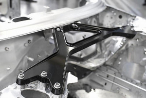 Fig. 11: Magnesium dome strut as an assembly part with KTL and powder coating on the Audi A8Intoday's mixed body construction, aluminum cast nodes are MIG-welded with aluminum extrusion profiles, while aluminum sheets are mechanically joined with conventional, higher-strength or press-hardened steels using punch riveting, friction welding and flanging, including structural bonding.
For joining thick-walled aluminum castings with steel, screw connections (FDS, Flow Drill Screws) with adhesive are generally the method of choice.
Zinc-nickel is generally used to coat the self-pierce rivets and friction elements in order to ensure electrochemical compatibility with aluminum. High process reliability during joining and a high coating quality of the fasteners are essential to prevent crevice and contact corrosion.
In the future, aluminum and steel alloys will characterize mixed construction, with tailor-made heat treatment technologies being used for steel components. The possibility of influencing the cooling rate from the austenite phase as desired and, if necessary, combining it with TMB can significantly reduce material consumption. Magnesium alloys and CFRP will remain in a niche existence, as weight advantages have to be bought with very high corrosion protection costs and CFRP is also very energy-intensive to manufacture. The use of these materials will therefore be limited to largely non-corrosive installation positions.
Uniform pre-treatment for the entire material mix of the body-in-white has so far been ensured by phosphating processes, whereby high aluminum content is critical: Either precipitation deposits in the bath are tolerated or the phosphate layer on aluminum is deliberately avoided for subsequent cathodic dip painting. The development of new conversion coatings, independent of the metal substrate, is therefore a requirement for R & D.


