Coating of aluminum automotive electronics with tin alloys The electroplating of aluminum substrates with end surfaces for contact applications, such as tin and tin alloys, is state of the art, but relatively time-consuming due to the many pre-treatment and process steps involved. Implementation in continuous processes such as coil coating would significantly increase the application possibilities of aluminum-based materials, but at the same time would require a significant reduction in process times. The fem carried out investigations with aluminum substrates as materials for conductors and connectors in automotive electronics.
The aim of the investigations presented was to further develop the entire process chain for electroplated tin alloy deposition on aluminum substrates in such a way that high-quality coatings can be deposited on pure aluminum substrates and on aluminum alloys with higher strengths within reasonable process times.
Introduction
Both copper and aluminum materials are known for their good electrical properties and have therefore been used for decades as base materials for electrical applications. Copper materials are superior to aluminum-based materials, especially when higher thermal or mechanical loads are present [1]. A rough comparison of properties is shown in Table 1 and aluminum materials offer clear advantages in terms of price and weight. If one compares the daily prices for aluminum and copper, the current price per ton is around 2,400 euros for Al and 8,500 euros for Cu [1].
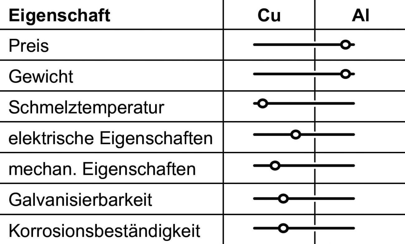 Tab. 1: Comparison of copper and aluminum properties
![Abb. 1: Vergleich Aluminium/Kupfer [2–4] (alle Abb., Tab., Fotos: fem) Abb. 1: Vergleich Aluminium/Kupfer [2–4] (alle Abb., Tab., Fotos: fem)](/images/stories/Abo-2023-03/thumbnails/thumb_gt-2023-03-019.jpg) Fig. 1: Comparison of aluminum/copper [2-4] (all figures, tables, photos: fem)For conductors of the same cross-section made of pure aluminum and pure copper, the following ratios result: the density of aluminum is only about 30 % of that of copper (2.7 to 8.9 g/cm3), the price of the aluminum version is only about 9 % of that of copper and the conductance of aluminum is 63 % of the copper conductance (35 to 58 MS/m).
Fig. 1: Comparison of aluminum/copper [2-4] (all figures, tables, photos: fem)For conductors of the same cross-section made of pure aluminum and pure copper, the following ratios result: the density of aluminum is only about 30 % of that of copper (2.7 to 8.9 g/cm3), the price of the aluminum version is only about 9 % of that of copper and the conductance of aluminum is 63 % of the copper conductance (35 to 58 MS/m).
A slightly different picture emerges when comparing pure aluminum and pure copper with the same conductance, which requires 1.6 times the cross-section of copper when using aluminum. In this case, the weight saving when using aluminum instead of copper is still 50 %, and the price for the aluminum version is only 15 % compared to copper [2-4] (Fig. 1).
Due to the weight and cost advantage of aluminum alloys over copper alloys, the former can be an attractive alternative for certain applications. As a rule, the conditions of use require surface treatment in the form of an electroplated coating [5]. The pre-treatment process, e.g. double zincate process, is particularly complex and time-consuming. With regard to continuous coating, there is a need to further develop the process chain in such a way that high-quality and adhesive coatings can be deposited with reasonable process times.
Experimental materials and processes: Aluminum substrates
The alloys in Table 2 were examined. There were limitations with regard to the availability of other aluminum grades, especially on a sample size scale.
|
Alloy |
Type and dimension |
|
|
Al99.5 |
EN-AW 1050 A |
Strip material, 0.5 mm sheet rolled, 40 x 40 x 2 mm |
|
AlMg3 |
EN-AW 5754 |
Strip material, rolled sheet, 40 x 40 x 2 mm |
|
AlZn5.5MgCu |
EN-AW 7075 |
Round material, Ø 30 mm, L = 30 mm Rolled sheet metal, 40 x 40 x 2 mm |
|
AlMg4.5Mn0.7 |
EN-AW 5083 |
Round material, Ø 30 mm, L = 30 mm |
Pre-treatment
The zincate pre-treatment usually used for aluminum coating is a multi-stage process and comprises the following process steps ("double zincate"):
- Degreasing
- pickling
- Clarifying
- Zincate treatment
- Brightening (removal of the first zincate layer)
- Zincate treatment
At least one-stage rinsing processes are required as intermediate steps. Possible process variants result from the different requirements of the aluminum alloy used and its surface condition.
The following commercial pre-treatment systems were used for the tests:
- Chemofit FLD AL (Chemopur H. Brand GmbH)
- Diaprep (IPT International Plating GmbH)
In both pretreatment systems, boil-off degreasing was replaced by cleaning with ethanol, as the former cannot achieve a degreasing effect within the desired process time. The treatment time of each treatment step was varied between 10-30s.
Electrolytes
Tin or tin alloy systems were selected as the final surfaces for the various aluminum substrates. A selection of suitable electrolytes is shown in Table 3.
|
System |
Layer composition |
Parameters |
Advantages |
Disadvantages |
|
Sn-Ag |
3.5 % Ag |
strongly acidic, RT, 10-20 A/dm2 |
suitable for strip processing (several µm/min) |
Intermediate layer on Al required |
|
Sn-Cu |
1-10 % Cu |
strongly acidic, 50 °C 10-80 A/dm2 |
||
|
Sn-Bi |
5 % Bi |
strongly acidic, 40 °C 1-20 A/dm2 |
||
|
Sn-Zn |
30 % Zn |
pH 6-7, RT, |
Al directly coatable, very corrosion-resistant layers |
Rack electrolytes (max. 0.5-1 µm/min) |
|
Sn-Zn-Co |
51 % Zn, 3 % Co |
pH 6-10, 20-70 °C, 1-5 A/dm2 |
The selection of different tin and tin alloy electrolytes presented in the table can be divided into two groups. On the one hand, there are various electrolytes suitable for strip processing equipment available on the market that can be used to achieve very high deposition rates. However, as these electrolytes have strongly acidic pH values, it is necessary to provide the zincate-treated aluminum substrate with an intermediate layer (usually nickel). The second group consists of rack electrolytes, which require somewhat longer deposition times and operate in the neutral to slightly alkaline range. As a result, it may not be necessary to apply an intermediate layer, which would eliminate the disadvantages in terms of deposition speed compared to the conveyor belt electrolytes. One representative from each group was examined:
- Tin-silver electrolyte Slotoloy SNA 30 (Schlötter): As a representative of the first electrolyte group (strongly acidic, band electrolyte), the electrolyte SNA30 from Schlötter based on methanesulfonic acid was selected. This deposits tin-silver layers with an Ag content of around 3% by weight.
- Tin-zinc electrolyte Dipsol SZ 240 (Dipsol Europe GmbH): The tin-zinc electrolyte SZ 240 from Dipsol was selected as a representative of the second electrolyte group (neutral, rack electrolyte). Layers with a composition of approx. 70 % tin and 30 % zinc can be deposited from this electrolyte.
- Nickel sulphamate electrolyte MS (Schlötter): The additive-free nickel sulphamate electrolyte MS from Schlötter was used for the nickel intermediate layer in both electrolyte systems. The coatings were applied at a current density of 15 A/dm2 at a temperature of 55 °C.
Coating process
The sketch in Figure 2 schematically shows the coating process with or without an intermediate layer using the example of the tin-silver or tin-zinc electrolyte.
 Fig. 2: Process variants for the different electrolyte types (schematic)
Coating systems used
A test setup with several bath tanks (volume 5 liters) for the individual pretreatment and coating stages was used to coat the films (see Fig. 3 and 4). The samples were moved in the electrolyte with the aid of an agitator, comparable to a rotating electrode, to simulate the conditions in the conveyor belt system. Samples in foil form were clamped in a holder as belt sections of 200 mm length, extruded cylindrical samples of 30 mm diameter were fixed directly in the agitator. The different "belt speeds" were achieved by setting the corresponding speed of the agitator. The coating of flat substrates was also carried out on a 5 liter scale with fabric movement.
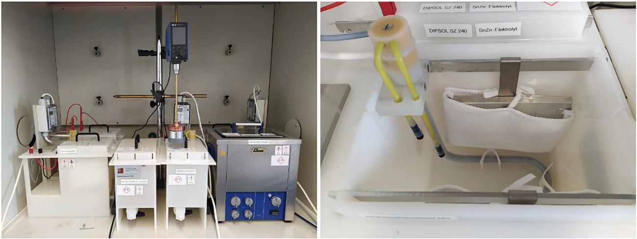 Fig. 3: Arrangement of bath tank in the fume cupboard (left), interior view of bath tank (right)
Results
The samples were characterized with regard to adhesive strength, contact resistance and corrosion resistance. Both the POSI (pull-off adhesion) test and the temperature shock test were used to assess the adhesive strength. The POSI test offers the advantage over the temperature shock test that quantitative values for the adhesion strength can be determined, but requires flat samples. The temperature shock test was used for films or round material.
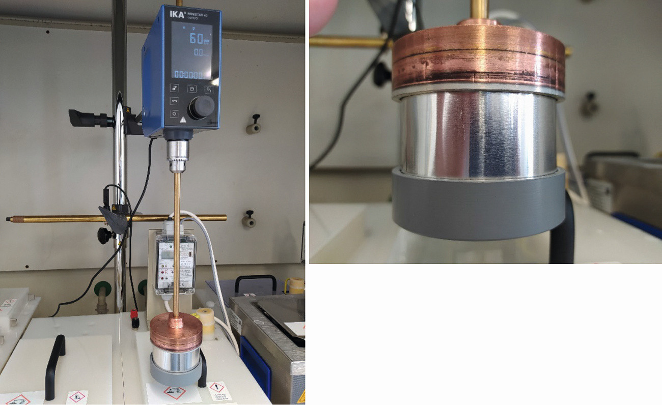 Fig. 4: Rotation device for coating tape sections (left), sample holder with clamped film (right)
Adhesion tests Temperature shock test
The temperature shock test was used to qualitatively assess the adhesive strength of the various combinations of substrate, pre-treatment and coating, particularly for non-planar substrates (films or round material). The coated samples were aged for 2 hours at 200 °C and then quenched in cold water. Due to the different coefficients of thermal expansion of the substrates and the applied coatings, it is possible that these may partially lift off the substrate if the adhesive strength is too low, resulting in the formation of bubbles.
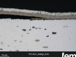
In the case of the AlMg3 substrates, bubble formation was registered in isolated cases after the temperature shock test. Their occurrence is independent of the pre-treatment series, the electrolyte system used and the presence of a nickel intermediate layer (Fig. 5).
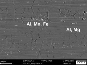
The scanning electron microscopic examination of an uncoated AlMg3 sample shows fissured surface areas as well as areas containing manganese and iron (Fig. 6). In such areas, activation difficulties during pre-treatment could result in adhesion problems.
On a coated AlMg3 sample, EDX was used to prove that zinc (from the zincate pretreatment) is not only present on the aluminum surface, but has partially penetrated into deeper areas of the substrate (Fig. 7). This may be due to the presence of cracks in the surface, for example, so that zincate pickling penetrates into the grain boundaries in areas close to the surface and is deposited there. This causes the grain boundaries to disintegrate and individual areas to break off. As a result of the stress during the thermal shock test, the nickel interlayer separates from the substrate and breaks.
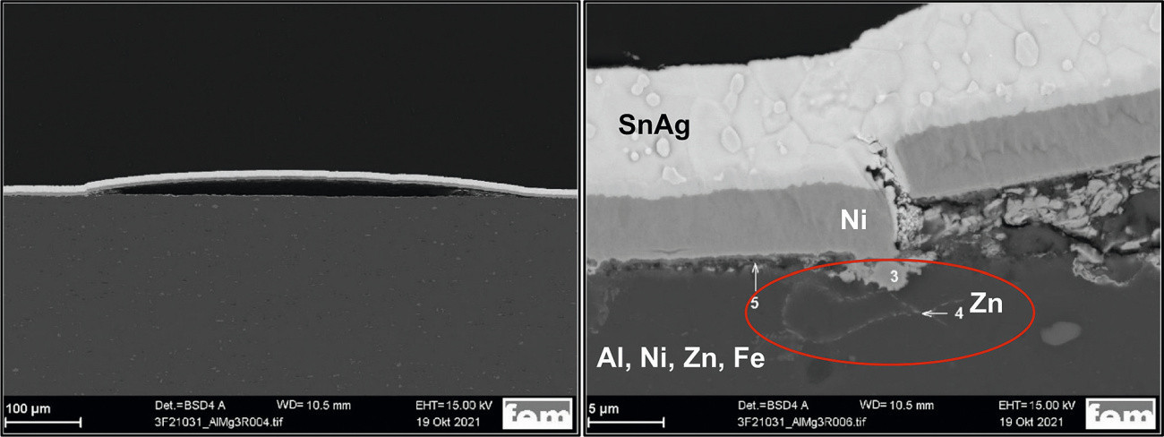 Fig. 7: SEM cross-section of a sample after the thermal shock test (AlMg3, Chemopur pre-treatment, intermediate layer Ni, final layer SnAg, left: Overview, right: Detail
In the case of the AlZn5.5MgCu samples, adhesion problems occasionally occur in the coating without an intermediate nickel layer, irrespective of the pre-treatment series and the final layer. The detachments are not extensive, but locally limited in the form of small bubbles (Fig. 8).
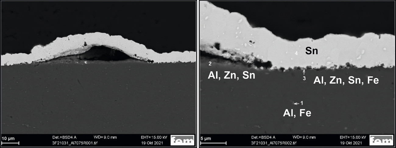 Fig. 8: SEM cross-section of an AlZn5.5MgCu sample, pre-treatment IPT, coating SnAg, left: Overview, right: detail
On the surface of an uncoated AlZn5.5MgCu sample, there are still relatively large areas with deposits of aluminum and magnesium oxides or copper, which may only be incompletely removed by activation, making the adhesive strength of a subsequent coating more difficult (Fig. 9).
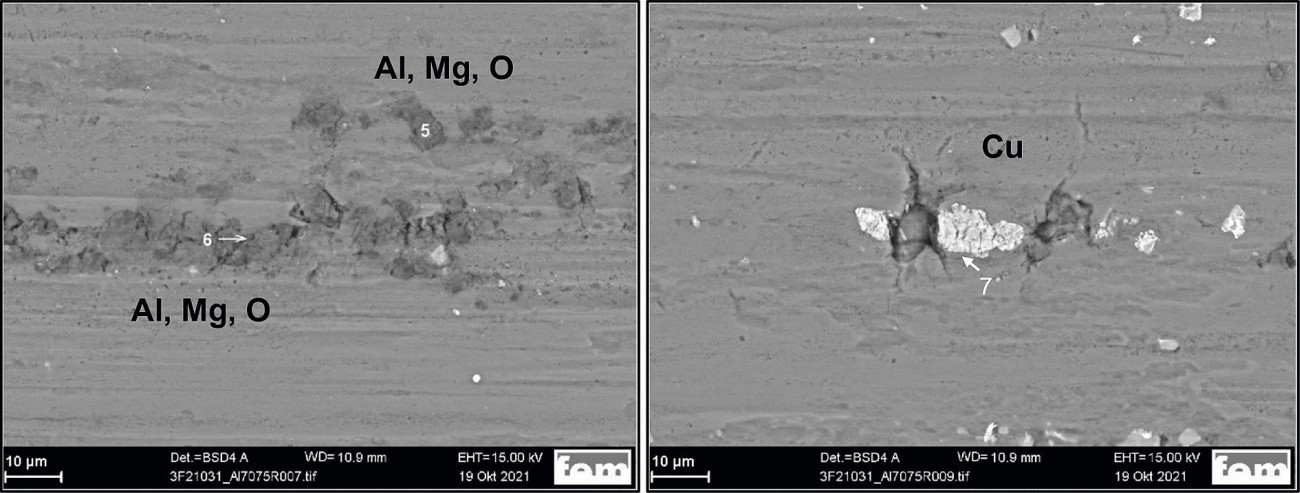 Fig. 9: SEM surface image of an uncoated AlZn5.5MgCu sample
POSI test
![Abb. 10: Verwendetes Haftfestigkeitsprüfgerät DeFelsko PosiTest AT-A [9] Abb. 10: Verwendetes Haftfestigkeitsprüfgerät DeFelsko PosiTest AT-A [9]](/images/stories/Abo-2023-03/thumbnails/thumb_gt-2023-03-015.jpg) Fig. 10: DeFelsko PosiTest AT-A adhesion tester used [9]The POSI test (Fig. 10) offers the advantage over the temperature shock test that quantitative values for the adhesive strength can be determined, but requires flat samples. It is an adhesive tensile strength test according to ISO 4624 / 16276-1, ASTM D4541 / D7234, AS/NZS 1580 and ZTV-ING (class 1 according to DIN 51220).
Fig. 10: DeFelsko PosiTest AT-A adhesion tester used [9]The POSI test (Fig. 10) offers the advantage over the temperature shock test that quantitative values for the adhesive strength can be determined, but requires flat samples. It is an adhesive tensile strength test according to ISO 4624 / 16276-1, ASTM D4541 / D7234, AS/NZS 1580 and ZTV-ING (class 1 according to DIN 51220).
The POSI test is used to measure the force required to peel a defined area of a coating from a substrate using hydraulic pressure. The required pressure is specified in megapascals (MPa) and pounds per square inch (PSI) on a digital precision dial gauge. A test stamp ("dolly") with a diameter of 14 mm was used for the tests. The measuring range is between 0 and 40 MPa. The dolly is glued to the cleaned substrate surface and the adhesive is then cured. The test surface to be measured is exposed with a circular hole saw and the measurement is carried out. After several preliminary test series for quantitative adhesive strength testing, it became clear that the adhesive strength values are subject to strong fluctuations with a pre-treatment time of less than 30 s per process step, regardless of the pre-treatment series and aluminum alloy. An adhesive coating cannot therefore be guaranteed. Only samples with a pretreatment duration of 30 s per process step were considered for the further tests. A summary of the test results is shown in Figure 11.
The following criteria were used to evaluate the adhesive strength: good adhesive strength ≥ 4 MPa (green), medium adhesive strength 3.7-3.9 MPa (yellow), low adhesive strength ≤ 3.6 MPa (red). Usually the tear occurs between the substrate and the coating and the specified value corresponds to the actual adhesive strength. If the numerical value is preceded by an equals sign (≥), the tear-off between the stamp and coating has occurred and the actual adhesive strength between the substrate and coating is greater.
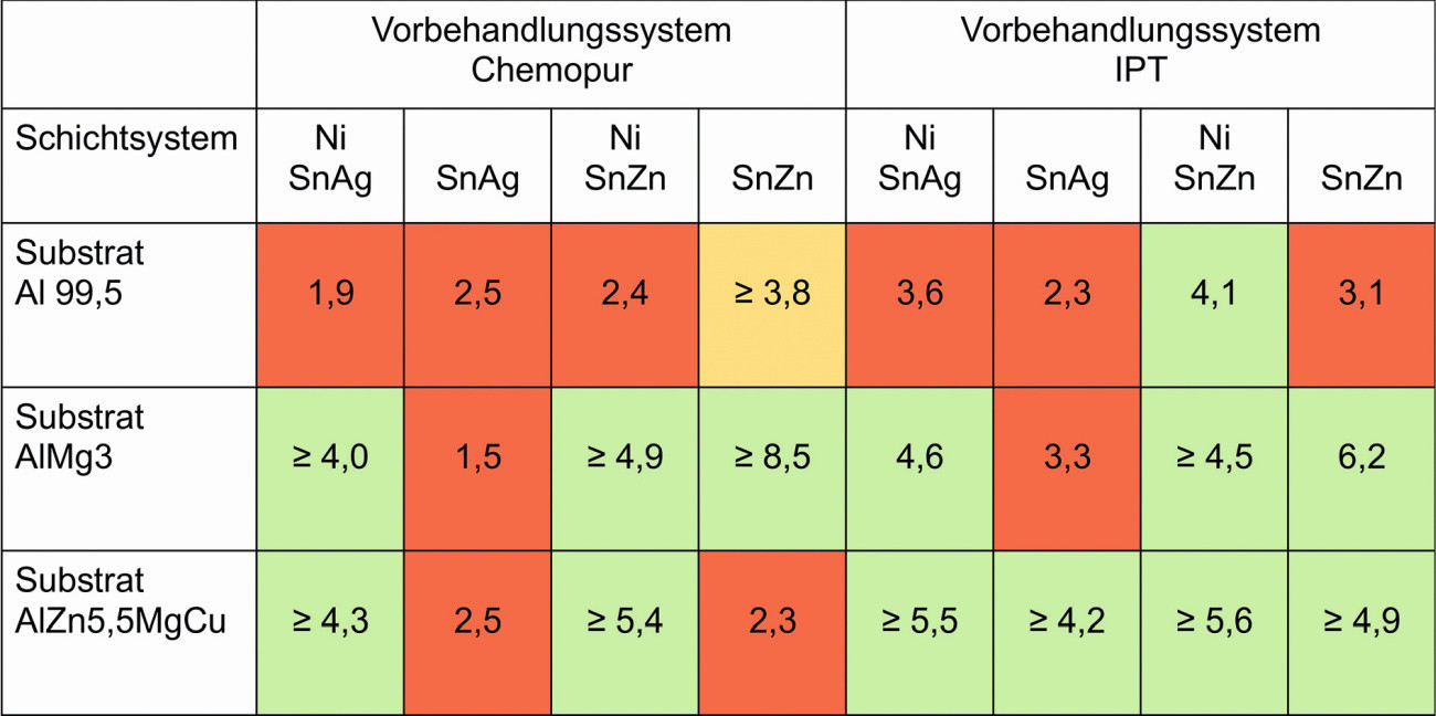 Fig. 11: Adhesive strength values after the POSI test, all values in MPa
If the substrates are compared with each other, the adhesion values for the pure aluminum substrates Al99.5 are rather low, regardless of the pre-treatment and the coating system. Only the tin-zinc coating system with a nickel intermediate layer and IPT pre-treatment achieves a sufficient value. For the aluminum alloy AlMg3, good adhesion values are achieved when coating with tin-silver with a nickel intermediate layer. When coating with tin-zinc, good adhesion values are achieved with and without a nickel intermediate layer. This is the case for both pre-treatment series.
Good adhesion values are achieved for the aluminum alloy AlZn5.5MgCu when coated with tin-silver and tin-zinc using the Chemopur pretreatment series and in the presence of a nickel intermediate layer. With the IPT pre-treatment series, good adhesion values are achieved for all combinations on this substrate.
If the pre-treatments are compared with each other, Chemopur and IPT on Al99.5 show only a low adhesion strength. The adhesion strength on the Al alloys AlMg3 and AlZn5.5MgCu is good for both pretreatment lines and the coating systems with nickel interlayer (Chemopur pretreatment) or all coating systems (IPT pretreatment).
From the point of view of the coating systems, both coating systems achieve only a low adhesion strength on the pure aluminum substrate. The adhesion strength of the tin-silver coating without a nickel intermediate layer is also low. The adhesion strength on the Al alloys AlMg3 and AlZn5.5MgCu is good for both pre-treatment lines and the coating systems with a Ni intermediate layer (Chemopur pre-treatment) or all coating systems (IPT pre-treatment).
Contact resistance measurements
The contact resistance measurements were carried out on coated flat samples against a gold-coated pin with a semi-circular contact surface and a diameter of 0.8 mm. The force was applied manually in a force measuring stand, measured using a load cell and evaluated using a measuring amplifier. The current was applied and the voltage drop measured at the pin using soldered measuring leads. The flat samples were contacted via a gold-plated Kelvin terminal. To determine each resistance value, ten different currents of 0.1-1 A were impressed and the respective voltage drop measured. The contact pressure was varied from 0.1 N to 2.0 N and the contact resistance was determined as a function of this. The results obtained from the contact resistance measurements are plotted as resistance vs. contact force in Figure 12.
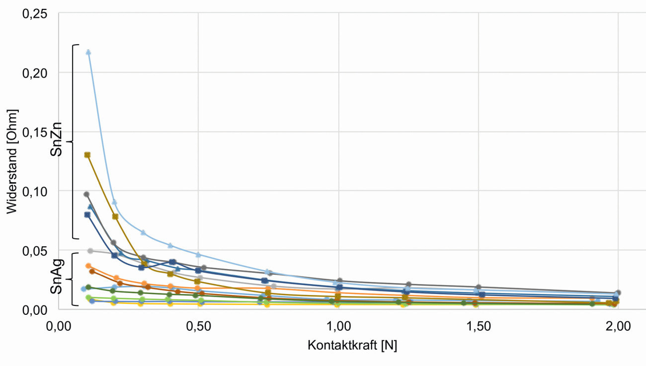 Fig. 12: Contact resistance as a function of contact force
The tin-silver and tin-zinc coatings exhibit the same contact resistance at higher contact forces (< 0.25 Ohm from 0.75 N contact force). The contact resistance is not influenced by any nickel intermediate layer that may have been applied. The tin-zinc coating has higher resistance values at a lower contact force than 0.75 N than the tin-silver coating, as the layers are rougher and are only leveled by the measuring pin at a higher contact force (the contact surface is adapted to the measuring pin).
Corrosion tests
The corrosion tests were carried out on coated samples. They were aged for 48 h in the neutral salt spray test NSS. In many cases, clear signs of corrosion can be seen on the surfaces in Figure 13. For reasons of clarity, the samples with low corrosion attack are highlighted in green. The following samples tend to be less affected: the tin-zinc coating without a nickel intermediate layer, regardless of the pre-treatment series, and the tin-silver coating with the Chemofit pre-treatment series from Chemopur with or without a nickel intermediate layer, depending on the substrate used.
Summary
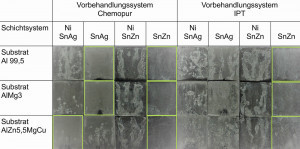 Fig. 13: Photo documentation of the samples after 48 h aging in the NSS, green markings for samples with low corrosion attackTheimplementation of aluminum substrates in continuous processes such as coil coating requires a significant reduction in process times. The main objective of the presented investigations was the production of adhesive tin alloy coatings on various aluminum substrates with process times that are acceptable in coil coating lines. The tests were carried out using commercial zincate processes and tin alloy electrolytes on various aluminum alloys. The corrosion resistance of the coatings was assessed after 48 hours of ageing in a neutral salt spray test, with signs of corrosion being observed in many cases. The best results were achieved for the tin-zinc coatings without an intermediate layer and for tin-silver coatings with the Chemopur pre-treatment. The contact resistances of the tin-silver and tin-zinc alloy coatings were similar at higher contact forces (< 0.25 Ω from 0.75 N contact force). At lower contact forces, the tin-zinc coatings showed slightly higher values compared to tin-silver, due to their slightly higher roughness. With regard to the adhesive strength, good quality coatings were produced with process times of 30 s for higher alloyed aluminum qualities. The surface quality of the aluminum alloys proved to be of particular importance here. It has been shown that cracks in the surface or precipitation of alloy components can lead to the formation of blisters or layer detachment.
The IGF project AiF 22009 N of the research associations DGO and fem was funded via the AiF within the framework of the program for the promotion of joint industrial research (IGF) by the Federal Ministry of Economics and Climate Protection on the basis of a resolution of the German Bundestag.
Literature
[1] Lücke, N.; Schlegel, S.; Großmann, S.: Comparison of materials based on Cu and Al and trends in their application in electrical power engineering, Metall, 67. Jahrgang, 11 (2013), 493-497
[2] Daily rates copper, aluminum: https://www.finanzen.net/rohstoffe/kupferpreis, https://www.finanzen.net/rohstoffe/aluminiumpreis, retrieved on 27.01.2023
[3] The material aluminum, information sheet W1, AluminiumZentrale, Gesamtverband der Aluminium-Industrie(http://www.aluinfo.de/files/_media/dokumente/Downloads/Technische%20Daten/Merkblaetter/W1_Der_Werkstoff_Aluminium.pdf)
[4] Copper data sheets, Copper Institute https://kupfer.de/mediathek/datenblaetter/
[5] Jelinek, T.W.: Surface treatment of aluminum, Leuze Verlag, Bad Saulgau, 1997
[6] GDA Gesamtverband der Aluminiumindustrie e. V., Merkblatt O8: Galvanische und chemische Überzüge, www.aluinfo.de
[7] Arbeitsanleitungen der Elektrolyte MBF20, Slotoloy SNA30, Slotoloy SNB30 1, Slototin 60(www.schloetter.de)
[8] Elektrolytbeschreibung Fa. Dipsol, auf Anfrage erhältlich
[9] POSI-Test von DeFelsko https://de.defelsko.com/positest-at?gclid=EAIaIQobChMIstKq85n6-AIVB_hRCh2UEQsJEAAYAiAAEgJiSPD_BwE


